Page 1228 of 2267
Lighting condition of the bulb System condition Reference item
NEL531 IGN ON
ON
OFF1 sec.
No malfunction is detected.
No further action is neces-
sary.
—
NEL532 IGN ON
ON
OFF1 sec.2 sec. 2 sec.
0.5 sec.
Front sensor or front sensor
circuit is malfunctioning.
(When rear sensor OK)Go to DIAGNOSTIC
PROCEDURE 1
(EL-97).
NEL533 IGN ON
ON
OFF1 sec.2 sec. 2 sec.
0.5 sec. 0.5 sec.
Rear sensor or rear sensor
circuit is malfunctioning.
(Whatever the state of front
sensor)Go to DIAGNOSTIC
PROCEDURE 2
(EL-97).
NEL534 IGN ON
ON
OFF1 sec.2 sec. 2 sec.
0.5 sec. 0.5 sec.
Sensor supply is malfunction-
ing.Go to DIAGNOSTIC
PROCEDURE 1 and
2 (EL-97).
NEL535 IGN ON
ON
OFF1 sec.2 sec. 2 sec.
0.5 sec. 0.5 sec.
Aiming motor or aiming motor
circuit is malfunctioning.Go to DIAGNOSTIC
PROCEDURE 3
(EL-98).
NEL536 IGN ON
ON
OFF
Auto level control unit is mal-
functioning.Replace auto level
control unit.
HEADLAMP—Headlamp Aiming Control (Auto)—
Trouble Diagnosis (Cont’d)
EL-96
Page 1229 of 2267
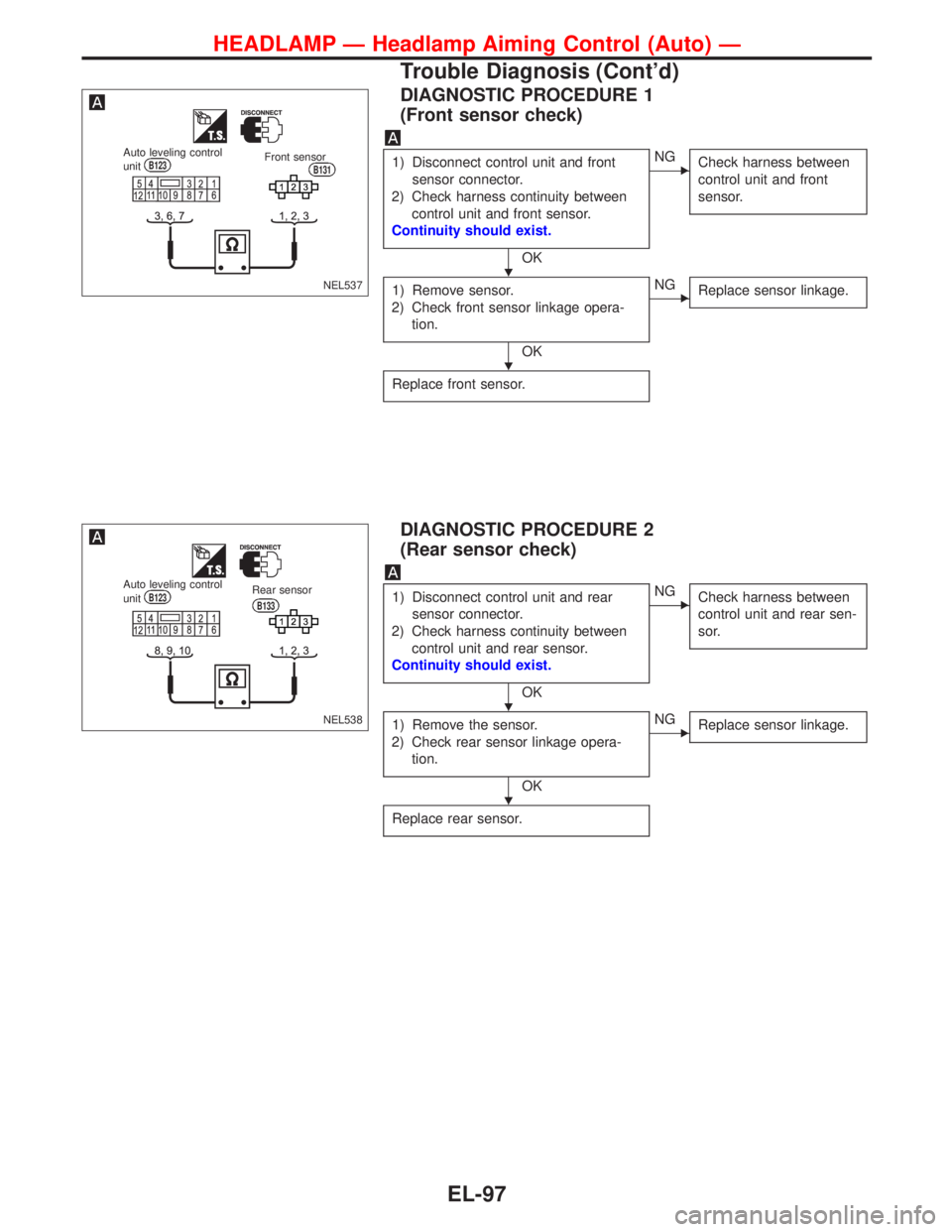
DIAGNOSTIC PROCEDURE 1
(Front sensor check)
1) Disconnect control unit and front
sensor connector.
2) Check harness continuity between
control unit and front sensor.
Continuity should exist.
OK
�NG
Check harness between
control unit and front
sensor.
1) Remove sensor.
2) Check front sensor linkage opera-
tion.
OK
�NG
Replace sensor linkage.
Replace front sensor.
DIAGNOSTIC PROCEDURE 2
(Rear sensor check)
1) Disconnect control unit and rear
sensor connector.
2) Check harness continuity between
control unit and rear sensor.
Continuity should exist.
OK
�NG
Check harness between
control unit and rear sen-
sor.
1) Remove the sensor.
2) Check rear sensor linkage opera-
tion.
OK
�NG
Replace sensor linkage.
Replace rear sensor.
NEL537
Auto leveling control
unitB123Front sensorB131
NEL538
Auto leveling control
unitB123Rear sensor
B133
�
�
�
�
HEADLAMP—Headlamp Aiming Control (Auto)—
Trouble Diagnosis (Cont’d)
EL-97
Page 1230 of 2267
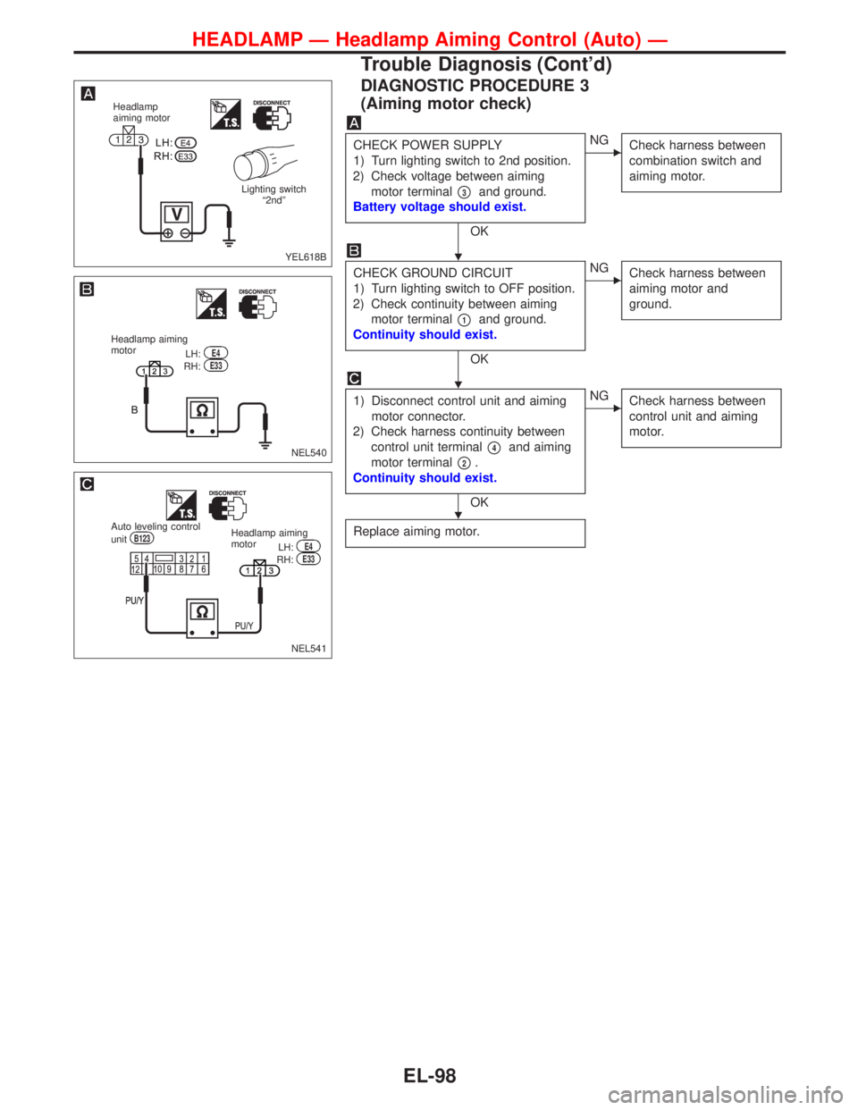
DIAGNOSTIC PROCEDURE 3
(Aiming motor check)
CHECK POWER SUPPLY
1) Turn lighting switch to 2nd position.
2) Check voltage between aiming
motor terminal
�3and ground.
Battery voltage should exist.
OK
�NG
Check harness between
combination switch and
aiming motor.
CHECK GROUND CIRCUIT
1) Turn lighting switch to OFF position.
2) Check continuity between aiming
motor terminal
�1and ground.
Continuity should exist.
OK
�NG
Check harness between
aiming motor and
ground.
1) Disconnect control unit and aiming
motor connector.
2) Check harness continuity between
control unit terminal
�4and aiming
motor terminal
�2.
Continuity should exist.
OK
�NG
Check harness between
control unit and aiming
motor.
Replace aiming motor.
YEL618B
Headlamp
aiming motor
Lighting switch
“2nd”
NEL540
Headlamp aiming
motor
LH:E4RH:E33
NEL541
Auto leveling control
unitB123Headlamp aiming
motor
LH:E4RH:E33
�
�
�
HEADLAMP—Headlamp Aiming Control (Auto)—
Trouble Diagnosis (Cont’d)
EL-98
Page 1231 of 2267
Removal and Installation
Front sensor
YEL621B
4.0 - 5.0 (0.4 - 0.51, 35 - 44)
Front linkage to be clamped onto
stabilizer bar with wheels down
and suspension settled. Rotation
to be fixed with link arm in hori-
zontal plane.
18 mm (0.71 in)
3.3 - 7.7 (0.33 - 0.79, 29 - 68)
Rear sensor
3.3 - 7.7 (0.33 - 0.79, 29 - 68)
:N·m (kg-m, in-lb)3.3 - 7.7 (0.33 - 0.79, 29 - 68)The rear sensor linkage does not
require setting, but with the wheel on
the ground and the suspension
settled, ensure that the link arm in the
same plane as the connector wire.
HEADLAMP—Headlamp Aiming Control (Auto)—
EL-99
Page 1269 of 2267
Headlamp
Wattage (12 volt)
High/low (without xenon headlamp) 55/55
High/low (with xenon headlamp) 55/Discharge D2S type
Exterior Lamp
Wattage (12 volt)
Front combination lampParking 5
Turn signal 21
Front fog lamp 55 (H1)
Rear combination lampTurn signal 21
Stop/Tail 21/5
Back-up 21
Side turn signal lamp 5
License plate lamp 5
High-mounted stop lamp 21
Interior Lamp
Wattage (12 volt)
Interior lamp 10
Map lamp 3
Step lamp 3.4
Trunk room lamp 3.4
Luggage room lamp 5
BULB SPECIFICATIONS
EL-137
Page 1332 of 2267
Wiring Diagram—HLC—
YEL319B
B
G
12
LG/Bd13GE104
2
E128
3
B R/B
B
A
5 LG/B4 G2 P/L
E126
P/L
P/L
3
OR/B1
R/B
E37E11
L
EL-HLC-01
E126
E104
E38
XH HD
HD 10A 30A
XH
HD
1 2 OR/B
BE38
M
B
B
12
E1281
36
24
5 3
241
5
BATTERYIGNITION SWITCH
ON or START
FUSE
BLOCK
(J/B)Refer to EL-POWER.: With XENON headlamp or day-
time light system
: Except
HEADLAMP
WASHER TIMERNext page
HEADLAMP
WASHER
MOTORHEADLAMP
WASHER
SWITCH
OFFON
REFER TO THE FOLLOWING
FUSE BLOCK - Junction Box (J/B)
HEADLAMP WASHER
EL-200
Page 1333 of 2267
YEL179C
: With gasoline engine
: With diesel engine
: With XENON headlamp or
daytime light system
: Except
: With daytime light system and
without XENON headlamp
: With daytime light system
and XENON headlamp
: With XENON headlamp and
without daytime light system.BATTERY
Refer to EL-POWER.
OFF1ST2ND
OFF1ST2ND
COMBINATION
SWITCH
(LIGHTING SWITCH)
LOW
HIGH
Preceding
page
DIODE HEADLAMP
RELAY RHHEADLAMP
RELAY RHHEADLAMP
RELAY RH
Preceding
page
To Headlamp RH
(Refer to EL-H/LAMP and
EL-DTRL)PASS
HEADLAMP WASHER
Wiring Diagram—HLC—(Cont’d)
EL-201
Page 1334 of 2267
Washer Tube Layout
Check Valve
�A check valve is provided in the washer fluid line. Be careful
not to connect check valve to washer tube in the wrong
direction.
NEL555 To reservoir tankWasher nozzle
Check valve
NEL554 From res-
ervoir
tankCheck valve
To
nozzle
To
nozzle
HEADLAMP WASHER
EL-202


Front linkage to be clamped onto
stabilizer bar with wheels down
and suspension settled. Rotation
to be fixed with link ar")

High/low (without xenon headlamp) 55/55
High/low (with xenon headlamp) 55/Discharge D2S type
Exterior Lamp
Wattage (12 volt)
Front combination lampParking 5
Turn signal 21
F")


