Page 1220 of 2267
YEL142C
Preceding
page
HEADLAMP AIM-
ING SWITCH
Preceding
page
HEADLAMP
AIMING
MOTOR LHHEADLAMP
AIMING
MOTOR RH
HEADLAMP—Headlamp Aiming Control (Manual)—
Wiring Diagram—H/AIM—(Cont’d)
EL-88
Page 1221 of 2267
MODELS AFTER VIN - P11U0548750
YEL834C
HEADLAMP—Headlamp Aiming Control (Manual)—
Wiring Diagram—H/AIM—(Cont’d)
EL-89
Page 1222 of 2267
YEL835C
HEADLAMP—Headlamp Aiming Control (Manual)—
Wiring Diagram—H/AIM—(Cont’d)
EL-90
Page 1223 of 2267

System Description
The auto level control unit is designed to adjust the beam angle of the headlamp in response to the load-
ing conditions of the vehicle. It is not designed to compensate for the dynamic handling of the vehicle.
The vehicle’s front and rear height is measured by sensors attached to the front stabilizer bar and the rear
suspension lateral link arm. The sensors provide a signal to the auto level control unit, which calculates the
correct headlamp aiming position and sends a signal to the aiming motors.
Initialisation
After the replacement or adjustment of any suspension sensor, the system must be self calibrated. This is
achieved as follows.
The vehicle must be empty, since any load will result in an invalid calibration. From outside of the vehicle
turn ignition on and then within 7 seconds the light switch must be turned from off to side lights on position,
5 times, finishing with the lamps in the on position.
The headlamps will then move to the highest, then the lowest then the normal position to indicate that the
calibration is successful, as can be seen by the moving beam pattern.
After successful calibration the headlamps must then be aimed in the conventional manner. Refer to EL-70.
HEADLAMP—Headlamp Aiming Control (Auto)—
EL-91
Page 1224 of 2267
Component Parts and Harness
Connector Location
NEL528
Auto level control unit
Rear sensor
Headlamp aiming motor RH
Front sensor
Headlamp aiming motor LH
Rear sensor
Auto level control unit Front sensor Headlamp
aiming motor
HEADLAMP—Headlamp Aiming Control (Auto)—
EL-92
Page 1225 of 2267
Wiring Diagram—H/AIM—
AUTO
YEL836C
HEADLAMP—Headlamp Aiming Control (Auto)—
EL-93
Page 1226 of 2267
YEL837C
HEADLAMP—Headlamp Aiming Control (Auto)—
Wiring Diagram—H/AIM—(Cont’d)
EL-94
Page 1227 of 2267
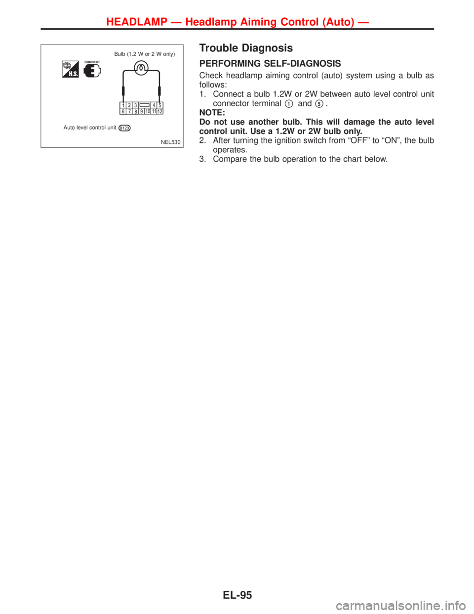
Trouble Diagnosis
PERFORMING SELF-DIAGNOSIS
Check headlamp aiming control (auto) system using a bulb as
follows:
1. Connect a bulb 1.2W or 2W between auto level control unit
connector terminal
�1and�5.
NOTE:
Do not use another bulb. This will damage the auto level
control unit. Use a 1.2W or 2W bulb only.
2. After turning the ignition switch from“OFF”to“ON”, the bulb
operates.
3. Compare the bulb operation to the chart below.
NEL530
Auto level control unitBulb (1.2 W or 2 W only)
HEADLAMP—Headlamp Aiming Control (Auto)—
EL-95
—
Wiring Diagram—H/AIM—(Cont’d)
EL-88")
—
Wiring Diagram—H/AIM—(Cont’d)
EL-89")
—
Wiring Diagram—H/AIM—(Cont’d)
EL-90")

—
EL-93")
—
Wiring Diagram—H/AIM—(Cont’d)
EL-94")