1999 NISSAN PRIMERA Control
[x] Cancel search: ControlPage 1815 of 2267
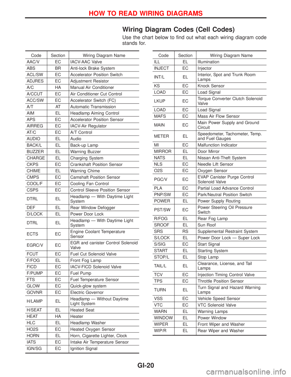
Wiring Diagram Codes (Cell Codes)
Use the chart below to find out what each wiring diagram code
stands for.
Code Section Wiring Diagram Name
AAC/V EC IACV-AAC Valve
ABS BR Anti-lock Brake System
ACL/SW EC Accelerator Position Switch
ADJRES EC Adjustment Resistor
A/C HA Manual Air Conditioner
A/CCUT EC Air Conditioner Cut Control
ACC/SW EC Accelerator Switch (FC)
A/T AT Automatic Transmission
AIM EL Headlamp Aiming Control
APS EC Accelerator Position Sensor
AIRREG EC IACV-Air Regulator
AT/C EC A/T Control
AUDIO EL Audio
BACK/L EL Back-up Lamp
BUZZER EL Warning Buzzer
CHARGE EL Charging System
CKPS EC Crankshaft Position Sensor
CHIME EL Warning Chime
CMPS EC Camshaft Position Sensor
COOL/F EC Cooling Fan Control
CSPS EC Control Sleeve Position Sensor
DTRL ELHeadlamp Ð With Daytime Light
System
DEF EL Rear Window Defogger
D/LOCK EL Power Door Lock
DTRL ELHeadlamp Ð With Daytime Light
System
ECTS ECEngine Coolant Temperature
Sensor
EGRC/V ECEGR and canister Control Solenoid
Valve
FCUT EC Fuel Cut Solenoid Valve
F/FOG EL Front Fog Lamp
FICD EC IACV-FICD Solenoid Valve
F/PUMP EC Fuel Pump
FTS EC Fuel Temperature Sensor
GLOW EC Quick-glow system
GOVNR EC Electric Governor
H/LAMP ELHeadlamp Ð Without Daytime
Light System
H/SEAT EL Heated Seat
HEAT HA Heater
HLC EL Headlamp Washer
HO2S EC Heated Oxygen Sensor
HORN EL Horn, Cigarette Lighter, Clock
IATS EC Intake Air Temperature Sensor
IGN/SG EC Ignition SignalCode Section Wiring Diagram Name
ILL EL Illumination
INJECT EC Injector
INT/L ELInterior, Spot and Trunk Room
Lamps
KS EC Knock Sensor
LOAD EC Load Signal
LKUP ECTorque Converter Clutch Solenoid
Valve
LOAD EC Load Signal
MAFS EC Mass Air Flow Sensor
MAIN ECMain Power Supply and Ground
Circuit
METER ELSpeedometer, Tachometer, Temp.
and Fuel Gauges
MI EC Malfunction Indicator
MIRROR EL Door Mirror
NATS EL Nissan Anti-Theft System
NLS EC Needle Lift Sensor
O2S EC Oxygen Sensor
PGC/V ECEVAP Canister Purge Control
Solenoid Valve
PLA EC Partial Load Advance Control
PNP/SW EC Park/Neutral Position Switch
POWER EL Power Supply Routing
PST/SW ECPower Steering Oil Pressure
Switch
R/FOG EL Rear Fog Lamp
SROOF EL Sun Roof
SRS RS Supplemental Restraint System
S/LOCK EL Power Door Lock Ð Super Lock
S/SIG EC Start Signal
START EL Starting System
STOP/L EL Stop Lamp
TAIL/L ELClearance, License, and Tail
Lamps
TCV EC Injection Timing Control Valve
TPS EC Throttle Position Sensor
TURN ELTurn Signal and Hazard Warning
Lamps
VSS EC Vehicle Speed Sensor
VTC EC VTC Solenoid Valve
WARN EL Warning Lamps
WINDOW EL Power Window
WIPER EL Front Wiper and Washer
WIP/R EL Rear Wiper and Washer
HOW TO READ WIRING DIAGRAMS
GI-20
Page 1826 of 2267
Voltage check method
1. Remove the blown fuse and disconnect all loads (i.e. SW1 open, relay disconnected and solenoid dis-
connected) powered through the fuse.
2. Turn the ignition key to the ON or START position. Verify battery voltage at the B
+side of the fuse ter-
minal (one lead on the B
+terminal side of the fuse block and one lead on a known good ground).
3. With SW1 open and the DMM leads across both fuse terminals, check for voltage.
voltage; short is between fuse block and SW1 (point A).
no voltage; short is further down the circuit than SW1.
4. With SW1 closed, relay and solenoid disconnected and the DMM leads across both fuse terminals, check
for voltage.
voltage; short is between SW1 and the relay (point B).
no voltage; short is further down the circuit than the relay.
5. With SW1 closed, relay contacts jumped with fused jumper wire check for voltage.
voltage; short is down the circuit of the relay or between the relay and the disconnected solenoid
(point C).
no voltage; retrace steps and check power to fuse block.
GROUND INSPECTION
Ground connections are very important to the proper operation of electrical and electronic circuits. Ground
connections are often exposed to moisture, dirt and other corrosive elements. The corrosion (rust) can
become an unwanted resistance. This unwanted resistance can change the way a circuit works.
Electronically controlled circuits are very sensitive to proper grounding. A loose or corroded ground can
drastically affect an electronically controlled circuit. A poor or corroded ground can easily affect the circuit.
Even when the ground connection looks clean, there can be a thin film of rust on the surface.
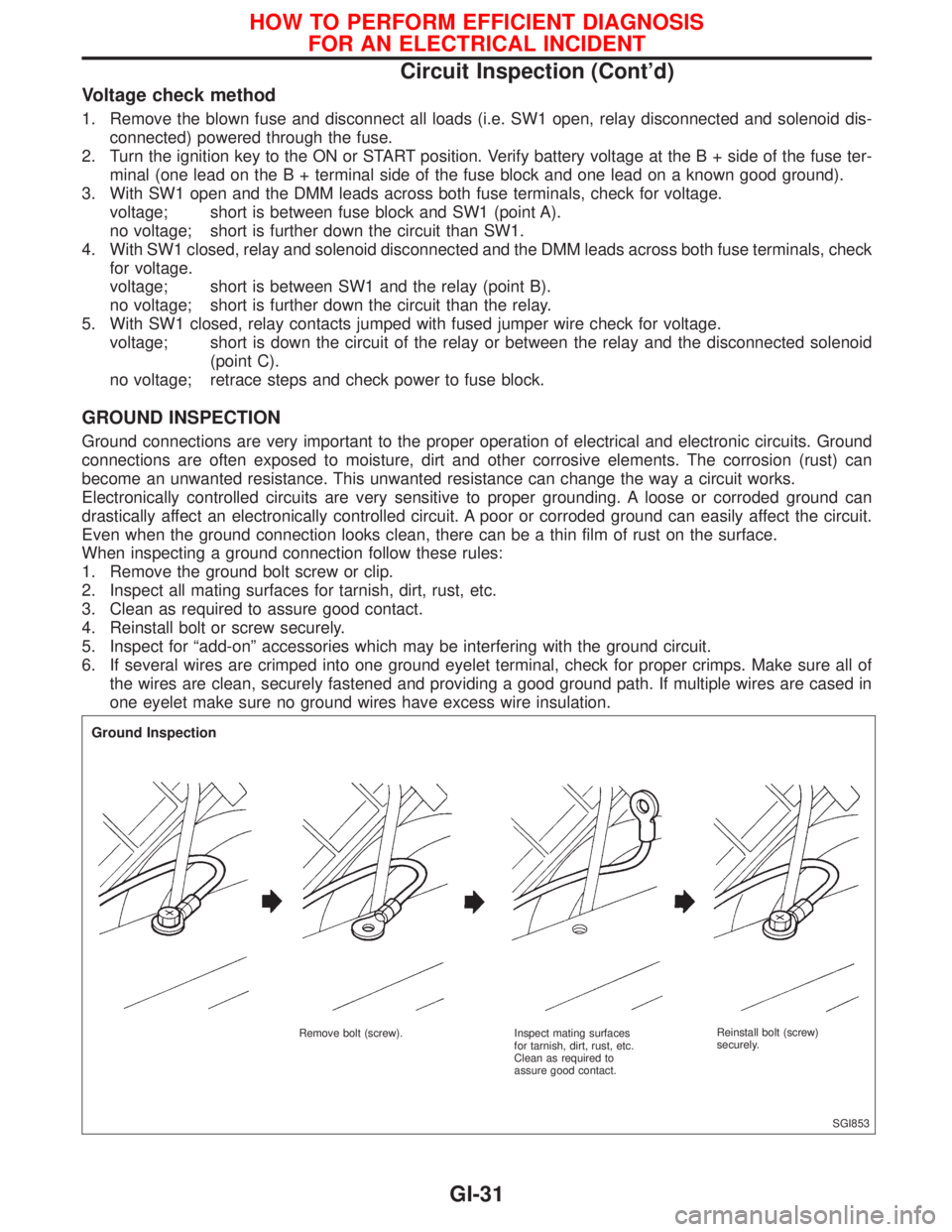
When inspecting a ground connection follow these rules:
1. Remove the ground bolt screw or clip.
2. Inspect all mating surfaces for tarnish, dirt, rust, etc.
3. Clean as required to assure good contact.
4. Reinstall bolt or screw securely.
5. Inspect for ªadd-onº accessories which may be interfering with the ground circuit.
6. If several wires are crimped into one ground eyelet terminal, check for proper crimps. Make sure all of
the wires are clean, securely fastened and providing a good ground path. If multiple wires are cased in
one eyelet make sure no ground wires have excess wire insulation.
SGI853
Ground Inspection
Remove bolt (screw). Inspect mating surfaces
for tarnish, dirt, rust, etc.
Clean as required to
assure good contact.Reinstall bolt (screw)
securely.
HOW TO PERFORM EFFICIENT DIAGNOSIS
FOR AN ELECTRICAL INCIDENT
Circuit Inspection (Cont'd)
GI-31
Page 1827 of 2267
VOLTAGE DROP TESTS
Voltage drop tests are often used to find components or circuits which have excessive resistance. A voltage
drop in a circuit is caused by a resistancewhen the circuit is in operation.
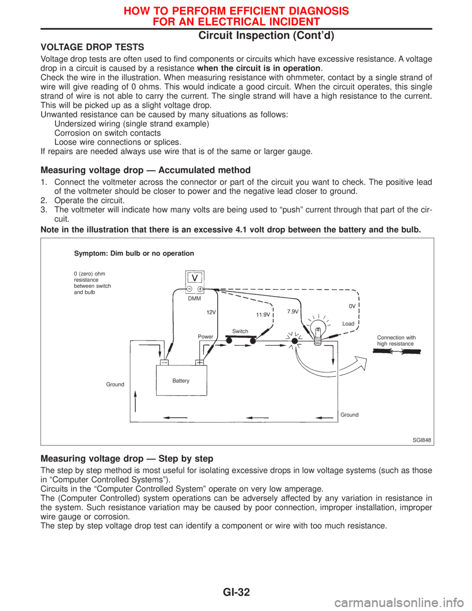
Check the wire in the illustration. When measuring resistance with ohmmeter, contact by a single strand of
wire will give reading of 0 ohms. This would indicate a good circuit. When the circuit operates, this single
strand of wire is not able to carry the current. The single strand will have a high resistance to the current.
This will be picked up as a slight voltage drop.
Unwanted resistance can be caused by many situations as follows:
Undersized wiring (single strand example)
Corrosion on switch contacts
Loose wire connections or splices.
If repairs are needed always use wire that is of the same or larger gauge.
Measuring voltage drop Ð Accumulated method
1. Connect the voltmeter across the connector or part of the circuit you want to check. The positive lead
of the voltmeter should be closer to power and the negative lead closer to ground.
2. Operate the circuit.
3. The voltmeter will indicate how many volts are being used to ªpushº current through that part of the cir-
cuit.
Note in the illustration that there is an excessive 4.1 volt drop between the battery and the bulb.
Measuring voltage drop Ð Step by step
The step by step method is most useful for isolating excessive drops in low voltage systems (such as those
in ªComputer Controlled Systemsº).
Circuits in the ªComputer Controlled Systemº operate on very low amperage.
The (Computer Controlled) system operations can be adversely affected by any variation in resistance in
the system. Such resistance variation may be caused by poor connection, improper installation, improper
wire gauge or corrosion.
The step by step voltage drop test can identify a component or wire with too much resistance.
SGI848
Symptom: Dim bulb or no operation
0 (zero) ohm
resistance
between switch
and bulb
GroundBatteryDMM
PowerSwitchLoad
Connection with
high resistance
Ground
HOW TO PERFORM EFFICIENT DIAGNOSIS
FOR AN ELECTRICAL INCIDENT
Circuit Inspection (Cont'd)
GI-32
Page 1829 of 2267
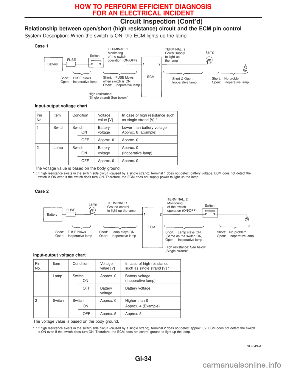
Relationship between open/short (high resistance) circuit and the ECM pin control
System Description: When the switch is ON, the ECM lights up the lamp.
SGI849-A
Case 1
BatteryFUSESwitchTERMINAL: 1
Monitoring
of the switch
operation (ON/OFF)TERMINAL: 2
Power supply
to light up
the lampLamp
Short: FUSE blows.
Open: Inoperative lampShort: FUSE blows
when switch is ON.
Open: Inoperative lamp
High resistance:
(Single strand) See below.*ECM
Short & Open:
Inoperative lampShort: No problem
Open: Inoperative lamp
Case 2
BatteryFUSELampTERMINAL: 1
Ground control
to light up the lampTERMINAL: 2
Monitoring
of the switch
operation (ON/OFF)Switch
Short: FUSE blows.
Open: Inoperative lampShort: Lamp stays ON.
Open: Inoperative lampShort: Lamp stays ON.
(Same as the switch ON)
Open: Inoperative lamp
High resistance: See below.
(Single strand)*Short: No problem
Open: Inoperative lamp ECM
Pin
No.Item Condition Voltage
value [V]In case of high resistance such
as single strand [V] *
1 Switch Switch Battery Lower than battery voltage
ON voltage Approx. 8 (Example)
OFF Approx. 0 Approx. 0
2 Lamp Switch Battery Approx. 0
ON voltage (Inoperative lamp)
OFF Approx. 0 Approx. 0
The voltage value is based on the body ground.
Input-output voltage chart
Pin
No.Item Condition Voltage
value [V]In case of high resistance
such as single strand [V] *
1 Lamp Switch Approx. 0 Battery voltage
ON (Inoperative lamp)
OFF Battery
voltageBattery voltage
2 Switch Switch Approx. 0 Higher than 0
ON Approx. 4 (Example)
OFF Approx. 5 Approx. 5
The voltage value is based on the body ground.
Input-output voltage chart
* : If high resistance exists in the switch side circuit (caused by a single strand), terminal 1 does not detect battery voltage. ECM does not detect the
switch is ON even if the switch does turn ON. Therefore, the ECM does not supply power to light up the lamp.
* : If high resistance exists in the switch side circuit (caused by a single strand), terminal 2 does not detect approx. 0V. ECM does not detect the switch
is ON even if the switch does turn ON. Therefore, the ECM does not control ground to light up the lamp.
HOW TO PERFORM EFFICIENT DIAGNOSIS
FOR AN ELECTRICAL INCIDENT
Circuit Inspection (Cont'd)
GI-34
Page 1833 of 2267
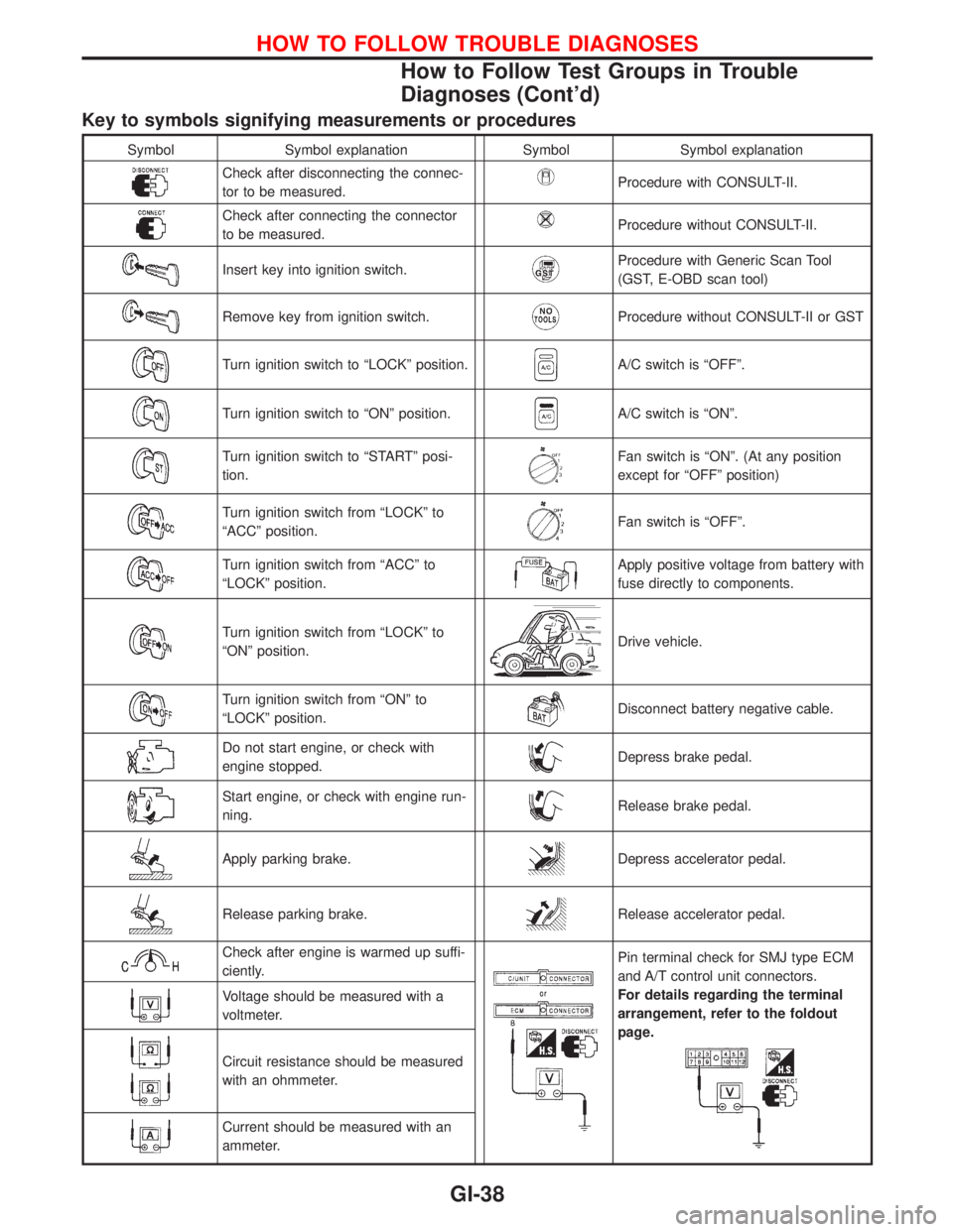
Key to symbols signifying measurements or procedures
Symbol Symbol explanation Symbol Symbol explanation
Check after disconnecting the connec-
tor to be measured.Procedure with CONSULT-II.
Check after connecting the connector
to be measured.Procedure without CONSULT-II.
Insert key into ignition switch.Procedure with Generic Scan Tool
(GST, E-OBD scan tool)
Remove key from ignition switch.Procedure without CONSULT-II or GST
Turn ignition switch to ªLOCKº position.A/C switch is ªOFFº.
Turn ignition switch to ªONº position.A/C switch is ªONº.
Turn ignition switch to ªSTARTº posi-
tion.Fan switch is ªONº. (At any position
except for ªOFFº position)
Turn ignition switch from ªLOCKº to
ªACCº position.Fan switch is ªOFFº.
Turn ignition switch from ªACCº to
ªLOCKº position.Apply positive voltage from battery with
fuse directly to components.
Turn ignition switch from ªLOCKº to
ªONº position.Drive vehicle.
Turn ignition switch from ªONº to
ªLOCKº position.Disconnect battery negative cable.
Do not start engine, or check with
engine stopped.Depress brake pedal.
Start engine, or check with engine run-
ning.Release brake pedal.
Apply parking brake.Depress accelerator pedal.
Release parking brake.Release accelerator pedal.
Check after engine is warmed up suffi-
ciently.Pin terminal check for SMJ type ECM
and A/T control unit connectors.
For details regarding the terminal
arrangement, refer to the foldout
page.
Voltage should be measured with a
voltmeter.
Circuit resistance should be measured
with an ohmmeter.
Current should be measured with an
ammeter.
HOW TO FOLLOW TROUBLE DIAGNOSES
How to Follow Test Groups in Trouble
Diagnoses (Cont'd)
GI-38
Page 1834 of 2267
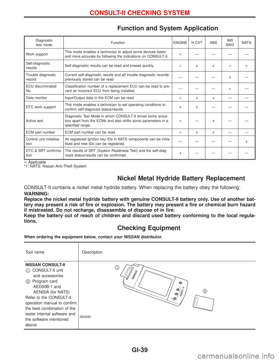
Function and System Application
Diagnostic
test modeFunction ENGINE H×CVT ABSAIR
BAGNATS
Work supportThis mode enables a technician to adjust some devices faster
and more accurate by following the indications on CONSULT-II.´ÐÐÐÐ
Self-diagnostic
resultsSelf-diagnostic results can be read and erased quickly.´xx´´
Trouble diagnostic
recordCurrent self-diagnostic results and all trouble diagnostic records
previously stored can be read.ÐÐÐxÐ
ECU discriminated
No.Classification number of a replacement ECU can be read to pre-
vent an incorrect ECU from being installed.ÐÐдÐ
Data monitor Input/Output data in the ECM can be read.´xxÐÐ
DTC work supportThis mode enables a technician to set operating conditions to
confirm self-diagnosis status/results.x x ÐÐÐ
Active testDiagnostic Test Mode in which CONSULT-II drives some actua-
tors apart from the ECMs and also shifts some parameters in a
specified range.´ÐxÐÐ
ECM part number ECM part number can be read.´xxÐÐ
Control unit initialisa-
tionAll registered ignition key IDs in NATS components can be initia-
lised and new IDs can be registered.ÐÐÐÐ x
DTC & SRT confirma-
tionThe results of SRT (System Readiness Test) and the self-diag-
nosis status/results can be confirmed.x ÐÐÐÐ
´: Applicable
*1: NATS: Nissan Anti-Theft System
Nickel Metal Hydride Battery Replacement
CONSULT-II contains a nickel metal hydride battery. When replacing the battery obey the following:
WARNING:
Replace the nickel metal hydride battery with genuine CONSULT-II battery only. Use of another bat-
tery may present a risk of fire or explosion. The battery may present a fire or chemical burn hazard
if mistreated. Do not recharge, disassemble of dispose of in fire.
Keep the battery out of reach of children and discard used battery conforming to the local regula-
tions.
Checking Equipment
When ordering the equipment below, contact your NISSAN distributor.
Tool name Description
NISSAN CONSULT-II
p1CONSULT-II unit
and accessories
p2Program card
AED00B-1 and
AEN00A (for NATS)
Refer to the CONSULT-II
operation manual to confirm
the best combination of the
tester internal software and
the software mentioned
above.
NGI045
p1
p2
CONSULT-II CHECKING SYSTEM
GI-39
Page 1835 of 2267
NOTE:
lThe CONSULT-II must be used in conjunction with a program card.
CONSULT-II does not require loading (Initialisation) procedure.
lBe sure the CONSULT-II is turned off before installing or removing a program card.
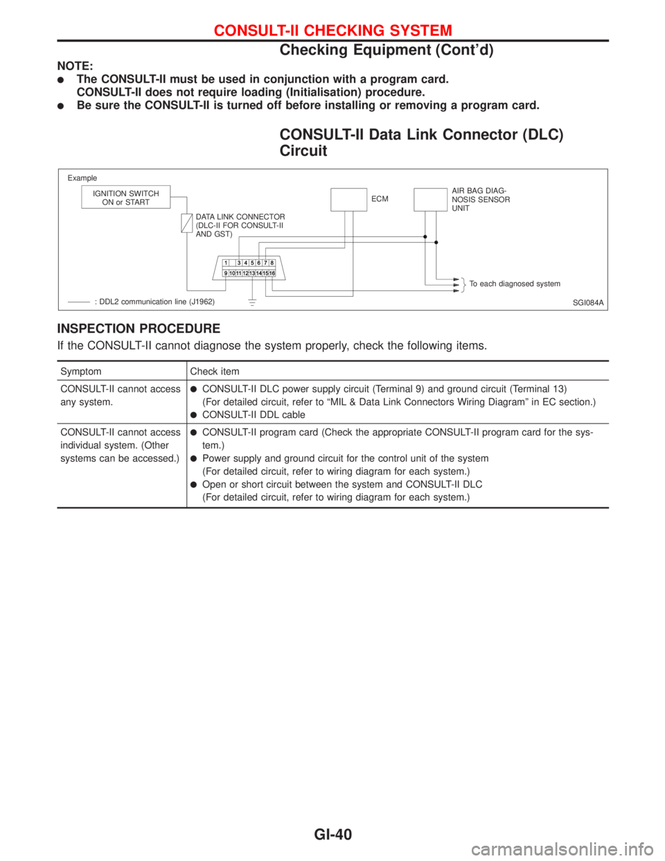
CONSULT-II Data Link Connector (DLC)
Circuit
INSPECTION PROCEDURE
If the CONSULT-II cannot diagnose the system properly, check the following items.
Symptom Check item
CONSULT-II cannot access
any system.
lCONSULT-II DLC power supply circuit (Terminal 9) and ground circuit (Terminal 13)
(For detailed circuit, refer to ªMIL & Data Link Connectors Wiring Diagramº in EC section.)
lCONSULT-II DDL cable
CONSULT-II cannot access
individual system. (Other
systems can be accessed.)
lCONSULT-II program card (Check the appropriate CONSULT-II program card for the sys-
tem.)
lPower supply and ground circuit for the control unit of the system
(For detailed circuit, refer to wiring diagram for each system.)
lOpen or short circuit between the system and CONSULT-II DLC
(For detailed circuit, refer to wiring diagram for each system.)
SGI084A Example
IGNITION SWITCH
ON or START
DATA LINK CONNECTOR
(DLC-II FOR CONSULT-II
AND GST)ECMAIR BAG DIAG-
NOSIS SENSOR
UNIT
To each diagnosed system
: DDL2 communication line (J1962)
CONSULT-II CHECKING SYSTEM
Checking Equipment (Cont'd)
GI-40
Page 1846 of 2267
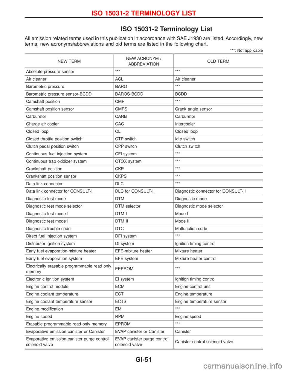
ISO 15031-2 Terminology List
All emission related terms used in this publication in accordance with SAE J1930 are listed. Accordingly, new
terms, new acronyms/abbreviations and old terms are listed in the following chart.
***: Not applicable
NEW TERMNEW ACRONYM /
ABBREVIATIONOLD TERM
Absolute pressure sensor *** ***
Air cleaner ACL Air cleaner
Barometric pressure BARO ***
Barometric pressure sensor-BCDD BAROS-BCDD BCDD
Camshaft position CMP ***
Camshaft position sensor CMPS Crank angle sensor
Carburetor CARB Carburetor
Charge air cooler CAC Intercooler
Closed loop CL Closed loop
Closed throttle position switch CTP switch Idle switch
Clutch pedal position switch CPP switch Clutch switch
Continuous fuel injection system CFI system ***
Continuous trap oxidizer system CTOX system ***
Crankshaft position CKP ***
Crankshaft position sensor CKPS ***
Data link connector DLC ***
Data link connector for CONSULT-II DLC for CONSULT-II Diagnostic connector for CONSULT-II
Diagnostic test mode DTM Diagnostic mode
Diagnostic test mode selector DTM selector Diagnostic mode selector
Diagnostic test mode I DTM I Mode I
Diagnostic test mode II DTM II Mode II
Diagnostic trouble code DTC Malfunction code
Direct fuel injection system DFI system ***
Distributor ignition system DI system Ignition timing control
Early fuel evaporation-mixture heater EFE-mixture heater Mixture heater
Early fuel evaporation system EFE system Mixture heater control
Electrically erasable programmable read only
memoryEEPROM ***
Electronic ignition system EI system Ignition timing control
Engine control module ECM Engine control unit
Engine coolant temperature ECT Engine temperature
Engine coolant temperature sensor ECTS Engine temperature sensor
Engine modification EM ***
Engine speed RPM Engine speed
Erasable programmable read only memory EPROM ***
Evaporative emission canister or Canister EVAP canister or Canister Canister
Evaporative emission canister purge control
solenoid valveEVAP canister purge control
solenoid valveCanister control solenoid valve
ISO 15031-2 TERMINOLOGY LIST
GI-51