Page 1891 of 2267
Wiring Diagram Ð A/C Ð
YHA338
IGNITION SWITCH
ON or START
FUSE
BLOCK
(J/B)Refer to EL-POWER
To EL-ILL
SIDE
LIGHTSIDE
LIGHTA/C
CONTROL
PANEL
To HA-A/C-03
A/C
AUTO
AMP
REFER TO THE FOLLOWING
FUSE BLOCK - Junction Box (J/B)
TROUBLE DIAGNOSESAUTO
HA-42
Page 1895 of 2267
YHA341
IGNITION SWITCH
ON
FUSE
BLOCK (J/B)Refer to EL-POWER.
To HA-A/C-07
Next page
To HA-A/C-07
To HA-A/C-09
Next page
AIR MIX
DOOR
MOTOR
A/C AUTO
AMP.
REFER TO THE FOLLOWING
FUSE BLOCK - Junction Box (J/B)
FUSE BLOCK - Junction Box (J/B) : With diesel engine
: With GA engine
:With GA engine or diesel engine
: With SR engine or QG engineA/C CON-
TROL
PANEL Next page
To HA-A/C-07 INTAKE
DOOR
MOTORTHERMISTORTHERMO
CONTROL
AMPLIFER
TROUBLE DIAGNOSESAUTO
Wiring Diagram Ð A/C Ð (Cont'd)
HA-46
Page 1900 of 2267
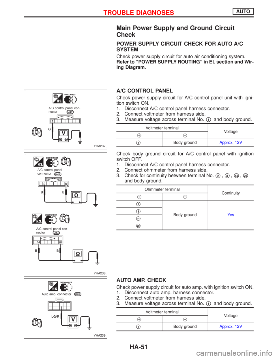
Main Power Supply and Ground Circuit
Check
POWER SUPPLY CIRCUIT CHECK FOR AUTO A/C
SYSTEM
Check power supply circuit for auto air conditioning system.
Refer to ªPOWER SUPPLY ROUTINGº in EL section and Wir-
ing Diagram.
A/C CONTROL PANEL
Check power supply circuit for A/C control panel unit with igni-
tion switch ON.
1. Disconnect A/C control panel harness connector.
2. Connect voltmeter from harness side.
3. Measure voltage across terminal No.
p1and body ground.
Voltmeter terminal
Voltage
!@
p1Body groundApprox. 12V
Check body ground circuit for A/C control panel with ignition
switch OFF.
1. Disconnect A/C control panel harness connector.
2. Connect ohmmeter from harness side.
3. Check for continuity between terminal No.
p2,p8,p14,p20
and body ground.
Ohmmeter terminal
Continuity
!@
p2
Body groundYe sp8
p14
p20
AUTO AMP. CHECK
Check power supply circuit for auto amp. with ignition switch ON.
1. Disconnect auto amp. harness connector.
2. Connect voltmeter from harness side.
3. Measure voltage across terminal No.
p1and body ground.
Voltmeter terminal
Voltage
!@
p1Body groundApprox. 12V
YHA237 A/C control panel con-
nector
YHA238 A/C control panel
connector
A/C control panel con-
nector
YHA239 Auto amp. connector
TROUBLE DIAGNOSESAUTO
HA-51
Page 1902 of 2267
pA
CHECK RESISTOR AFTER DISCON-
NECTING IT.
OK
ENG
Replace resistor.
CHECK FAN SWITCH. (Refer to Elec-
trical Components Inspection.) (HA-78)
OK
ENG
Replace A/C control
panel.
Note
Check circuit continuity between fan
switch harness terminal No.
p2,
p8,p14,p20and body ground.
Check body ground circuit for A/C
control panel. (Refer to Main Power
Supply and Ground Circuit Check,
HA-51).
OK
Replace blower motor.
Note:
If the result is NG or No after checking circuit continuity, repair harness or
connector.
NHA447
A/C Control
panel connectorH
H
H
H
TROUBLE DIAGNOSESAUTO
Diagnostic Procedure 1 (Cont'd)
HA-53
Page 1903 of 2267
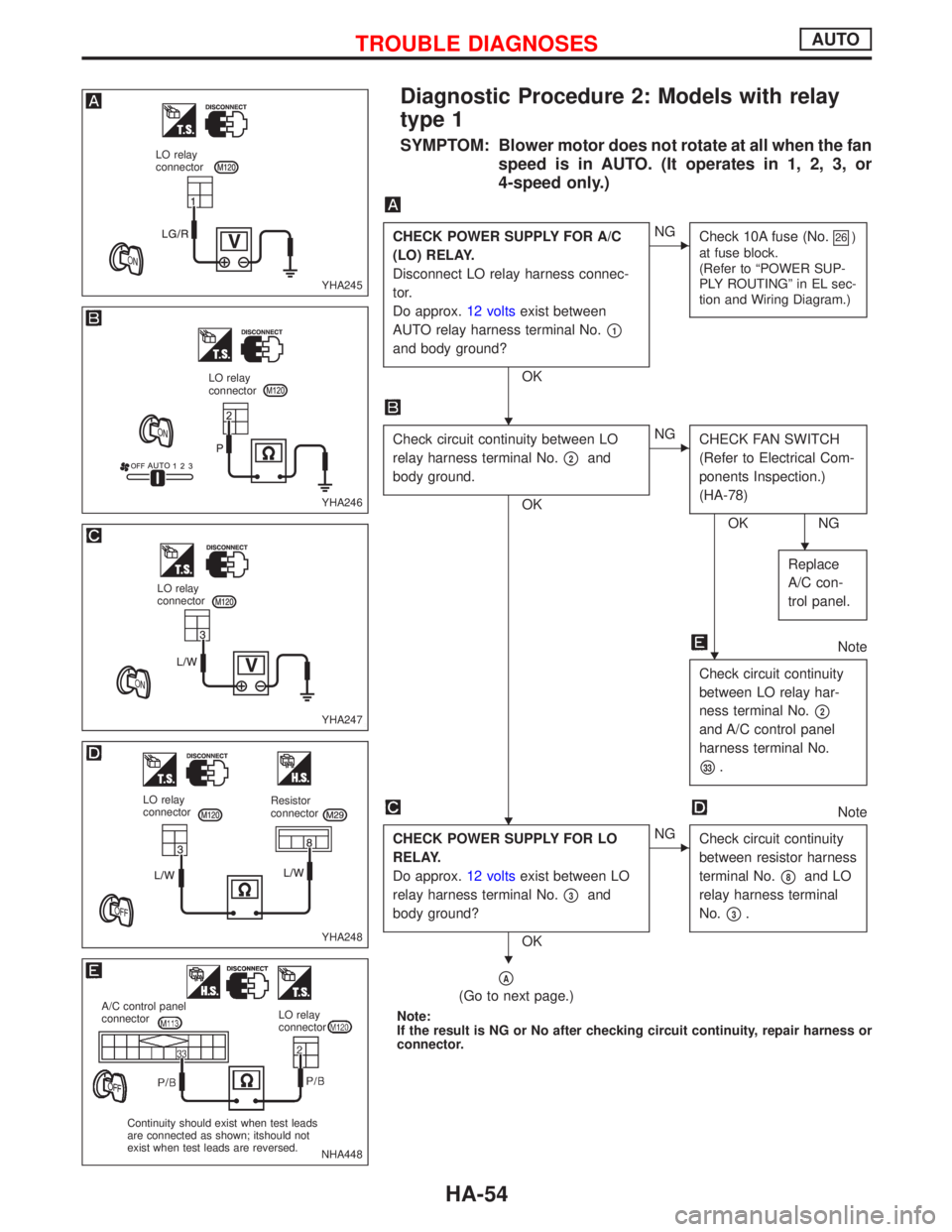
Diagnostic Procedure 2: Models with relay
type 1
SYMPTOM: Blower motor does not rotate at all when the fan
speed is in AUTO. (It operates in 1, 2, 3, or
4-speed only.)
CHECK POWER SUPPLY FOR A/C
(LO) RELAY.
Disconnect LO relay harness connec-
tor.
Do approx.12 voltsexist between
AUTO relay harness terminal No.
p1
and body ground?
OK
ENG
Check 10A fuse (No.26)
at fuse block.
(Refer to ªPOWER SUP-
PLY ROUTINGº in EL sec-
tion and Wiring Diagram.)
Check circuit continuity between LO
relay harness terminal No.
p2and
body ground.
OK
ENG
CHECK FAN SWITCH
(Refer to Electrical Com-
ponents Inspection.)
(HA-78)
OK NG
Replace
A/C con-
trol panel.
Note
Check circuit continuity
between LO relay har-
ness terminal No.
p2
and A/C control panel
harness terminal No.
p33.
Note
CHECK POWER SUPPLY FOR LO
RELAY.
Do approx.12 voltsexist between LO
relay harness terminal No.
p3and
body ground?
OK
ENG
Check circuit continuity
between resistor harness
terminal No.
p8and LO
relay harness terminal
No.
p3.
pA
(Go to next page.)
Note:
If the result is NG or No after checking circuit continuity, repair harness or
connector.
YHA245
LO relay
connector
YHA246
LO relay
connector
YHA247
LO relay
connector
YHA248
LO relay
connectorResistor
connector
NHA448
A/C control panel
connectorLO relay
connector
Continuity should exist when test leads
are connected as shown; itshould not
exist when test leads are reversed.
H
H
H
H
H
TROUBLE DIAGNOSESAUTO
HA-54
Page 1905 of 2267
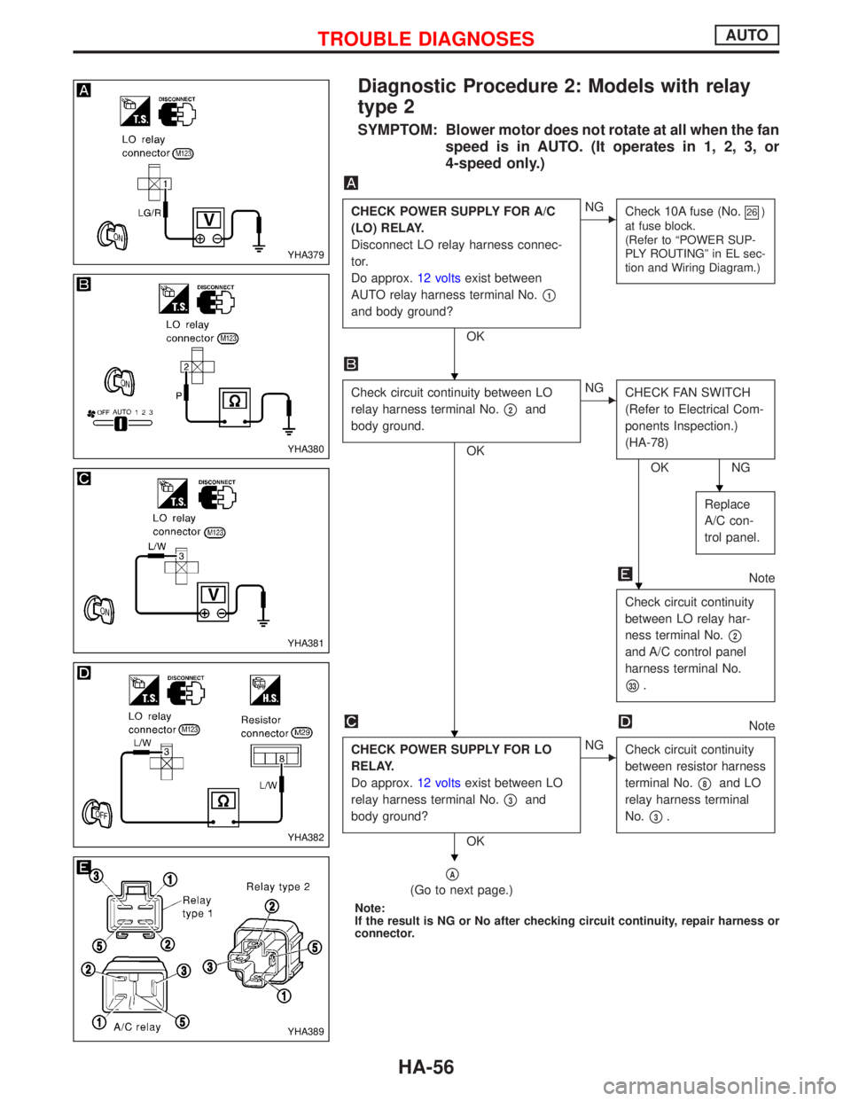
Diagnostic Procedure 2: Models with relay
type 2
SYMPTOM: Blower motor does not rotate at all when the fan
speed is in AUTO. (It operates in 1, 2, 3, or
4-speed only.)
CHECK POWER SUPPLY FOR A/C
(LO) RELAY.
Disconnect LO relay harness connec-
tor.
Do approx.12 voltsexist between
AUTO relay harness terminal No.
p1
and body ground?
OK
ENG
Check 10A fuse (No.26)
at fuse block.
(Refer to ªPOWER SUP-
PLY ROUTINGº in EL sec-
tion and Wiring Diagram.)
Check circuit continuity between LO
relay harness terminal No.
p2and
body ground.
OK
ENG
CHECK FAN SWITCH
(Refer to Electrical Com-
ponents Inspection.)
(HA-78)
OK NG
Replace
A/C con-
trol panel.
Note
Check circuit continuity
between LO relay har-
ness terminal No.
p2
and A/C control panel
harness terminal No.
p33.
Note
CHECK POWER SUPPLY FOR LO
RELAY.
Do approx.12 voltsexist between LO
relay harness terminal No.
p3and
body ground?
OK
ENG
Check circuit continuity
between resistor harness
terminal No.
p8and LO
relay harness terminal
No.
p3.
pA
(Go to next page.)
Note:
If the result is NG or No after checking circuit continuity, repair harness or
connector.
YHA379
YHA380
YHA381
YHA382
YHA389
H
H
H
H
H
TROUBLE DIAGNOSESAUTO
HA-56
Page 1906 of 2267
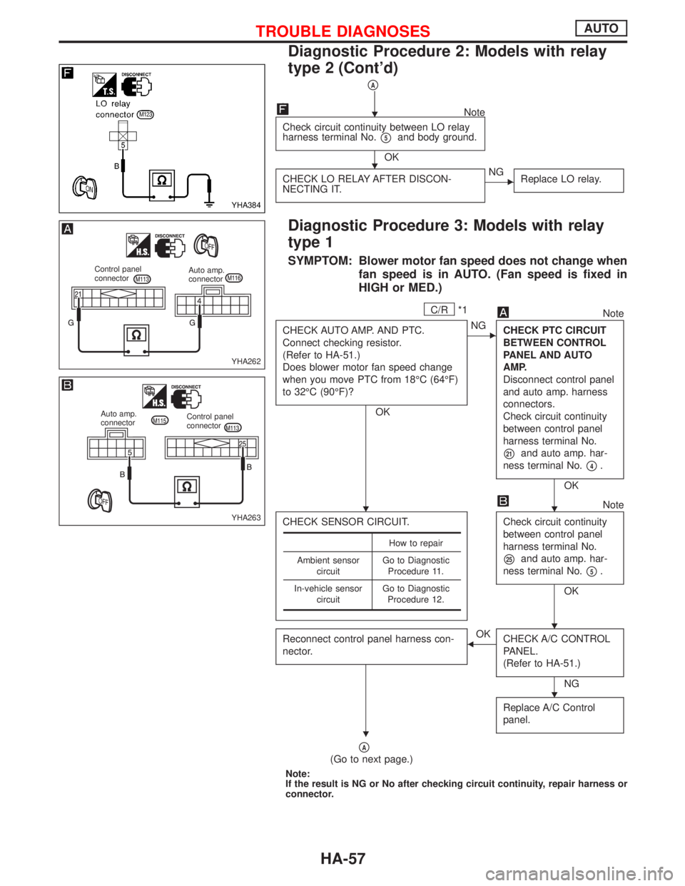
pA
Note
Check circuit continuity between LO relay
harness terminal No.
p5and body ground.
OK
CHECK LO RELAY AFTER DISCON-
NECTING IT.
ENG
Replace LO relay.
Diagnostic Procedure 3: Models with relay
type 1
SYMPTOM: Blower motor fan speed does not change when
fan speed is in AUTO. (Fan speed is fixed in
HIGH or MED.)
C/R*1Note
CHECK AUTO AMP. AND PTC.
Connect checking resistor.
(Refer to HA-51.)
Does blower motor fan speed change
when you move PTC from 18ÉC (64ÉF)
to 32ÉC (90ÉF)?
OK
ENG
CHECK PTC CIRCUIT
BETWEEN CONTROL
PANEL AND AUTO
AMP.
Disconnect control panel
and auto amp. harness
connectors.
Check circuit continuity
between control panel
harness terminal No.
p21and auto amp. har-
ness terminal No.
p4.
OK
CHECK SENSOR CIRCUIT.
Note
Check circuit continuity
between control panel
harness terminal No.
p25and auto amp. har-
ness terminal No.
p5.
OK
Reconnect control panel harness con-
nector.
FOK
CHECK A/C CONTROL
PANEL.
(Refer to HA-51.)
NG
Replace A/C Control
panel.
pA
(Go to next page.)
Note:
If the result is NG or No after checking circuit continuity, repair harness or
connector.
How to repair
Ambient sensor
circuitGo to Diagnostic
Procedure 11.
In-vehicle sensor
circuitGo to Diagnostic
Procedure 12.
YHA384
YHA262
Control panel
connectorAuto amp.
connector
YHA263
Auto amp.
connectorControl panel
connector
H
H
HH
H
H
H
TROUBLE DIAGNOSESAUTO
Diagnostic Procedure 2: Models with relay
type 2 (Cont'd)
HA-57
Page 1908 of 2267
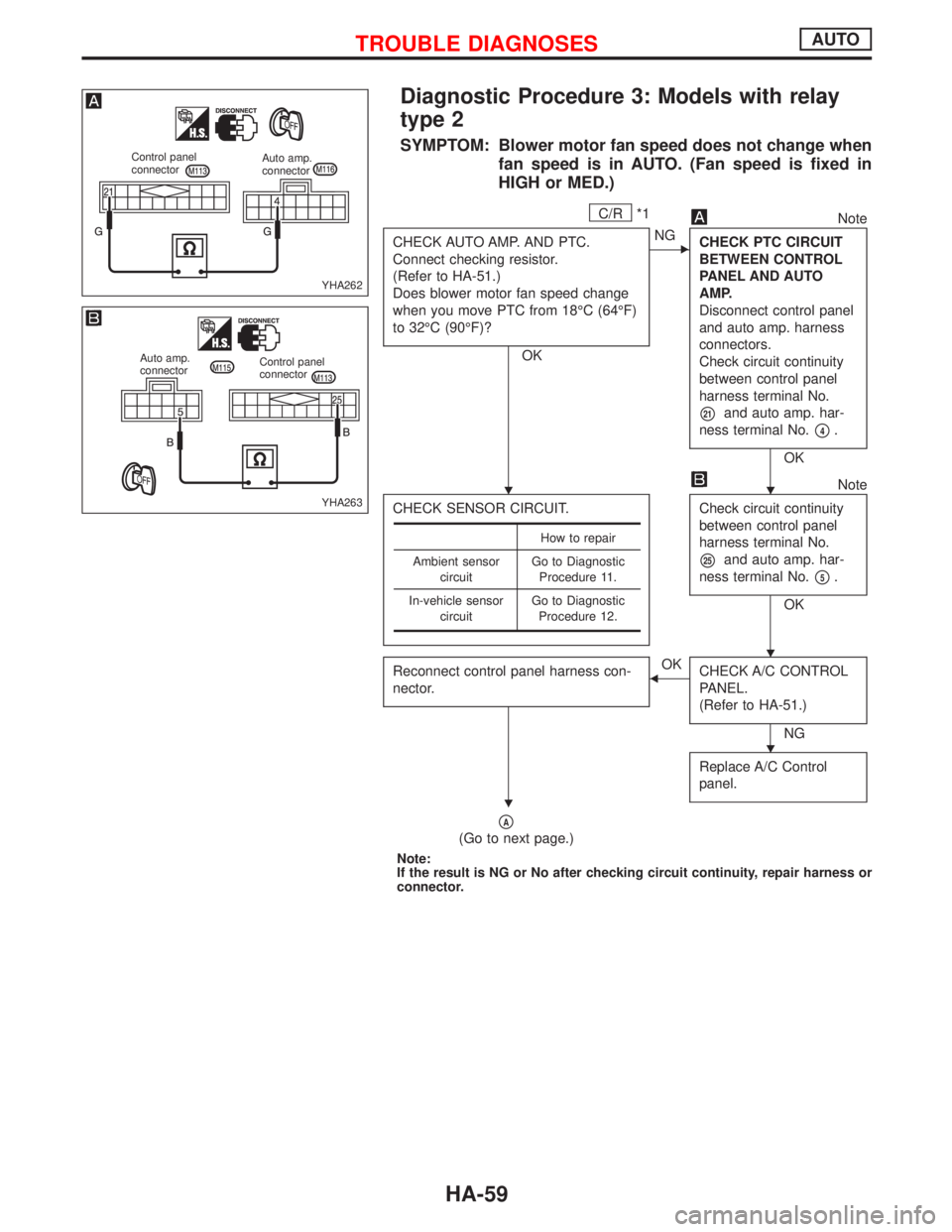
Diagnostic Procedure 3: Models with relay
type 2
SYMPTOM: Blower motor fan speed does not change when
fan speed is in AUTO. (Fan speed is fixed in
HIGH or MED.)
C/R*1Note
CHECK AUTO AMP. AND PTC.
Connect checking resistor.
(Refer to HA-51.)
Does blower motor fan speed change
when you move PTC from 18ÉC (64ÉF)
to 32ÉC (90ÉF)?
OK
ENG
CHECK PTC CIRCUIT
BETWEEN CONTROL
PANEL AND AUTO
AMP.
Disconnect control panel
and auto amp. harness
connectors.
Check circuit continuity
between control panel
harness terminal No.
p21and auto amp. har-
ness terminal No.
p4.
OK
CHECK SENSOR CIRCUIT.
Note
Check circuit continuity
between control panel
harness terminal No.
p25and auto amp. har-
ness terminal No.
p5.
OK
Reconnect control panel harness con-
nector.
FOK
CHECK A/C CONTROL
PANEL.
(Refer to HA-51.)
NG
Replace A/C Control
panel.
pA
(Go to next page.)
Note:
If the result is NG or No after checking circuit continuity, repair harness or
connector.
How to repair
Ambient sensor
circuitGo to Diagnostic
Procedure 11.
In-vehicle sensor
circuitGo to Diagnostic
Procedure 12.
YHA262
Control panel
connectorAuto amp.
connector
YHA263
Auto amp.
connectorControl panel
connector
HH
H
H
H
TROUBLE DIAGNOSESAUTO
HA-59