Page 1873 of 2267
Operational Check
The purpose of the operational check is to confirm that the sys-
tem operates as it should. The systems which are checked are
the blower, mode (discharge air), intake air, temperature
decrease, temperature increase.
CONDITIONS:
Engine running at normal operating temperature.
PROCEDURE:
1. Check blower
1) Turn fan control knob to 1-speed.
Blower should operate on 1-speed.
2) Then turn fan control knob to 2-speed.
3) Continue checking blower speed until all four speeds are
checked.
4) Leave blower on 4-speed.
2. Check discharge air
1) Turn mode control knob.
2) Confirm that discharge air comes out according to the air
distribution table at left.
Refer to ªDischarge Air Flowº in ªDESCRIPTIONº (HA-23).
KHA106
KHA107
KHA032 Discharge airflow
Switch
mode/
indicatorAiroutlet/distribution
Face Foot Defroster
100% Ð Ð
60% 40% Ð
15%* 65% 20%
15%* 55% 30%
15%* Ð 85%
* Face air from SIDE VENT only
TROUBLE DIAGNOSESHEATER
HA-24
Page 1874 of 2267
3. Check recirculation
1) Press recirculation switch.
Recirculation indicator should light.
2) Listen for intake door position change (you should hear
blower sound change slightly).
4. Check temperature decrease
1) Turn temperature control knob to full cold.
2) Check for cold air at discharge air outlets.
5. Check temperature increase
1) Turn temperature control knob to full hot.
2) Check for hot air at discharge air outlets.
KHA108
KHA109
KHA110
TROUBLE DIAGNOSESHEATER
Operational Check (Cont'd)
HA-25
Page 1877 of 2267

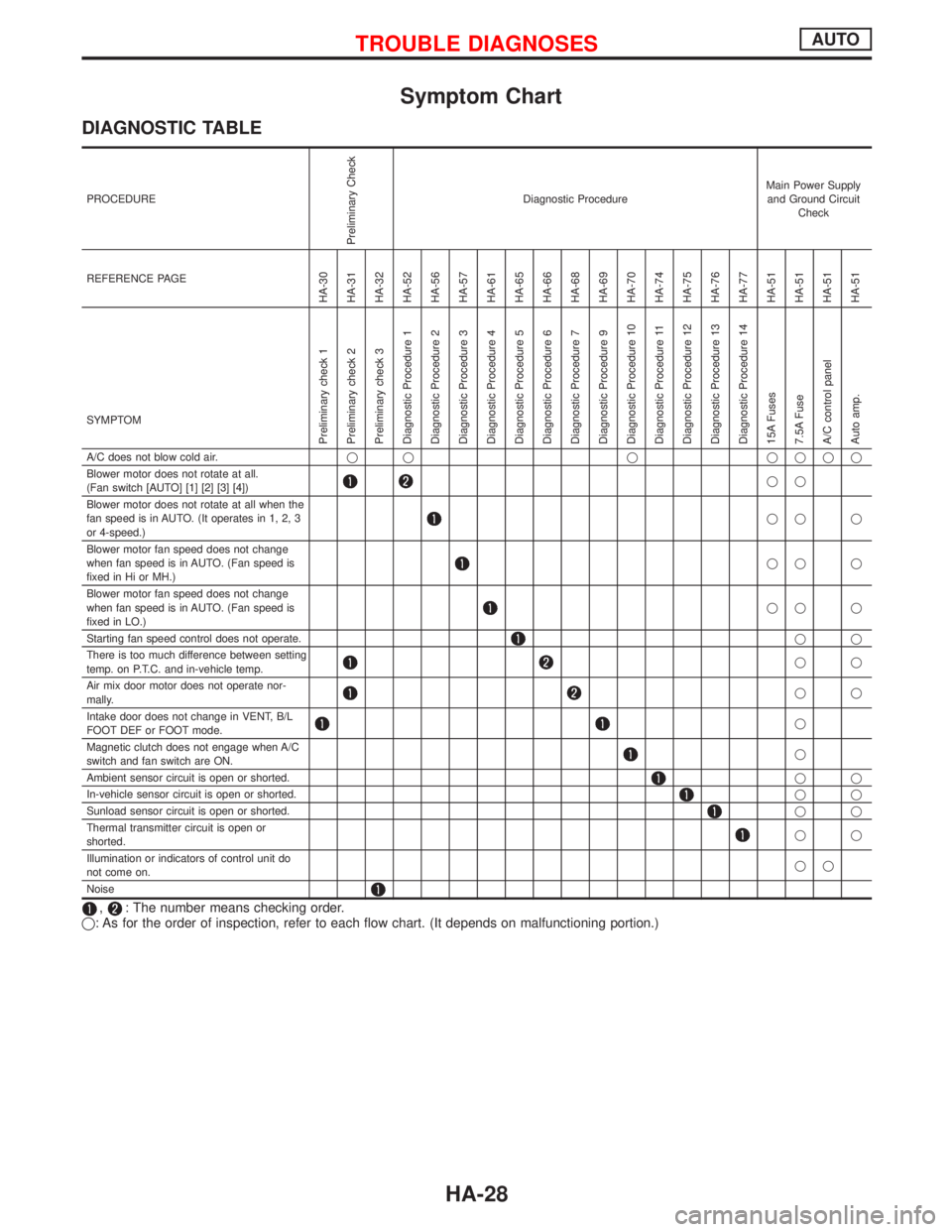
Symptom Chart
DIAGNOSTIC TABLE
PROCEDURE
Preliminary Check
Diagnostic ProcedureMain Power Supply
and Ground Circuit
Check
REFERENCE PAGE
HA-30
HA-31
HA-32
HA-52
HA-56
HA-57
HA-61
HA-65
HA-66
HA-68
HA-69
HA-70
HA-74
HA-75
HA-76
HA-77
HA-51
HA-51
HA-51
HA-51
SYMPTOM
Preliminary check 1
Preliminary check 2
Preliminary check 3
Diagnostic Procedure 1
Diagnostic Procedure 2
Diagnostic Procedure 3
Diagnostic Procedure 4
Diagnostic Procedure 5
Diagnostic Procedure 6
Diagnostic Procedure 7
Diagnostic Procedure 9
Diagnostic Procedure 10
Diagnostic Procedure 11
Diagnostic Procedure 12
Diagnostic Procedure 13
Diagnostic Procedure 14
15A Fuses
7.5A Fuse
A/C control panel
Auto amp.
A/C does not blow cold air.q q q qqqq
Blower motor does not rotate at all.
(Fan switch [AUTO] [1] [2] [3] [4])
qq
Blower motor does not rotate at all when the
fan speed is in AUTO. (It operates in 1, 2, 3
or 4-speed.)
qq q
Blower motor fan speed does not change
when fan speed is in AUTO. (Fan speed is
fixed in Hi or MH.)
qq q
Blower motor fan speed does not change
when fan speed is in AUTO. (Fan speed is
fixed in LO.)
qq q
Starting fan speed control does not operate.
qq
There is too much difference between setting
temp. on P.T.C. and in-vehicle temp.
qq
Air mix door motor does not operate nor-
mally.
qq
Intake door does not change in VENT, B/L
FOOT DEF or FOOT mode.
q
Magnetic clutch does not engage when A/C
switch and fan switch are ON.
q
Ambient sensor circuit is open or shorted.
qq
In-vehicle sensor circuit is open or shorted.
qq
Sunload sensor circuit is open or shorted.
qq
Thermal transmitter circuit is open or
shorted.
qq
Illumination or indicators of control unit do
not come on.qq
Noise
,: The number means checking order.
q: As for the order of inspection, refer to each flow chart. (It depends on malfunctioning portion.)
TROUBLE DIAGNOSESAUTO
HA-28
Page 1878 of 2267
Electrical Components Inspection
Ð
Ð
Ð
Ð
Ð
HA-84
HA-93
HA-94
HA-81
HA-51
HA-86
HA-85
HA-86Refer to
EL section.HA-87
HA-98
HA-98
HA-98
HA-98
HA-80
HA-79
HA-70
HA-113Refer to
EC section.
Refer to
EL section.Ð Blower motor
Fan resistor
Control
unit
Air mix door
PBR
Intake door motor
Auto amp.
Ambient sensor
In-vehicle sensor
Sunload sensor
Thermal transmitter
A/C relay
LO relay
ML relay
MH relay
HI relay
Thermo control amp.
Pressure switch/sensor
Com-
pressor
ECM
Illumination system
Harness A/C switch
REC switch
Fan switch
PTC
Magnetic clutch
Thermal protector
q qq qqqqqqqqq q qqqq q
qq qq
q q q q qqqq q
qq q q qq q
qq q q q q q
qq q q qq
qqq qqqqq
qq qqqqq
qqq
q q q qqqqq q
qq
qq
qq
qq
qqqqq
TROUBLE DIAGNOSESAUTO
Symptom Chart (Cont'd)
HA-29
Page 1880 of 2267

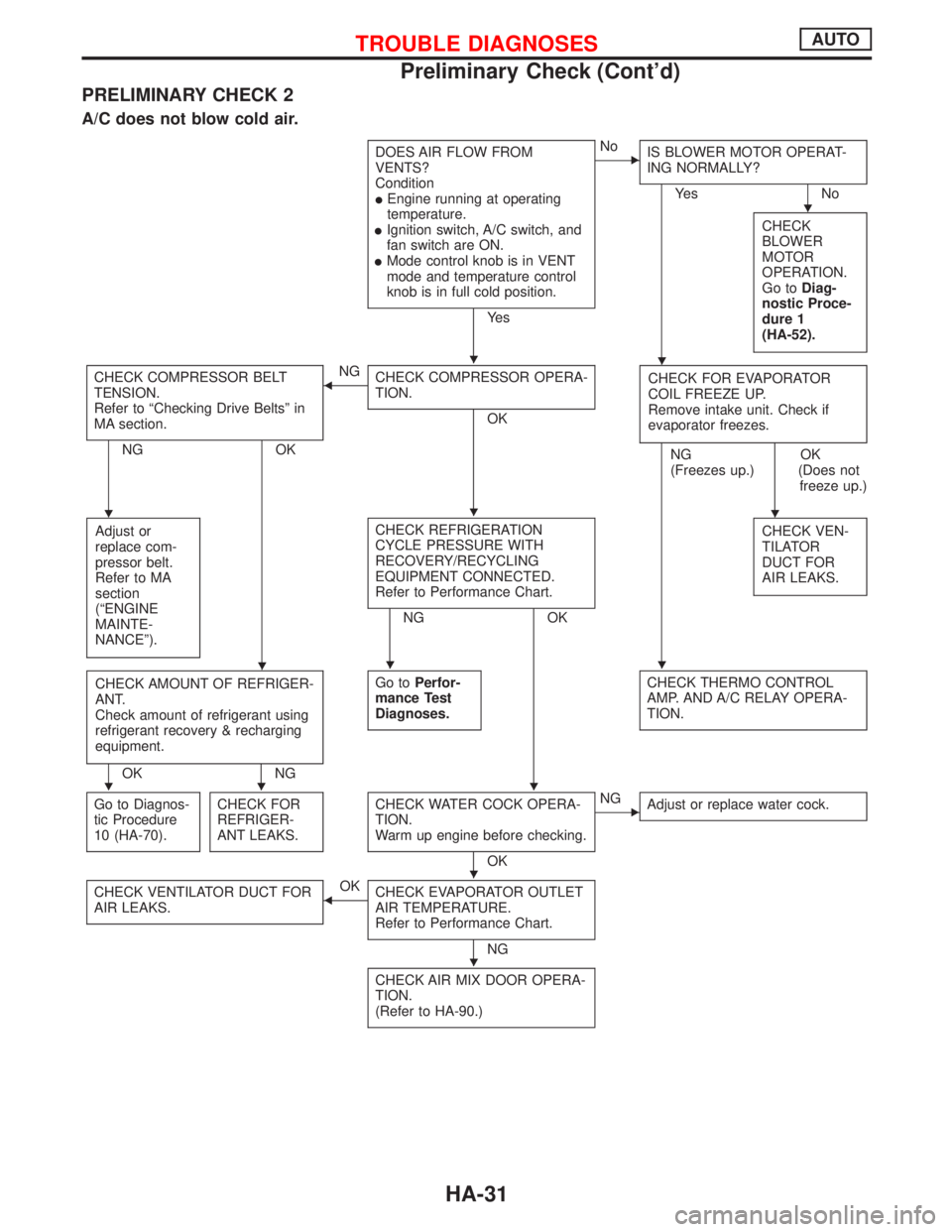
PRELIMINARY CHECK 2
A/C does not blow cold air.
DOES AIR FLOW FROM
VENTS?
Condition
lEngine running at operating
temperature.
lIgnition switch, A/C switch, and
fan switch are ON.
lMode control knob is in VENT
mode and temperature control
knob is in full cold position.
Ye s
ENo
IS BLOWER MOTOR OPERAT-
ING NORMALLY?
Ye s N o
CHECK
BLOWER
MOTOR
OPERATION.
Go toDiag-
nostic Proce-
dure 1
(HA-52).
CHECK COMPRESSOR BELT
TENSION.
Refer to ªChecking Drive Beltsº in
MA section.
NG OK
FNG
CHECK COMPRESSOR OPERA-
TION.
OKCHECK FOR EVAPORATOR
COIL FREEZE UP.
Remove intake unit. Check if
evaporator freezes.
NG
(Freezes up.)OK
(Does not
freeze up.)
Adjust or
replace com-
pressor belt.
Refer to MA
section
(ªENGINE
MAINTE-
NANCEº).
CHECK REFRIGERATION
CYCLE PRESSURE WITH
RECOVERY/RECYCLING
EQUIPMENT CONNECTED.
Refer to Performance Chart.
NG OKCHECK VEN-
TILATOR
DUCT FOR
AIR LEAKS.
CHECK AMOUNT OF REFRIGER-
ANT.
Check amount of refrigerant using
refrigerant recovery & recharging
equipment.
OK NGGo toPerfor-
mance Test
Diagnoses.
CHECK THERMO CONTROL
AMP. AND A/C RELAY OPERA-
TION.
Go to Diagnos-
tic Procedure
10 (HA-70).CHECK FOR
REFRIGER-
ANT LEAKS.CHECK WATER COCK OPERA-
TION.
Warm up engine before checking.
OK
ENG
Adjust or replace water cock.
CHECK VENTILATOR DUCT FOR
AIR LEAKS.FOK
CHECK EVAPORATOR OUTLET
AIR TEMPERATURE.
Refer to Performance Chart.
NG
CHECK AIR MIX DOOR OPERA-
TION.
(Refer to HA-90.)
H
HH
HHH
HHH
HHH
H
H
TROUBLE DIAGNOSESAUTO
Preliminary Check (Cont'd)
HA-31
Page 1882 of 2267

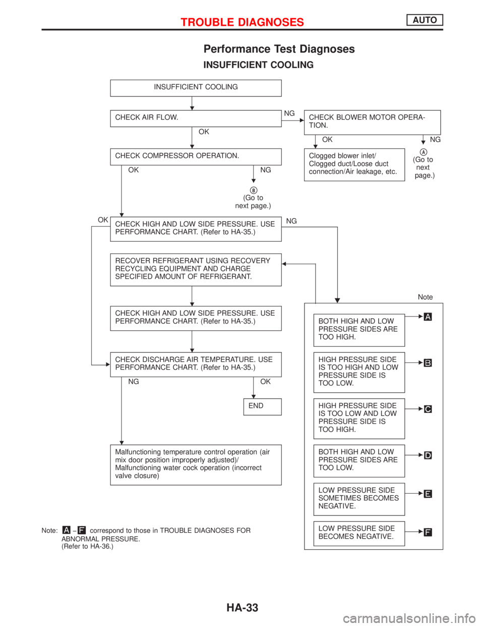
Performance Test Diagnoses
INSUFFICIENT COOLING
INSUFFICIENT COOLING
CHECK AIR FLOW.
OK
ENG
CHECK BLOWER MOTOR OPERA-
TION.
OK NG
CHECK COMPRESSOR OPERATION.
OK NGClogged blower inlet/
Clogged duct/Loose duct
connection/Air leakage, etc.
pA(Go to
next
page.)
pB(Go to
next page.)
OK
CHECK HIGH AND LOW SIDE PRESSURE. USE
PERFORMANCE CHART. (Refer to HA-35.)NG
H RECOVER REFRIGERANT USING RECOVERY
RECYCLING EQUIPMENT AND CHARGE
SPECIFIED AMOUNT OF REFRIGERANT.
F
Note
CHECK HIGH AND LOW SIDE PRESSURE. USE
PERFORMANCE CHART. (Refer to HA-35.)
BOTH HIGH AND LOW
PRESSURE SIDES ARE
TOO HIGH.E
ECHECK DISCHARGE AIR TEMPERATURE. USE
PERFORMANCE CHART. (Refer to HA-35.)
NG OKHIGH PRESSURE SIDE
IS TOO HIGH AND LOW
PRESSURE SIDE IS
TOO LOW.
E
ENDHIGH PRESSURE SIDE
IS TOO LOW AND LOW
PRESSURE SIDE IS
TOO HIGH.E
Malfunctioning temperature control operation (air
mix door position improperly adjusted)/
Malfunctioning water cock operation (incorrect
valve closure)BOTH HIGH AND LOW
PRESSURE SIDES ARE
TOO LOW.E
LOW PRESSURE SIDE
SOMETIMES BECOMES
NEGATIVE.E
LOW PRESSURE SIDE
BECOMES NEGATIVE.ENote:þcorrespond to those in TROUBLE DIAGNOSES FOR
ABNORMAL PRESSURE.
(Refer to HA-36.)
H
HHH
H
H
H
H
H
H
TROUBLE DIAGNOSESAUTO
HA-33
Page 1888 of 2267
Component Location
NHA290
In-vehicle sensorA/C control
panel
Sunload sensorA/C relay
.Triple-pressure switch
(With dieselengine)
Dual-pressure switch (With GA engine)
Pressure sensor (SRand QG engine)Ambient sensor
Compressor
Blower motor
fan resistor
.Auto amp.
HI.ML.LH.LO
relayBlower fan
motor relay
Compressor
.Ambient sensor
.
A/C relay
.Fuse block (J/B)
.Blower fan motor relaylBehind fuse block (J/B)
.
.Auto amp.
.MH relayLO relay
.ML relay.HI relay
Air mix door motor
Blower motor
Fan resistor.
Intake door motor
Sunload
sensor.
A/C control panel
.
.In-vehicle sensor
.Dual-pressure
switch/sensor
.Triple-pressure switch
Intake door
motor
Air mix
door motor
TROUBLE DIAGNOSESAUTO
HA-39
Page 1890 of 2267
Circuit Diagram Ð Air Conditioner
YHA337
IGNITION SWITCH
ON
FUSE
BLOWER
MOTORINTAKE
DOOR
MOTORTo illumination
systemCOMBINATION
METER
(WATER TEM-
PERATURE
GAUGE)IGNITION SWITCH
ON or START
FUSEFUSIBLE
LINKBATTERY
FUSIBLE
LINK
COOLING
FA N
MOTOR-1
THERMO
CONTROL
AMPLIFIERAIR CONDI-
TIONER
RELAYCOOLING
FA N
RELAY-1COOLING
FA N
RELAY-2COOLING
FA N
RELAY-3
TRIPLE-
PRESSURE
SWITCH
COOL-
ING FAN
RELAY-1
DUAL-
PRESSURE
SWITCH
COOLING
FA N
MOTOR-1COOLING
FA N
MOTOR-2COOLING
FA N
MOTOR-2
: With gasoline engine
: With diesel engine
: With GA engine
: With SR engine or
QG engine
: With GA engine or
diesel engine IACV-FIDC
SOLENOID
VA LV E THERMAL PRO-
TECTOR
COMPRESSOR THERMAL
TRANSMITTER A/C AUTO AMPIN-
VEHICLE
SENSORA/C CON-
TROL
PANEL
REFRIGENT
PRESSURE
SENSOR AMBIENT
SENSOR SUN LOAD
SENSOR A/C HIGH
RELAY
A/C MH
RELAY
A/C ML
RELAY
A/C LOW
RELAY FA N
RESISTOR
AIR MIX
DOOR
MOTOR
TROUBLE DIAGNOSESAUTO
HA-41