1999 NISSAN PRIMERA Control
[x] Cancel search: ControlPage 1847 of 2267
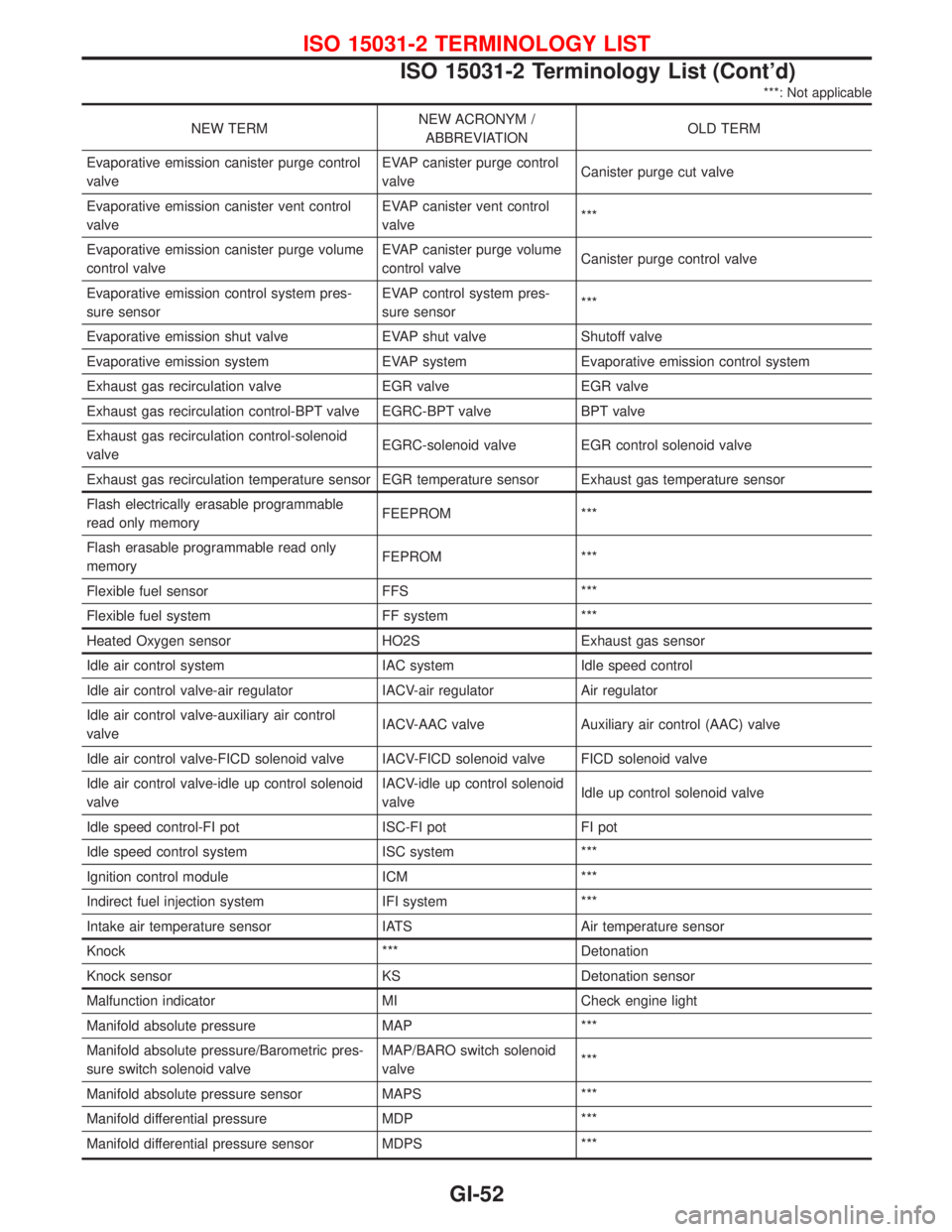
***: Not applicable
NEW TERMNEW ACRONYM /
ABBREVIATIONOLD TERM
Evaporative emission canister purge control
valveEVAP canister purge control
valveCanister purge cut valve
Evaporative emission canister vent control
valveEVAP canister vent control
valve***
Evaporative emission canister purge volume
control valveEVAP canister purge volume
control valveCanister purge control valve
Evaporative emission control system pres-
sure sensorEVAP control system pres-
sure sensor***
Evaporative emission shut valve EVAP shut valve Shutoff valve
Evaporative emission system EVAP system Evaporative emission control system
Exhaust gas recirculation valve EGR valve EGR valve
Exhaust gas recirculation control-BPT valve EGRC-BPT valve BPT valve
Exhaust gas recirculation control-solenoid
valveEGRC-solenoid valve EGR control solenoid valve
Exhaust gas recirculation temperature sensor EGR temperature sensor Exhaust gas temperature sensor
Flash electrically erasable programmable
read only memoryFEEPROM ***
Flash erasable programmable read only
memoryFEPROM ***
Flexible fuel sensor FFS ***
Flexible fuel system FF system ***
Heated Oxygen sensor HO2S Exhaust gas sensor
Idle air control system IAC system Idle speed control
Idle air control valve-air regulator IACV-air regulator Air regulator
Idle air control valve-auxiliary air control
valveIACV-AAC valve Auxiliary air control (AAC) valve
Idle air control valve-FICD solenoid valve IACV-FICD solenoid valve FICD solenoid valve
Idle air control valve-idle up control solenoid
valveIACV-idle up control solenoid
valveIdle up control solenoid valve
Idle speed control-FI pot ISC-FI pot FI pot
Idle speed control system ISC system ***
Ignition control module ICM ***
Indirect fuel injection system IFI system ***
Intake air temperature sensor IATS Air temperature sensor
Knock *** Detonation
Knock sensor KS Detonation sensor
Malfunction indicator MI Check engine light
Manifold absolute pressure MAP ***
Manifold absolute pressure/Barometric pres-
sure switch solenoid valveMAP/BARO switch solenoid
valve***
Manifold absolute pressure sensor MAPS ***
Manifold differential pressure MDP ***
Manifold differential pressure sensor MDPS ***
ISO 15031-2 TERMINOLOGY LIST
ISO 15031-2 Terminology List (Cont'd)
GI-52
Page 1848 of 2267
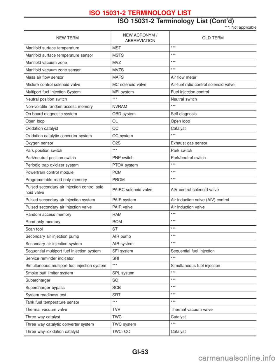
***: Not applicable
NEW TERMNEW ACRONYM /
ABBREVIATIONOLD TERM
Manifold surface temperature MST ***
Manifold surface temperature sensor MSTS ***
Manifold vacuum zone MVZ ***
Manifold vacuum zone sensor MVZS ***
Mass air flow sensor MAFS Air flow meter
Mixture control solenoid valve MC solenoid valve Air-fuel ratio control solenoid valve
Multiport fuel injection System MFI system Fuel injection control
Neutral position switch *** Neutral switch
Non-volatile random access memory NVRAM ***
On-board diagnostic system OBD system Self-diagnosis
Open loop OL Open loop
Oxidation catalyst OC Catalyst
Oxidation catalytic converter system OC system ***
Oxygen sensor O2S Exhaust gas sensor
Park position switch *** Park switch
Park/neutral position switch PNP switch Park/neutral switch
Periodic trap oxidizer system PTOX system ***
Powertrain control module PCM ***
Programmable read only memory PROM ***
Pulsed secondary air injection control sole-
noid valvePAIRC solenoid valve AIV control solenoid valve
Pulsed secondary air injection system PAIR system Air induction valve (AIV) control
Pulsed secondary air injection valve PAIR valve Air induction valve
Random access memory RAM ***
Read only memory ROM ***
Scan tool ST ***
Secondary air injection pump AIR pump ***
Secondary air injection system AIR system ***
Sequential multiport fuel injection system SFI system Sequential fuel injection
Service reminder indicator SRI ***
Simultaneous multiport fuel injection system *** Simultaneous fuel injection
Smoke puff limiter system SPL system ***
Supercharger SC ***
Supercharger bypass SCB ***
System readiness test SRT ***
Tank fuel temperature sensor *** ***
Thermal vacuum valve TVV Thermal vacuum valve
Three way catalyst TWC Catalyst
Three way catalytic converter system TWC system ***
Three way+oxidation catalyst TWC+OC Catalyst
ISO 15031-2 TERMINOLOGY LIST
ISO 15031-2 Terminology List (Cont'd)
GI-53
Page 1849 of 2267

***: Not applicable
NEW TERMNEW ACRONYM /
ABBREVIATIONOLD TERM
Three way + oxidation catalytic converter
systemTWC + OC system ***
Throttle body TB Throttle chamber
SPI body
Throttle body fuel injection system TBI system Fuel injection control
Throttle position TP Throttle position
Throttle position sensor TPS Throttle sensor
Throttle position switch TP switch Throttle switch
Torque converter clutch solenoid valve TCC solenoid valve Lock-up cancel solenoid
Lock-up solenoid
Turbocharger TC Turbocharger
Vacuum cut valve *** Vacuum control valve
Vacuum cut valve bypass valve *** ***
Vehicle speed sensor VSS Vehicle speed sensor
Volume air flow sensor VAFS Air flow meter
Warm up oxidation catalyst WU-OC Catalyst
Warm up oxidation catalytic converter system WU-OC system ***
Warm up three way catalyst WU-TWC Catalyst
Warm up three way catalytic converter sys-
temWU-TWC system ***
Wide open throttle position switch WOTP switch Full switch
ISO 15031-2 TERMINOLOGY LIST
ISO 15031-2 Terminology List (Cont'd)
GI-54
Page 1850 of 2267
HEATER &
AIR CONDITIONER
SECTION
HA
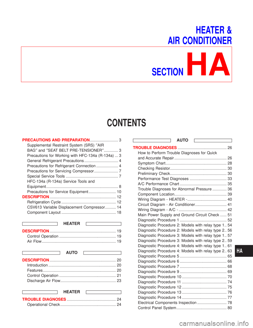
CONTENTS
PRECAUTIONS AND PREPARATION.......................... 3
Supplemental Restraint System (SRS)²AIR
BAG²and²SEAT BELT PRE-TENSIONER²............. 3
Precautions for Working with HFC-134a (R-134a) ... 3
General Refrigerant Precautions ............................... 4
Precautions for Refrigerant Connection .................... 4
Precautions for Servicing Compressor ...................... 7
Special Service Tools ................................................ 7
HFC-134a (R-134a) Service Tools and
Equipment .................................................................. 8
Precautions for Service Equipment ......................... 10
DESCRIPTION............................................................. 12
Refrigeration Cycle .................................................. 12
CSV613 Variable Displacement Compressor.......... 14
Component Layout .................................................. 18
HEATER
DESCRIPTION............................................................. 19
Control Operation .................................................... 19
Air Flow .................................................................... 19
AUTO
DESCRIPTION............................................................. 20
Introduction .............................................................. 20
Features ................................................................... 20
Control Operation .................................................... 21
Discharge Air Flow................................................... 23
HEATER
TROUBLE DIAGNOSES............................................. 24
Operational Check ................................................... 24
AUTO
TROUBLE DIAGNOSES............................................. 26
How to Perform Trouble Diagnoses for Quick
and Accurate Repair ................................................ 26
Symptom Chart ........................................................ 28
Checking Resistor.................................................... 30
Preliminary Check.................................................... 30
Performance Test Diagnoses .................................. 33
A/C Performance Chart ........................................... 35
Trouble Diagnoses for Abnormal Pressure ............. 36
Component Location................................................ 39
Wiring Diagram - HEATER -.................................... 40
Circuit Diagram - Air Conditioner............................. 41
Wiring Diagram - A/C - ............................................ 42
Main Power Supply and Ground Circuit Check ...... 51
Diagnostic Procedure 1 ........................................... 52
Diagnostic Procedure 2: Models with relay type 1.. 54
Diagnostic Procedure 2: Models with relay type 2.. 56
Diagnostic Procedure 3: Models with relay type 1.. 57
Diagnostic Procedure 3: Models with relay type 2.. 59
Diagnostic Procedure 4: Models with relay type 1.. 61
Diagnostic Procedure 4: Models with relay type 2.. 63
Diagnostic Procedure 5 ........................................... 65
Diagnostic Procedure 6 ........................................... 66
Diagnostic Procedure 7 ........................................... 68
Diagnostic Procedure 9 ........................................... 69
Diagnostic Procedure 10 ......................................... 70
Diagnostic Procedure 11 ......................................... 74
Diagnostic Procedure 12 ......................................... 75
Diagnostic Procedure 13 ......................................... 76
Diagnostic Procedure 14 ......................................... 77
Electrical Components Inspection ........................... 78
Control Panel System .............................................. 80
HA
Page 1851 of 2267
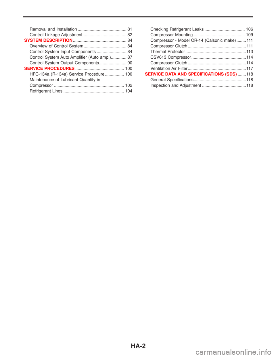
Removal and Installation ......................................... 81
Control Linkage Adjustment..................................... 82
SYSTEM DESCRIPTION............................................. 84
Overview of Control System .................................... 84
Control System Input Components ......................... 84
Control System Auto Amplifier (Auto amp.)............. 87
Control System Output Components....................... 90
SERVICE PROCEDURES......................................... 100
HFC-134a (R-134a) Service Procedure ................ 100
Maintenance of Lubricant Quantity in
Compressor ........................................................... 102
Refrigerant Lines ................................................... 104Checking Refrigerant Leaks .................................. 106
Compressor Mounting ........................................... 109
Compressor - Model CR-14 (Calsonic make) ........ 111
Compressor Clutch ................................................. 111
Thermal Protector ................................................... 113
CSV613 Compressor .............................................. 114
Compressor Clutch ................................................. 114
Ventilation Air Filter ................................................. 117
SERVICE DATA AND SPECIFICATIONS (SDS)....... 118
General Specifications ............................................ 118
Inspection and Adjustment ..................................... 118
HA-2
Page 1860 of 2267
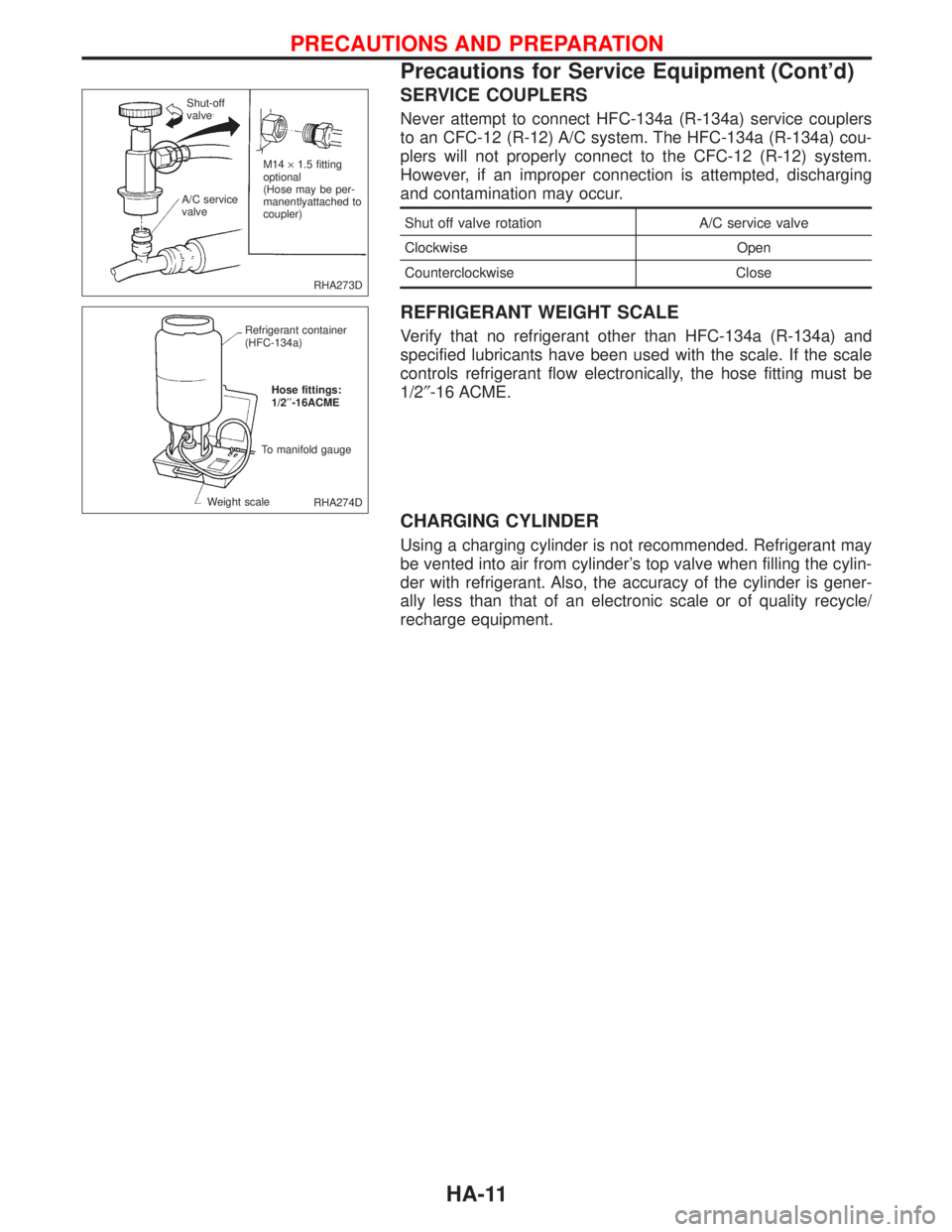
SERVICE COUPLERS
Never attempt to connect HFC-134a (R-134a) service couplers
to an CFC-12 (R-12) A/C system. The HFC-134a (R-134a) cou-
plers will not properly connect to the CFC-12 (R-12) system.
However, if an improper connection is attempted, discharging
and contamination may occur.
Shut off valve rotation A/C service valve
Clockwise Open
Counterclockwise Close
REFRIGERANT WEIGHT SCALE
Verify that no refrigerant other than HFC-134a (R-134a) and
specified lubricants have been used with the scale. If the scale
controls refrigerant flow electronically, the hose fitting must be
1/2²-16 ACME.
CHARGING CYLINDER
Using a charging cylinder is not recommended. Refrigerant may
be vented into air from cylinder's top valve when filling the cylin-
der with refrigerant. Also, the accuracy of the cylinder is gener-
ally less than that of an electronic scale or of quality recycle/
recharge equipment.
RHA273D M14´1.5 fitting
optional
(Hose may be per-
manentlyattached to
coupler) A/C service
valveShut-off
valve
RHA274D Refrigerant container
(HFC-134a)
Hose fittings:
1/2¢¢-16ACME
To manifold gauge
Weight scale
PRECAUTIONS AND PREPARATION
Precautions for Service Equipment (Cont'd)
HA-11
Page 1861 of 2267
Refrigeration Cycle
REFRIGERANT FLOW
The refrigerant flow is in the standard pattern. Refrigerant flows through the compressor, condenser, liquid
tank, evaporator, and back to the compressor.
The refrigerant evaporation through the evaporator coil is controlled by an externally equalized expansion
valve, located inside the evaporator case.
FREEZE PROTECTION
Variable displacement (CSV613)
Under normal operating conditions, when the A/C is switched on, the compressor runs continuously, and the
evaporator pressure, therefore temperature, is controlled by the CSV613 variable displacement compressor
to prevent freeze up.
Vane rotary (CR-14)
The compressor cycles on and off to maintain the evaporator temperature within a specified range. When
the evaporator coil temperature falls below a specified point, the thermo control amplifier interrupts the
compressor operation. When the evaporator coil temperature rises above the specification, the thermo con-
trol amplifier allows compressor operation.
REFRIGERANT SYSTEM PROTECTION
Dual-pressure switch (System with CR-14 compressor)
The refrigerant system is protected against excessively high or low pressure by the dual-pressure switch,
located on the liquid tank. If the system pressure rises above, or falls below the specifications, the dual-
pressure switch opens to interrupt the compressor operation.
Pressure sensor (System with CSV613 compressor)
The pressure sensor is located on the liquid tank. It converts the system pressure into a voltage value witch
is then input into ECM.
If the system pressure rises above, or falls below the specifications, ECM interrupt the compressor opera-
tion.
Fusible plug
Open at temperatures above 105ÉC (221ÉF), thereby discharging refrigerant to the atmosphere. If this plug
is melted and opened, check the refrigerant line and replace liquid tank.
Pressure relief valve (CSV613 compressor)
The refrigerant system is also protected by a pressure relief valve, located in the rear head of the compres-
sor. When the pressure of refrigerant in the system increases to an abnormal level [more than 3,727 kPa
(38 kg/cm
2, 540 psi)], the release port on the pressure relief valve automatically opens and releases refrig-
erant into the atmosphere.
DESCRIPTION
HA-12
Page 1863 of 2267
CSV613 Variable Displacement Compressor
GENERAL INFORMATION
1. The CSV613 compressor differs from previous units. The vent temperatures of the CSV613 compress
or do not drop too far below 5ÉC (41ÉF) when:
levaporator intake air temperature is less than 20ÉC (68ÉF)
lengine is running at speeds less than 1,500 rpm.
This is because the CSV613 compressor provides a means of ªcapacityº control.
2. The CSV613 compressor provides refrigerant control under varying conditions. During cold winters, it
may not produce high refrigerant pressure discharge (compared to previous units) when used with air
conditioning systems.
3. A ªclankingº sound may occasionally be heard during refrigerant charge. The sound indicates that the
tilt angle of the swash plate has changed and is not a problem.
4. For air conditioning systems with the CSV613 compressor, the clutch remains engaged unless: the sys-
tem main switch, fan switch or ignition switch is turned OFF. When ambient (outside) temperatures are
low or when the amount of refrigerant is insufficient, the clutch is disengaged to protect the compressor.
5. A constant range of suction pressure is maintained when engine speed is greater than a certain value.
It normally ranges from 147 to 177 kPa (1.47 to 1.77 bar, 1.5 to 1.8 kg/cm
2, 21 to 26 psi) under vary-
ing conditions.
In previous compressors, however, suction pressure was reduced with increases in engine speed.
DESCRIPTION
HA-14