Page 1792 of 2267
Terminal Arrangement
YEL232C To time control unit
UP
Spare fuse Fuel pump relay
Front fog lamp relay
Rear window defogger relay Power window relay
To air bag harness
To room lamp harness :
To main harness:
Ignition relay
Circuit breaker-1
Blower relayTo main harness
To engine
room harness
: LHD models
: RHD models
To body harness
FUSE BLOCK — Junction Box (J/B)
Page 1794 of 2267
Terminal Arrangement
YEL233C
TCM (Transmission control module)
ABS CONTROL UNIT
ECM (SR engine and QG engine)
ECM (CD engine)TCM (Transmission control module)
ELECTRICAL UNITS
Page 1796 of 2267

GENERAL INFORMATION
SECTION
GI
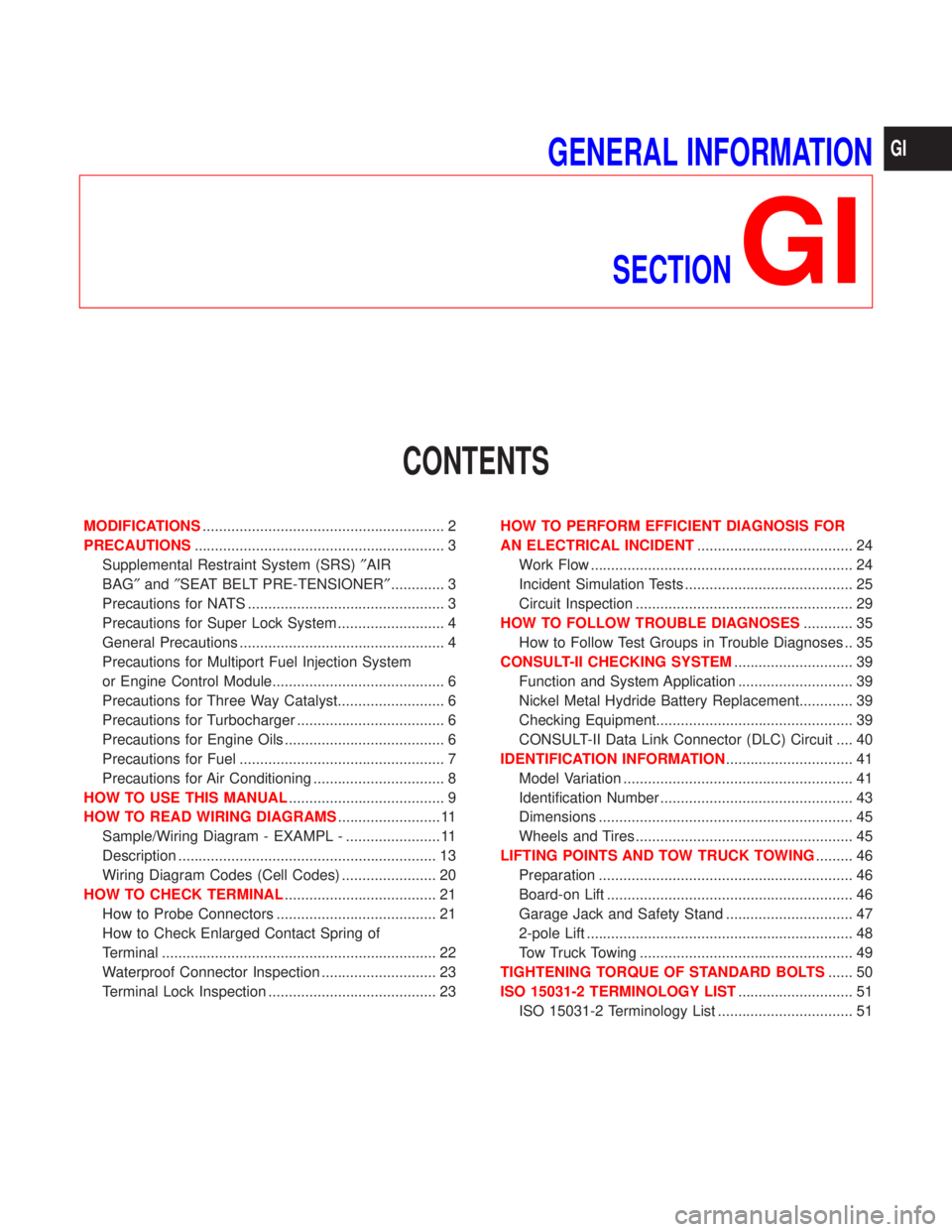
CONTENTS
MODIFICATIONS........................................................... 2
PRECAUTIONS............................................................. 3
Supplemental Restraint System (SRS)²AIR
BAG²and²SEAT BELT PRE-TENSIONER²............. 3
Precautions for NATS ................................................ 3
Precautions for Super Lock System .......................... 4
General Precautions .................................................. 4
Precautions for Multiport Fuel Injection System
or Engine Control Module.......................................... 6
Precautions for Three Way Catalyst.......................... 6
Precautions for Turbocharger .................................... 6
Precautions for Engine Oils ....................................... 6
Precautions for Fuel .................................................. 7
Precautions for Air Conditioning ................................ 8
HOW TO USE THIS MANUAL...................................... 9
HOW TO READ WIRING DIAGRAMS......................... 11
Sample/Wiring Diagram - EXAMPL - ....................... 11
Description ............................................................... 13
Wiring Diagram Codes (Cell Codes) ....................... 20
HOW TO CHECK TERMINAL..................................... 21
How to Probe Connectors ....................................... 21
How to Check Enlarged Contact Spring of
Terminal ................................................................... 22
Waterproof Connector Inspection ............................ 23
Terminal Lock Inspection ......................................... 23HOW TO PERFORM EFFICIENT DIAGNOSIS FOR
AN ELECTRICAL INCIDENT...................................... 24
Work Flow ................................................................ 24
Incident Simulation Tests ......................................... 25
Circuit Inspection ..................................................... 29
HOW TO FOLLOW TROUBLE DIAGNOSES............ 35
How to Follow Test Groups in Trouble Diagnoses .. 35
CONSULT-II CHECKING SYSTEM............................. 39
Function and System Application ............................ 39
Nickel Metal Hydride Battery Replacement............. 39
Checking Equipment................................................ 39
CONSULT-II Data Link Connector (DLC) Circuit .... 40
IDENTIFICATION INFORMATION............................... 41
Model Variation ........................................................ 41
Identification Number ............................................... 43
Dimensions .............................................................. 45
Wheels and Tires ..................................................... 45
LIFTING POINTS AND TOW TRUCK TOWING......... 46
Preparation .............................................................. 46
Board-on Lift ............................................................ 46
Garage Jack and Safety Stand ............................... 47
2-pole Lift ................................................................. 48
Tow Truck Towing .................................................... 49
TIGHTENING TORQUE OF STANDARD BOLTS...... 50
ISO 15031-2 TERMINOLOGY LIST............................ 51
ISO 15031-2 Terminology List ................................. 51
GI
Page 1797 of 2267
APPLIED FROM:
SJN *** P11U 0526000
* : Any of the possibilities. See Vehicle Identification Number Arrangement.
OUTLINE OF MODIFICATIONS
GENERAL
lVarious running changes on engine control system, electrical systems, body etc. Note that the introduc-
tion timing of some of the running changes may not be entirely in line with the above mentioned VIN.
lFor some running changes, the VIN (Vehicle Identification Number) is mentioned to specify the timing
of the change implemention.
The VIN No. may not be an exact number, there is an error range of approx. 50 cars.
MODIFICATIONS
GI-2
Page 1799 of 2267

Regarding the procedures of NATS initialisation and NATS igni-
tion key ID registration, refer to CONSULT-II operation manual
for NATS.
Therefore, CONSULT-II NATS software (program card and
operation manual) must be kept strictly confidential to main-
tain the integrity of the anti-theft function.
lWhen servicing NATS (trouble diagnoses, system initialisa-
tion and additional registration of other NATS ignition key
IDs), it may be necessary to re-register original key identifi-
cation. Therefore, be sure to obtain all keys from vehicle
owner.
A maximum of four key IDs can be registered into NATS.
Precautions for Super Lock System
Locking the driver's door or front passenger's door with the key
or remote control will lock all doors and activate the Super Lock
System.
The Super Lock System is designed to prevent theft as it can
only be released when a front door is unlocked using a key or
remote control.
This means, none of the door locks can be operated from the
inside using the door lock knob when the Super Lock System is
activated.
General Precautions
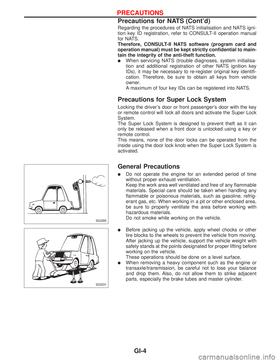
lDo not operate the engine for an extended period of time
without proper exhaust ventilation.
Keep the work area well ventilated and free of any flammable
materials. Special care should be taken when handling any
flammable or poisonous materials, such as gasoline, refrig-
erant gas, etc. When working in a pit or other enclosed area,
be sure to properly ventilate the area before working with
hazardous materials.
Do not smoke while working on the vehicle.
lBefore jacking up the vehicle, apply wheel chocks or other
tire blocks to the wheels to prevent the vehicle from moving.
After jacking up the vehicle, support the vehicle weight with
safety stands at the points designated for proper lifting before
working on the vehicle.
These operations should be done on a level surface.
lWhen removing a heavy component such as the engine or
transaxle/transmission, be careful not to lose your balance
and drop them. Also, do not allow them to strike adjacent
parts, especially the brake tubes and master cylinder.
SGI285
SGI231
PRECAUTIONS
Precautions for NATS (Cont'd)
GI-4
Page 1801 of 2267

Precautions for Multiport Fuel Injection
System or Engine Control Module
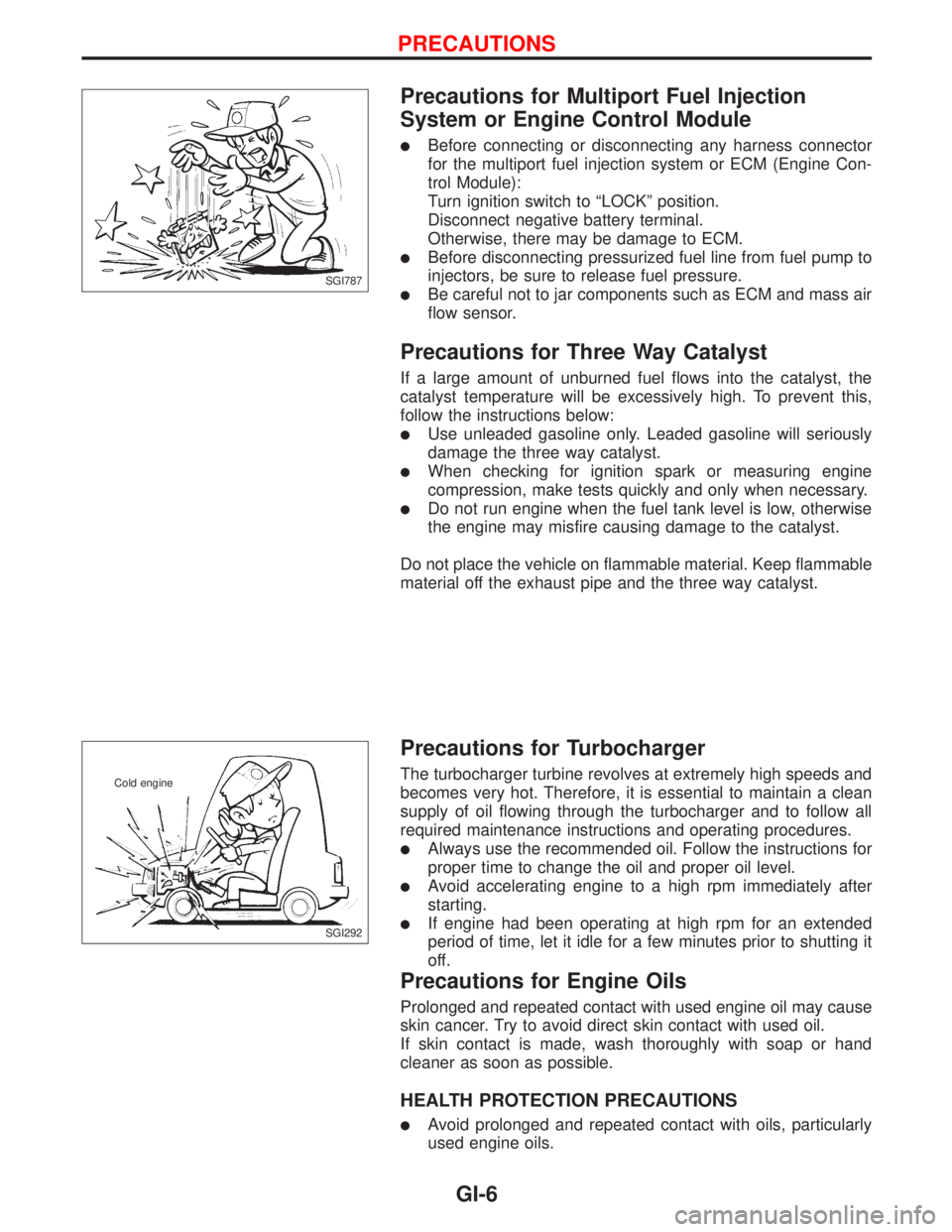
lBefore connecting or disconnecting any harness connector
for the multiport fuel injection system or ECM (Engine Con-
trol Module):
Turn ignition switch to ªLOCKº position.
Disconnect negative battery terminal.
Otherwise, there may be damage to ECM.
lBefore disconnecting pressurized fuel line from fuel pump to
injectors, be sure to release fuel pressure.
lBe careful not to jar components such as ECM and mass air
flow sensor.
Precautions for Three Way Catalyst
If a large amount of unburned fuel flows into the catalyst, the
catalyst temperature will be excessively high. To prevent this,
follow the instructions below:
lUse unleaded gasoline only. Leaded gasoline will seriously
damage the three way catalyst.
lWhen checking for ignition spark or measuring engine
compression, make tests quickly and only when necessary.
lDo not run engine when the fuel tank level is low, otherwise
the engine may misfire causing damage to the catalyst.
Do not place the vehicle on flammable material. Keep flammable
material off the exhaust pipe and the three way catalyst.
Precautions for Turbocharger
The turbocharger turbine revolves at extremely high speeds and
becomes very hot. Therefore, it is essential to maintain a clean
supply of oil flowing through the turbocharger and to follow all
required maintenance instructions and operating procedures.
lAlways use the recommended oil. Follow the instructions for
proper time to change the oil and proper oil level.
lAvoid accelerating engine to a high rpm immediately after
starting.
lIf engine had been operating at high rpm for an extended
period of time, let it idle for a few minutes prior to shutting it
off.
Precautions for Engine Oils
Prolonged and repeated contact with used engine oil may cause
skin cancer. Try to avoid direct skin contact with used oil.
If skin contact is made, wash thoroughly with soap or hand
cleaner as soon as possible.
HEALTH PROTECTION PRECAUTIONS
lAvoid prolonged and repeated contact with oils, particularly
used engine oils.
SGI787
SGI292 Cold engine
PRECAUTIONS
GI-6
Page 1806 of 2267
Sample/Wiring Diagram Ð EXAMPL Ð
lFor Description, refer to GI-13.
YGI001
Refer to optional splice. BATTERY
Preceding
page
RELAY
MOTOR
MOTOR
CONTROL
MODULE
A/T models
M/T models
.REFER TO THE FOLLOWINGM1,E103FUSE BLOCK -
Junction Box (J/B)
M2FUSE BLOCK -
Junction Box (J/B)
E127FUSE BLOCK -
Junction Box (J/B) POWER JOINT
CONNECTOR-1
SWITCHTo EL-
EXAMPL
Next page
To GI-
EXAMPL-04
DIODE
POSITION
APOSITION
BSIGNAL
GND GNDUNIT
HOW TO READ WIRING DIAGRAMS
GI-11
Page 1812 of 2267
DETECTABLE LINES AND NON-DETECTABLE LINES
In some wiring diagrams, two kinds of lines, representing wires,
with different weight are used.
lA line with regular weight (wider line) represents a ªdetect-
able line for DTC (Diagnostic Trouble Code)º. A ªdetectable
line for DTCº is a circuit in which ECM (Engine Control Mod-
ule) can detect its malfunctions with the on-board diagnostic
system.
lA line with less weight (thinner line) represents a ªnon-detect-
able line for DTCº. A ªnon-detectable line for DTCº is a cir-
cuit in which ECM cannot detect its malfunctions with the
on-board diagnostic system.
SGI862
IGNITION SWITCH
ON or START
VEHICLE
SPEED
SENSOR
SPEED
OMETER
M27Detectable line
for DTC
Non-detectable
line for DTC
ECM
(ENGINE CONTROL MODULE)
HOW TO READ WIRING DIAGRAMS
Description (Cont'd)
GI-17