Page 1481 of 2267

Trouble Diagnoses
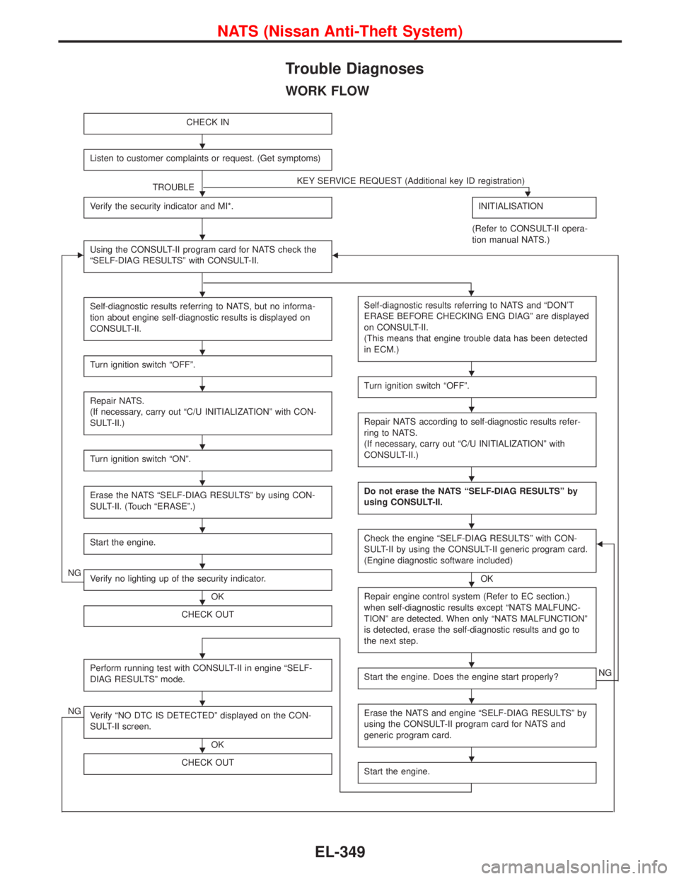
WORK FLOW
CHECK IN
Listen to customer complaints or request. (Get symptoms)
TROUBLEKEY SERVICE REQUEST (Additional key ID registration)�
Verify the security indicator and MI*.INITIALISATION
(Refer to CONSULT-II opera-
tion manual NATS.)
�Using the CONSULT-II program card for NATS check the
“SELF-DIAG RESULTS”with CONSULT-II.�
Self-diagnostic results referring to NATS, but no informa-
tion about engine self-diagnostic results is displayed on
CONSULT-II.
Turn ignition switch“OFF”.
Repair NATS.
(If necessary, carry out“C/U INITIALIZATION”with CON-
SULT-II.)
Turn ignition switch“ON”.
Erase the NATS“SELF-DIAG RESULTS”by using CON-
SULT-II. (Touch“ERASE”.)
Start the engine.
NGVerify no lighting up of the security indicator.
OK
CHECK OUT
Perform running test with CONSULT-II in engine“SELF-
DIAG RESULTS”mode.
NGVerify“NO DTC IS DETECTED”displayed on the CON-
SULT-II screen.
OK
CHECK OUT
Self-diagnostic results referring to NATS and“DON’T
ERASE BEFORE CHECKING ENG DIAG”are displayed
on CONSULT-II.
(This means that engine trouble data has been detected
in ECM.)
Turn ignition switch“OFF”.
Repair NATS according to self-diagnostic results refer-
ringtoNATS.
(If necessary, carry out“C/U INITIALIZATION”with
CONSULT-II.)
Do not erase the NATS“SELF-DIAG RESULTS”by
using CONSULT-II.
Check the engine“SELF-DIAG RESULTS”with CON-
SULT-II by using the CONSULT-II generic program card.
(Engine diagnostic software included)
OK
�
Repair engine control system (Refer to EC section.)
when self-diagnostic results except“NATS MALFUNC-
TION”are detected. When only“NATS MALFUNCTION”
is detected, erase the self-diagnostic results and go to
the next step.
Start the engine. Does the engine start properly?NG
Erase the NATS and engine“SELF-DIAG RESULTS”by
using the CONSULT-II program card for NATS and
generic program card.
Start the engine.
�
�
�
��
�
�
�
�
�
�
�
�
�
�
�
�
�
�
�
�
�
�
NATS (Nissan Anti-Theft System)
EL-349
Page 1482 of 2267

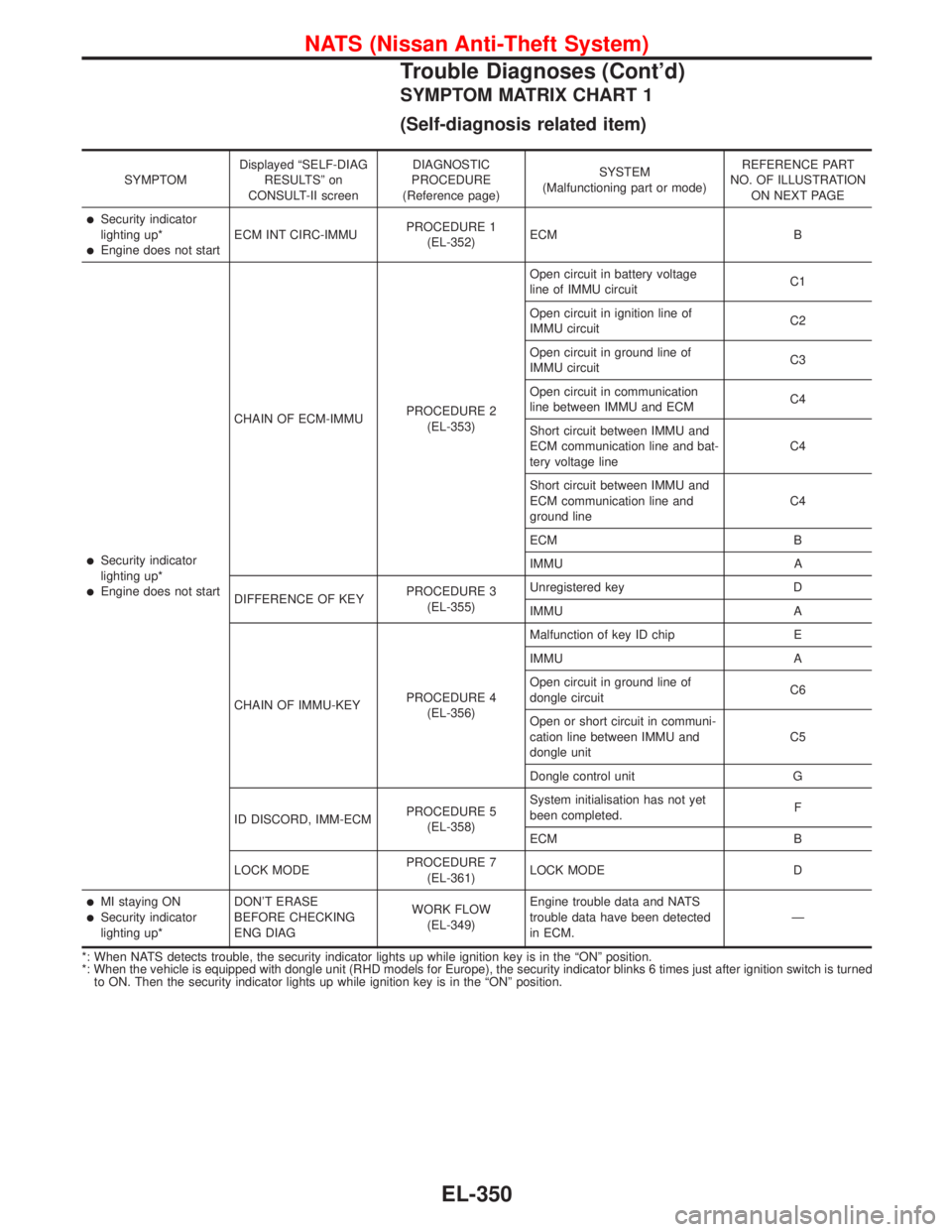
SYMPTOM MATRIX CHART 1
(Self-diagnosis related item)
SYMPTOMDisplayed“SELF-DIAG
RESULTS”on
CONSULT-II screenDIAGNOSTIC
PROCEDURE
(Reference page)SYSTEM
(Malfunctioning part or mode)REFERENCE PART
NO. OF ILLUSTRATION
ON NEXT PAGE
�Security indicator
lighting up*
�Engine does not startECM INT CIRC-IMMUPROCEDURE 1
(EL-352)ECM B
�Security indicator
lighting up*
�Engine does not startCHAIN OF ECM-IMMUPROCEDURE 2
(EL-353)Open circuit in battery voltage
line of IMMU circuitC1
Open circuit in ignition line of
IMMU circuitC2
Open circuit in ground line of
IMMU circuitC3
Open circuit in communication
line between IMMU and ECMC4
Short circuit between IMMU and
ECM communication line and bat-
tery voltage lineC4
Short circuit between IMMU and
ECM communication line and
ground lineC4
ECM B
IMMU A
DIFFERENCE OF KEYPROCEDURE 3
(EL-355)Unregistered key D
IMMU A
CHAIN OF IMMU-KEYPROCEDURE 4
(EL-356)Malfunction of key ID chip E
IMMU A
Open circuit in ground line of
dongle circuitC6
Open or short circuit in communi-
cation line between IMMU and
dongle unitC5
Dongle control unit G
ID DISCORD, IMM-ECMPROCEDURE 5
(EL-358)System initialisation has not yet
been completed.F
ECM B
LOCK MODEPROCEDURE 7
(EL-361)LOCK MODE D
�MI staying ON�Security indicator
lighting up*DON’T ERASE
BEFORE CHECKING
ENG DIAGWORK FLOW
(EL-349)Engine trouble data and NATS
trouble data have been detected
in ECM.—
*: When NATS detects trouble, the security indicator lights up while ignition key is in the“ON”position.
*: When the vehicle is equipped with dongle unit (RHD models for Europe), the security indicator blinks 6 times just after ignition switch is turned
to ON. Then the security indicator lights up while ignition key is in the“ON”position.
NATS (Nissan Anti-Theft System)
Trouble Diagnoses (Cont’d)
EL-350
Page 1483 of 2267

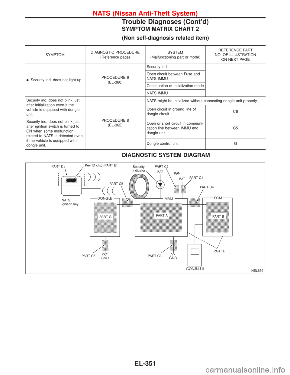
SYMPTOM MATRIX CHART 2
(Non self-diagnosis related item)
SYMPTOMDIAGNOSTIC PROCEDURE
(Reference page)SYSTEM
(Malfunctioning part or mode)REFERENCE PART
NO. OF ILLUSTRATION
ON NEXT PAGE
�Security ind. does not light up.PROCEDURE 6
(EL-360)Security ind.
Open circuit between Fuse and
NATS IMMU
Continuation of initialization mode
NATS IMMU
Security ind. does not blink just
after initialization even if the
vehicle is equipped with dongle
unit.
PROCEDURE 8
(EL-362)NATS might be initialized without connecting dongle unit properly.
Open circuit in ground line of
dongle circuitC6
Security ind. does not blink just
after ignition switch is turned to
ON when some malfunction
related to NATS is detected even
if the vehicle is equipped with
dongle unit.Open or short circuit in communi-
cation line between IMMU and
dongle unitC5
Dongle control unit G
DIAGNOSTIC SYSTEM DIAGRAM
NEL559 PA R T DKey ID chip (PART E)
NATS
ignition keyPA R T C 5Security
indicatorPA R T C 2
PA R T C 1
PA R T C 4
PA R T GPA R T A
PA R T B
PA R T C 6PA R T C 3PA R T F
NATS (Nissan Anti-Theft System)
Trouble Diagnoses (Cont’d)
EL-351
Page 1497 of 2267
Engine Compartment
YEL234C Front wiper motor (LHD models)
ABS actuator and electric unit
(Control unit)Relay boxFront wiper motor (RHD models)
Glow relay (CD engine models) Fusible link and fuse box
Cooling fan relay-1 Headlamp relay LH
Horn relay
Cooling fan relay-3
Accessory relayCooling fan relay-2 or power fuse
Air conditioner relay
Headlamp relay RH
Front wiper relayGlow relay
(CD engine models)
Rear wiper relayPark/Neutral position relay ECM relay
LOCATION OF ELECTRICAL UNITS
EL-365
Page 1498 of 2267
Passenger Compartment
LHD MODELS
YEL235C Time control unit
Blower
relay
Circuit
breaker-1Indicator control unit
Stop lamp switchNATS IMMU
Auto level control unit
Headlamp washer timer
Ignition
relay
Circuit breaker-2
Theft warning horn relay
Fuse block (J/B)
Rear window defogger relayAir bag diagnosis sensor unit
TCM (Transmission control module)Daytime light control unit
Fuse block (J/B)
Time control unt
Power window relay
Front fog lamp relay
Fuel pump relayA/C LOW relay, A/C MED-LOW relay, A/C MED-HIGH relay, A/C HIGH relayECM
LOCATION OF ELECTRICAL UNITS
EL-366
Page 1499 of 2267
RHD MODELS
YEL236C NATS IMMU
Auto level control unitHeadlamp washer timer
Stop lamp switch
A/C LOW relay. A/C MED-LOW relay. A/C MED-HIGH relay. A/C HIGH relayFuse block (J/B)
Power window relay Air bag diagnosis sensor unit
ECM
Front fog lamp relay TCM (Transmission control module)
Fuel pump relay Indicator control unit
Time control unit
Fuse block (J/B)
Time control unit
Ignition
relay
Circuit
breaker-1
Blower relay
Circuit breaker-2
Theft warning horn relay
Rear window defogger relay
LOCATION OF ELECTRICAL UNITS
Passenger Compartment (Cont’d)
EL-367
Page 1500 of 2267
OutlineLHD MODELS
RHD MODELS
YEL367B Rear door harness RH
(5-door Hatchback and Wagon)
Front door harness RHRoom lamp harness
Back door harness
Hatchback and Wagon
Rear door harness LH
(5-door Hatchback and Wagon)
Body harness
Front door harness LH Main harness
Engine room harness
Engine control harness
Sedan
Tail sub harnessTail harness
Rear door harness RH
Rear door har-
ness LH
Body harness Tail harness No. 2
Console harness Air conditioner harnessConsole harness
YEL237C Rear door harness RH
(5-door Hatchback and Wagon)
Main harnessFront door
harness RHRoom lamp harness
Back door harness
Hatchback and Wagon
Rear door harness LH
(5-door Hatchback and Wagon)
Body harness
Front door harness LH
Engine room harness
Engine control harness
Sedan
Tail harness
Rear door harness RH
Rear door
harness LH
Body harness Tail sub harness
Tail harness No. 2
Console harness
Air conditioner harness
Console harness
HARNESS LAYOUT
EL-368
Page 1502 of 2267
Engine Control Harness
QG ENGINE
YEL957C
HARNESS LAYOUT
EL-370