Page 1460 of 2267
 can be
switched into Diagnostic Mode (see page EL-309 ho")
Trouble Diagnoses
Alarm Trigger Feedback
To verify the last three triggers that activated the theft warning system, the Time Control Unit (TCU) can be
switched into Diagnostic Mode (see page EL-309 how to enter Diagnostic Mode).
Approximately 2 seconds after the TCU has finished flashing the hazard lamp to confirm that the Diagnos-
tic Mode has been successfully entered, the TCU will generate a short beep indicating the trigger that will
be displayed. A single beep means the most recent trigger, three beeps means the oldest trigger. Following
each beep or group of beeps, the hazard lamp will flash to indicate the alarm trigger.
Source of Alarm Trigger Number (of flashes)
Driver’s door lock status switch 1
Passenger door lock status switch 2
Rear door lock status switch 3
Ignition line 4
Driver’s door open switch 5
Other door open switch 6
Trunk or back door open switch 8
Hood switch 9
Ultra sonic sensors 10
Smash sensor (Wagon vehicles) 11
In case there have been no alarm triggers, there will be no indicator flashes between the audible signals.
After completing the alarm trigger feedback, the TCU will enter Diagnostic Mode as described on page
EL-309.
Before continuing trouble diagnoses on the next page, perform the checks as mentioned in the table on page
EL-310.
THEFT WARNING SYSTEM
EL-328
Page 1461 of 2267

PRELIMINARY CHECK
The system operation is canceled by turning the ignition switch to“ON”at any step between START and
ARMED in the following flow chart.
System phase
START
Note: Before starting operation check, open front windows.
�DISARMED
Turn ignition switch“OFF”and remove the ignition key.
“SECURITY”indicator lamp will blink every 2.6 seconds.
(NATS)
OK
�NG
Refer to
NATS trouble
diagnosis.
Close all doors, hood and trunk lid.
Press the ultrasonic cancel switch. The“SECURITY”indicator
lamp will go on for approximately 6 seconds.
OK
�NG
SYMPTOM 1
PRE-ARMED
Lock doors using key or multi-remote controller.
ARMED
For about 30 seconds,“SECURITY”indicator lamp will blink
intermittently.
OK
�NG
SYMPTOM 2
Disarm the system by unlocking the vehicle using the remote
controller. Arm the system again without excluding the ultra-
sonic sensors.
ALARM
Unlock any door without multi-remote controller, activate the
ultra sonic sensors by inserting an object into the vehicle’s
interior, or open hood or trunk.
.......................................................................................................
Alarm (horn and hazard lamp) will operate.
OK
�NG
SYMPTOM 3
�NG
SYMPTOM 4
�DISARMED
Unlock the vehicle using the multi-remote controller or insert
the key in the ignition and switch it to ON.
Alarm (horn and hazard lamp) will stop.
OK
�NG
SYMPTOM 5
System is OK.
After performing preliminary check, go to symptom chart on next page.
�
�
�
��
��
�
��
��
�
THEFT WARNING SYSTEM
Trouble Diagnoses (Cont’d)
EL-329
Page 1462 of 2267

Before starting trouble diagnoses below, perform preliminary check, EL-329.
Symptom numbers in the symptom chart correspond with those of Preliminary check.
SYMPTOM CHART
Procedure—Power supply
and ground
circuit checkDiagnostic procedure——
REFERENCE PAGE
EL-329
EL-331
EL-331
EL-332
EL-336
EL-337
EL-338
EL-339
EL-340
EL-341
EL-296
EL-342
SYMPTOMPreliminary check
Power supply circuit check
Ground circuit check
Diagnostic Procedure 1
(Door, hood and trunk room lamp switch check)
Diagnostic Procedure 2
(Security indicator lamp check)
Diagnostic Procedure 3
(Door unlock sensor check)
Diagnostic Procedure 4
(Door key cylinder switch check)
Diagnostic Procedures 5
(Smash sensor check)
Diagnostic Procedure 6
(Theft warning horn alarm check)
Diagnostic procedure 7
(Hazard lamp alarm check)
Check“MULTI-REMOTE
CONTROL”system.
Check“NATS (Nissan Anti-Theft system)”.
1Security indicator does not turn“ON”
or blinking.XXX X
2
Theft warning
system cannot
be set by...
Allitems XXXX X
Door out side key X X X X
Multi-remote control X X X X
3
*1 Theft warning
system does not
alarm when...
Any door is opened.XXXX
Any door is unlocked with-
out using key or multi-re-
mote controllerXXX X
Glass breakage is deteted
(Wagon)XXX X
4
Theft warning
alarm does not
activate.
All functionXXXX X
Horn alarm X X X X
Hazard lamp X X X X
5
Theft warning
system cannot be
canceled by...
Turning the ignition ON *2 X X X X
Multi-remote controller X X X X
X: Applicable
*1: Make sure the system is in the armed phase.
*2: Make sure the key is NATS registered.
THEFT WARNING SYSTEM
Trouble Diagnoses (Cont’d)
EL-330
Page 1463 of 2267
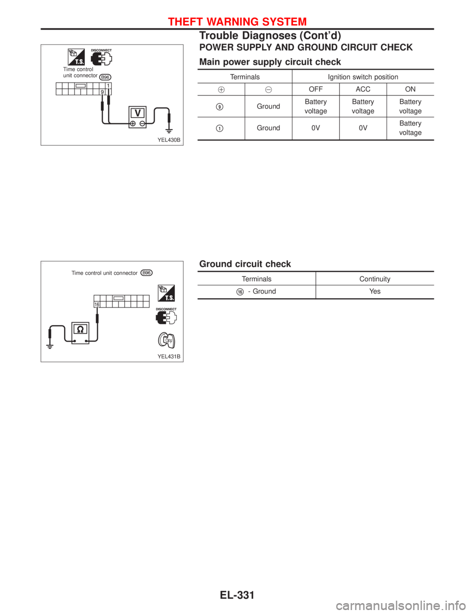
POWER SUPPLY AND GROUND CIRCUIT CHECK
Main power supply circuit check
Terminals Ignition switch position
��OFF ACC ON
�9GroundBattery
voltageBattery
voltageBattery
voltage
�1Ground 0V 0VBattery
voltage
Ground circuit check
Terminals Continuity
�16- Ground Yes
YEL430B Time control
unit connector
YEL431B Time control unit connector
THEFT WARNING SYSTEM
Trouble Diagnoses (Cont’d)
EL-331
Page 1464 of 2267

—With driver door switch type-1—
(Door switch check)
CHECK DOOR SWITCH INPUT SIG-
NAL.
Remove time control unit from fuse
block.
Note: Fuse block (J/B) is very frag-
ile")
DIAGNOSTIC PROCEDURE 1-(1)
—With driver door switch type-1—
(Door switch check)
CHECK DOOR SWITCH INPUT SIG-
NAL.
Remove time control unit from fuse
block.
Note: Fuse block (J/B) is very frag-
ile. TCU should be removed care-
fully to avoid breaking the locking
bars.
Check continuity between fuse block
(J/B) and ground.
NG
�OK
Door switch is OK.
CHECK GROUND CIRCUIT.
1) Disconnect driver side door switch
connector.
2) Check harness continuity between
terminal
�2and ground.
Continuity should exist.
OK
�NG
Repair harness or con-
nector.
CHECK DOOR SWITCH.
1) Disconnect door switch connector.
2) Check continuity between door
switch terminals.
OK
�NG
Replace door switch.
Check the following.
�Door switch ground condition
(Except driver side)
�Harness for open or short between
control unit and door switch
Termi-
nalsCondition Continuity
Driver
side door
16JOpened Yes
Closed No
Other
door
7JOpened Yes
Closed No
Terminals ConditionContinu-
ity
Driver
side door
switch
�2-�3Closed No
Open Yes
Other
door
switches
�1-
groundClosed No
Open Yes
YEL829
Fuse block (J/B) connector
YEL831
Door switch connector
Driver side:
YEL830
Door switch connector
Driver side:
Door switch connector
Passenger side:
Rear side:
�
�
�
THEFT WARNING SYSTEM
Trouble Diagnoses (Cont’d)
EL-332
Page 1465 of 2267
DIAGNOSTIC PROCEDURE 1-(1)
—With driver door switch type-2—
(Door switch check)
CHECK DOOR SWITCH INPUT SIG-
NAL.
Remove time control unit from fuse
block.
Note: Fuse block (J/B) is very frag-
ile. TCU should be removed care-
fully to avoid breaking the locking
bars.
Check continuity between fuse block
(J/B) and ground.
NG
�OK
Door switch is OK.
CHECK DOOR SWITCH.
1) Disconnect door switch connector.
2) Check continuity between door
switch terminals.
OK
�NG
Replace door switch.
Check the following.
�Door switch ground condition
�Harness for open or short between
control unit and door switch
Termi-
nalsCondition Continuity
Driver
side door
16JOpened Yes
Closed No
Other
door
7JOpened Yes
Closed No
Terminals Condition Continuity
�1- groundClosed No
Open Yes
YEL829
Fuse block (J/B) connector
YEL033D
�
�
THEFT WARNING SYSTEM
Trouble Diagnoses (Cont’d)
EL-333
Page 1466 of 2267
DIAGNOSTIC PROCEDURE 1-(2)
(Hood switch check)
CHECK HOOD SWITCH INPUT SIG-
NAL.
Remove time control unit from fuse
block.
Note: Fuse block (J/B) is very frag-
ile. TCU should be removed care-
fully to avoid breaking the locking
bars.
Check continuity between control unit
terminal
�32and ground.
Refer to wiring diagram in EL-317.
OK
�OK
Hood switch is OK.
CHECK HOOD SWITCH.
1. Disconnect hood switch connector.
2. Check continuity between hood
switch terminals.
OK
�NG
Replace hood switch.
Check the following.
�Hood switch ground circuit
�Harness for open or short between
control unit and hood switch
Condition Continuity
Hood is open. Yes
Hood is closed. No
Terminals Condition Continuity
�1-�2Pushed No
Released Yes
YEL457B Time control
unit connector
YEL458B Hood switch connector�
�
THEFT WARNING SYSTEM
Trouble Diagnoses (Cont’d)
EL-334
Page 1467 of 2267

(Trunk room or luggage room lamp switch check)
CHECK TRUNK ROOM OR LUG-
GAGE ROOM LAMP SWITCH INPUT
SIGNAL.
Remove time control unit from fuse
block.
Note: Fuse block (J/B)")
DIAGNOSTIC PROCEDURE 1-(3)
(Trunk room or luggage room lamp switch check)
CHECK TRUNK ROOM OR LUG-
GAGE ROOM LAMP SWITCH INPUT
SIGNAL.
Remove time control unit from fuse
block.
Note: Fuse block (J/B) is very frag-
ile. TCU should be removed care-
fully to avoid breaking the locking
bars.
Check continuity between control unit
terminal
�33and ground.
Refer to wiring diagram in EL-319.
NG
�OK
Trunk room or luggage
room lamp switch is OK.
CHECK TRUNK ROOM OR LUG-
GAGE ROOM LAMP SWITCH.
1. Disconnect trunk room or luggage
room lamp switch connector.
2. Check continuity between trunk
room lamp switch terminals.
OK
�NG
Replace trunk room or
luggage room lamp
switch.
Check the following.
�Trunk room or luggage room lamp
switch ground circuit
�Harness for open or short between
control unit and trunk room or lug-
gage room lamp switch
Condition Continuity
Trunk lid or back
door is open.Ye s
Trunk lid or back
door is closed.No
Terminals Condition Continuity
�1-�2Closed No
Open Yes
YEL459B Time control
unit connector
YEL460B Trunk room lamp switch connector
Luggage room lamp switch
Luggage room lamp switch
�
�
THEFT WARNING SYSTEM
Trouble Diagnoses (Cont’d)
EL-335

—With driver door switch type-2—
(Door switch check)
CHECK DOOR SWITCH INPUT SIG-
NAL.
Remove time control unit from fuse
block.
Note: Fuse block (J/B) is very frag-
ile")

(Hood switch check)
CHECK HOOD SWITCH INPUT SIG-
NAL.
Remove time control unit from fuse
block.
Note: Fuse block (J/B) is very frag-
ile. TCU should be removed care-
fully t")