Page 1468 of 2267

CHECK INDICATOR LAMP OUTPUT
SIGNAL.
1) Remove time control unit from fuse
block.
Note: Fuse block (J/B) is very
fragile. TCU should be removed
careful")
DIAGNOSTIC PROCEDURE 2
(Security indicator check)
CHECK INDICATOR LAMP OUTPUT
SIGNAL.
1) Remove time control unit from fuse
block.
Note: Fuse block (J/B) is very
fragile. TCU should be removed
carefully to avoid breaking the
locking bars.
2) Check voltage between control unit
terminal
�18and ground.
Battery voltage should exist.
Refer to wiring diagram EL-316.
NG
�OK
Security indicator lamp is
OK.
Security
indicator on
dashboardSecurity indica-
tor built-in com-
bination meter��A
CHECK INDICATOR LAMP.
OK
�NG
Replace indicator lamp.
CHECK POWER SUPPLY CIRCUIT
FOR INDICATOR.
1) Disconnect security indicator con-
nector.
2) Check voltage between indicator
terminal
�2and ground.
Battery voltage should exist.
OK
�NG
Check the following:
�10A fuse [No.16 ,
located in the fuse
block (J/B)]
�Harness for open or
short between security
indicator lamp and
fuse
Check harness for open or short
between security indicator and control
unit.
�A
CHECK INDICATOR LAMP.
OK
�NG
Replace combination
meter.
CHECK POWER SUPPLY CIRCUIT
FOR INDICATOR.
1) Disconnect combination meter con-
nector.
2) Check voltage between indicator
terminal
�23and ground.
Battery voltage should exist.
OK
�NG
Check the following:
�10A fuse [No.16 ,
located in the fuse
block (J/B)]
�Harness for open or
short between combi-
nation meter and fuse
Check harness for open or short
between combination meter and con-
trol unit.
YEL461B Time control
unit connector
YEL462B Security indicator
connector
YEL037D
�
�
�
�
�
�
THEFT WARNING SYSTEM
Trouble Diagnoses (Cont’d)
EL-336
Page 1469 of 2267

CHECK DOOR UNLOCK SENSOR INPUT
SIGNAL.
Remove time control unit from fuse block.
Note: Fuse block (J/B) is very fragile.
TCU should be removed careful")
DIAGNOSTIC PROCEDURE 3
(Door unlock sensor check)
CHECK DOOR UNLOCK SENSOR INPUT
SIGNAL.
Remove time control unit from fuse block.
Note: Fuse block (J/B) is very fragile.
TCU should be removed carefully to
avoid breaking the locking bars.
Check continuity between control unit termi-
nals
�25,�35,�36and ground.
Refer to wiring diagram in EL-327.
NG
�OK
Door unlock sensor
is OK.
CHECK DOOR UNLOCK SENSOR.
1. Disconnect door unlock sensor connec-
tor.
2. Check continuity between door unlock
sensor terminals.
OK
�NG
Replace door
unlock sensor.
Check the following:
�Door unlock sensor ground circuit
�Harness for open or short between con-
trol unit and door unlock sensor
Terminals
Condition Continuity
��
Driver
side door
�35GroundLocked No
Unlocked Yes
Passen-
ger
side door
�36GroundLocked No
Unlocked Yes
Rear
door
�25GroundLocked No
Unlocked Yes
Terminals Condition Continuity
�2-�5Locked No
Unlocked Yes
YEL463B
Time control
unit connector
YEL038D
�
�
THEFT WARNING SYSTEM
Trouble Diagnoses (Cont’d)
EL-337
Page 1470 of 2267

CHECK DOOR KEY CYLINDER
SWITCH INPUT SIGNAL (LOCK SIG-
NAL).
Remove time control unit from fuse
block.
Note: Fuse block (J/B) is very fragile.
T")
DIAGNOSTIC PROCEDURE 4
(Door key cylinder switch check)
CHECK DOOR KEY CYLINDER
SWITCH INPUT SIGNAL (LOCK SIG-
NAL).
Remove time control unit from fuse
block.
Note: Fuse block (J/B) is very fragile.
TCU should be removed carefully to
avoid breaking the locking bars.
Check continuity between time control
unit connector terminal
�29and
ground.
NG
�OK
Door key cylinder switch
is OK.
CHECK DOOR KEY CYLINDER
SWITCH.
1) Disconnect door key cylinder switch
connector.
2) Check continuity between door key
cylinder switch terminals.
OK
�NG
Replace key cylinder
switch.
Check the following:
�Harness connectorsB3,M13
�Harness connectorsM7,D1
�Harness connectorsB5,D2
�Harness connectorsB56,D11
�Door key cylinder switch ground cir-
cuit
�Harness for open or short-circuit
between super lock control unit and
door key cylinder.
Key cylinder switch operation Continuity
Between neutral and lock Yes
Unlock/neutral No
Terminals Key position Continuity
�1-�2
Neutral No
Between
neutral and
lockYe s
Unlock/
neutralNo
Full stroke
(Lock)No
YEL447B
Time control unit connector
Continuity exists
LockNeutral
Unlock
LH side
Neutral
UnlockContinuity exists
Lock
RH side
YEL817
Key cylinder switch
Driver side :
Passenger side:
�
�
THEFT WARNING SYSTEM
Trouble Diagnoses (Cont’d)
EL-338
Page 1471 of 2267
DIAGNOSTIC PROCEDURE 5
(Smash sensor check)
1. Remove time control unit from fuse
block.
Note: Fuse block (J/B) is very
fragile. TCU should be removed
carefully to avoid breaking the
locking bars.
2. Check harness continuity between
control unit terminal
�31and ground.
Continuity should exist.
OK
�NG
Check the following.
�Smash sensor circuit
for open.
�Harness for open
between control unit,
smash sensors and
ground.
1. Disconnect rear window smash sen-
sor connector.
2. Check harness continuity between
control unit and ground.
Continuity should not exist.
NG
�OK
Smash sensor is OK.
Check harness for short between con-
trol unit and ground.
YEL457B Time control
unit connector
NEL546 Time control unit connector
�
�
THEFT WARNING SYSTEM
Trouble Diagnoses (Cont’d)
EL-339
Page 1472 of 2267

CHECK THEFT WARNING HORN
ALARM OPERATION.
1. Remove time control unit from fuse
block.
Note: Fuse block (J/B) is very
fragile. TCU should be rem")
DIAGNOSTIC PROCEDURE 6
(Theft warning horn alarm check)
CHECK THEFT WARNING HORN
ALARM OPERATION.
1. Remove time control unit from fuse
block.
Note: Fuse block (J/B) is very
fragile. TCU should be removed
carefully to avoid breaking the
locking bars.
2. Apply ground to control unit connec-
tor terminal
�43.
Does horn alarm activate?
Refer to wiring diagram EL-319.
No
�Ye s
Horn alarm is OK.
Check theft warning horn relay.
OK
�NG
Replace.
CHECK POWER SUPPLY FOR THEFT
WARNING HORN RELAY.
1) Disconnect theft warning horn relay
connector.
2) Check voltage between terminal
�2
and ground, and�3and ground.
Battery voltage should exist.
OK
�NG
Check the following:
�10A fuse (No.16 ,
located in the fuse and
fusible link box)
�Harness for open or
short between theft
warning horn relay and
fuse
CHECK THEFT WARNING HORN
RELAY CIRCUIT.
1. Disconnect theft warning horn relay
connector.
2. Check continuity between theft
warning horn relay
�1and control
unit terminal
�43.
Continuity should exist.
3. Check continuity between theft
warning horn relay
�5and theft
warning horn connector terminal
�1.
Continuity should exist.
OK
�NG
Repair harness.
Check harness for open or short
between theft warning horn relay and
control unit.
YEL465B
Time control unit connector
YEL466B
Theft warning horn
relay connector
YEL467B
Theft warning horn
relay connector
�
�
�
�
THEFT WARNING SYSTEM
Trouble Diagnoses (Cont’d)
EL-340
Page 1473 of 2267
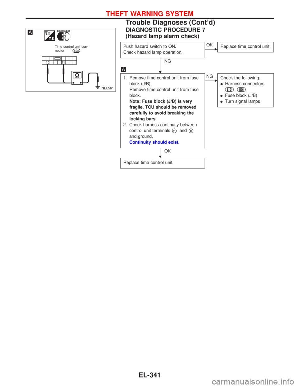
DIAGNOSTIC PROCEDURE 7
(Hazard lamp alarm check)
Push hazard switch to ON.
Check hazard lamp operation.
NG
�OK
Replace time control unit.
1. Remove time control unit from fuse
block (J/B).
Remove time control unit from fuse
block.
Note: Fuse block (J/B) is very
fragile. TCU should be removed
carefully to avoid breaking the
locking bars.
2. Check harness continuity between
control unit terminals
�11and�15
and ground.
Continuity should exist.
OK
�NG
Check the following.
�Harness connectors
E104,B96
�Fuse block (J/B)
�Turn signal lamps
Replace time control unit.
NEL561 Time control unit con-
nector
�
�
THEFT WARNING SYSTEM
Trouble Diagnoses (Cont’d)
EL-341
Page 1475 of 2267
Wiring Diagram—NATS—
MODELS BEFORE VIN - P11U0548750 (Type-1)
YEL216C
BATTERY BATTERYIGNITION SWITCH
ON or START
FUSE
BLOCK
(J/B)Refer to EL-POWER.
NATS
SECURITY
INDICATORAUDIODONGLE
CONTROL UNIT: With gasoline engine
: With diesel engine
: With GA engine
: With SR engine or
QG engine
: RHD models
: Except
INJECTION
PUMPTIME
CONTROL
UNIT
REFER TO THE FOLLOWING
FUSE BLOCK - Junction Box (J/B)
FUSE BLOCK - Junction Box (J/B)
FUSE BLOCK - Junction Box (J/B)
FUSE BLOCK - Junction Box (J/B)
FUSE BLOCK - Junction Box (J/B)
NATS (Nissan Anti-Theft System)
EL-343
Page 1478 of 2267
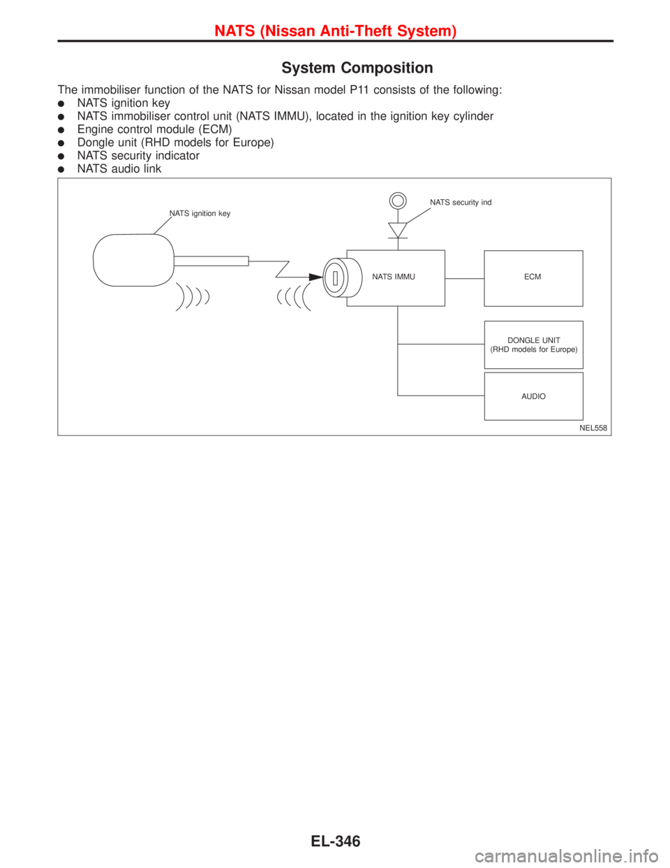
System Composition
The immobiliser function of the NATS for Nissan model P11 consists of the following:
�NATS ignition key
�NATS immobiliser control unit (NATS IMMU), located in the ignition key cylinder
�Engine control module (ECM)
�Dongle unit (RHD models for Europe)
�NATS security indicator
�NATS audio link
NEL558 NATS ignition key
NATS IMMUNATS security ind
ECM
DONGLE UNIT
(RHD models for Europe)
AUDIO
NATS (Nissan Anti-Theft System)
EL-346

1. Remove time control unit from fuse
block.
Note: Fuse block (J/B) is very
fragile. TCU should be removed
carefully to avoid breaking the
locking bars.
2.")

YEL216C
BATTERY BATTERYIGNITION SWITCH
ON or START
FUSE
BLOCK
(J/B)Refer to EL-POWER.
NATS
SECURITY
INDICATORAUDIODONGLE
CONTROL UNIT:")