Page 1590 of 2267

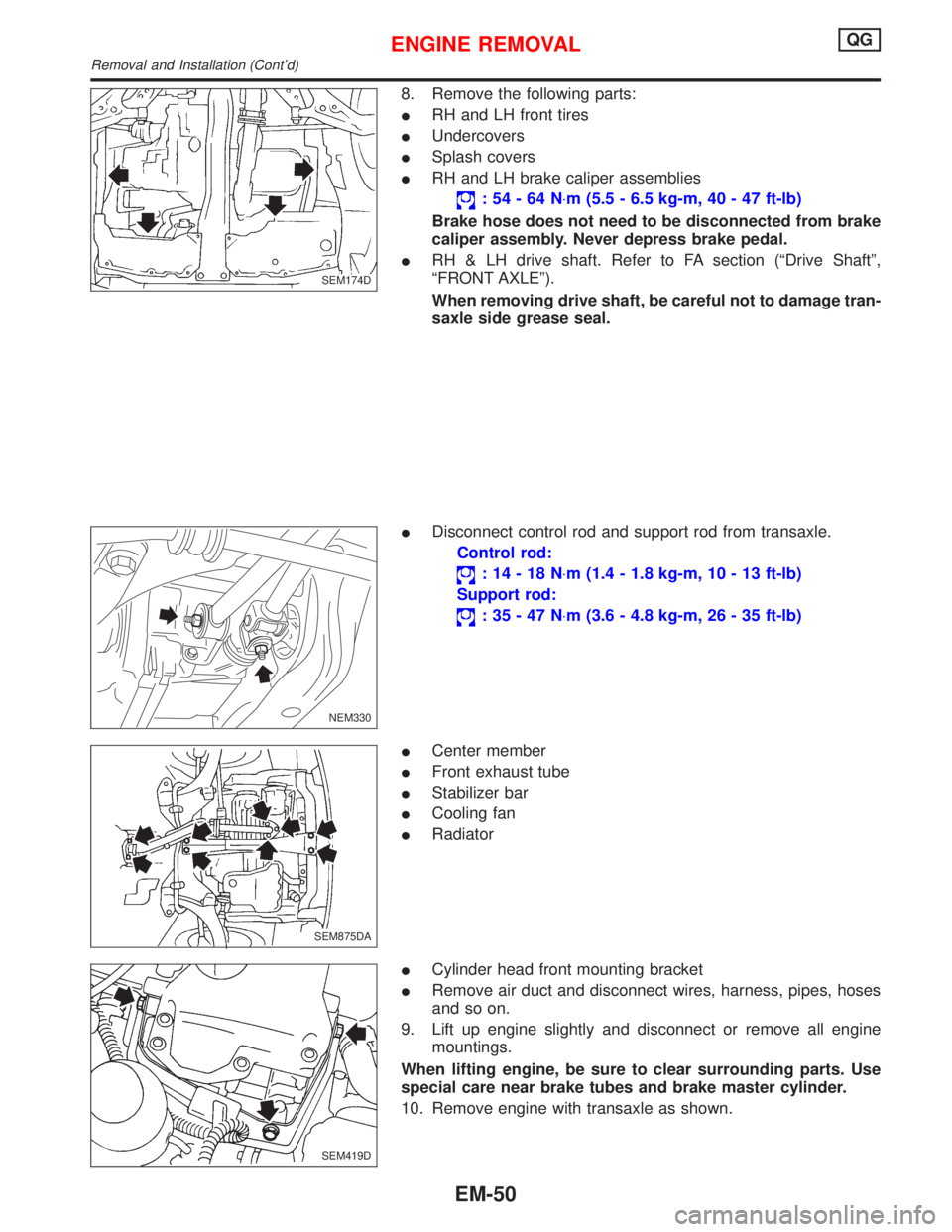
8. Remove the following parts:
IRH and LH front tires
IUndercovers
ISplash covers
IRH and LH brake caliper assemblies
:54-64N×m (5.5 - 6.5 kg-m, 40 - 47 ft-lb)
Brake hose does not need to be disconnected from brake
caliper assembly. Never depress brake pedal.
IRH & LH drive shaft. Refer to FA section (ªDrive Shaftº,
ªFRONT AXLEº).
When removing drive shaft, be careful not to damage tran-
saxle side grease seal.
IDisconnect control rod and support rod from transaxle.
Control rod:
:14-18N×m (1.4 - 1.8 kg-m, 10 - 13 ft-lb)
Support rod:
:35-47N×m (3.6 - 4.8 kg-m, 26 - 35 ft-lb)
ICenter member
IFront exhaust tube
IStabilizer bar
ICooling fan
IRadiator
ICylinder head front mounting bracket
IRemove air duct and disconnect wires, harness, pipes, hoses
and so on.
9. Lift up engine slightly and disconnect or remove all engine
mountings.
When lifting engine, be sure to clear surrounding parts. Use
special care near brake tubes and brake master cylinder.
10. Remove engine with transaxle as shown.
SEM174D
NEM330
.SEM875DA
SEM419D
ENGINE REMOVALQG
Removal and Installation (Cont'd)
EM-50
Page 1607 of 2267
p1Injector
p2Pressure regulator
p3IACV-AAC valve
p4Canister purge control valve
p5Injector tube
p6Throttle body
p7Throttle position sensor
p8Intake manifold
NEM337
.
SEC. 140×147×163×164
6.9 - 9.5
(0.70 - 0.97,
60.8 - 84.2)
6.9 - 9.5
(0.70 - 0.97, 60.8 - 84.2)
2.9 - 3.8 (0.30 - 0.39, 26.0 - 33.9)
O-ring
1st 9 - 11 (1.0 - 1.1,
7.0 - 8.0)
2nd 21 - 26 (2.2 - 2.6,
16.0 - 19.0)
I
Gasket
6.9 - 9.5
(0.70 - 0.97,
60.8 - 84.2)6.9 - 9.5
(0.70 - 0.97, 60.8 - 84.2)O-ring
Clip
Gasket
2.0 - 2.5
(0.20 - 0.26,
17.4 - 22.6)Gasket
3.0 - 4.0 (0.31 - 0.41, 26.9 - 35.6)
18 - 21 (1.9 - 2.2, 13.3 - 15.4)Gasket
18-21
(1.9 - 2.2,
13.3 - 15.4)
: N´m (kg-m, ft-lb)
: N´m (kg-m, in-lb)
î : Do not re-use IThrottle body bolts tightening procedure
1) Tighten all bolts to 9 to 11 N´m (0.9 - 1.1 kg-m, 6.5 - 8.0 ft-lb)
2) Tighten all bolts to 18 to 22 N´m (1.8 - 2.2 kg-m, 13 - 16 ft-lb)
Tighten in
numerical order.
OUTER COMPONENT PARTSSR20DE
EM-67
Page 1664 of 2267

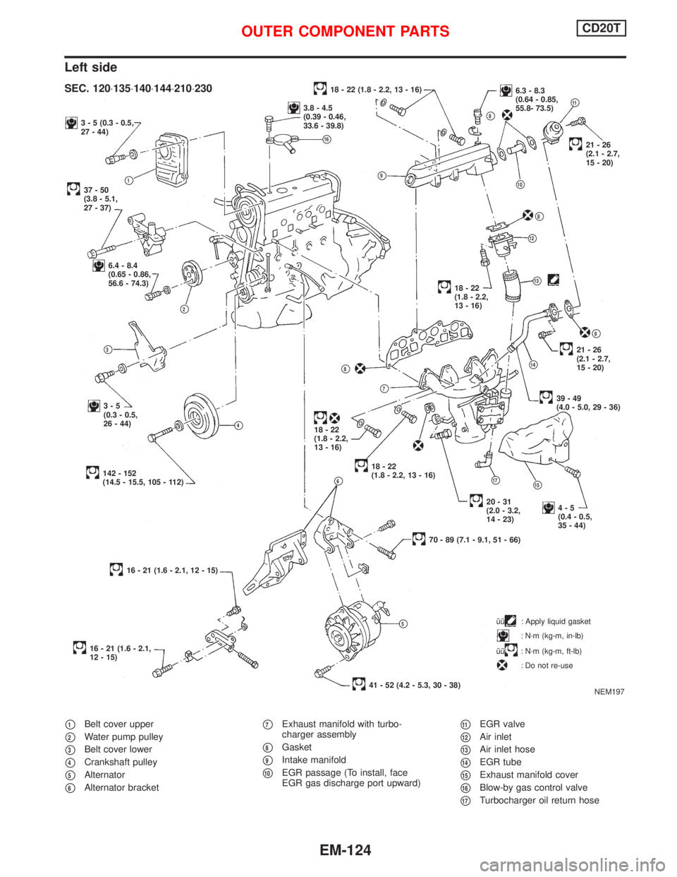
Left side
p1Belt cover upper
p2Water pump pulley
p3Belt cover lower
p4Crankshaft pulley
p5Alternator
p6Alternator bracket
p7Exhaust manifold with turbo-
charger assembly
p8Gasket
p9Intake manifold
p10EGR passage (To install, face
EGR gas discharge port upward)
p11EGR valve
p12Air inlet
p13Air inlet hose
p14EGR tube
p15Exhaust manifold cover
p16Blow-by gas control valve
p17Turbocharger oil return hose
3 - 5 (0.3 - 0.5,
27 - 44)
37-50
(3.8 - 5.1,
27 - 37)p1
6.4 - 8.4
(0.65 - 0.86,
56.6 - 74.3)
p2
p9
p3
3-5
(0.3 - 0.5,
26 - 44)
p4
142 - 152
(14.5 - 15.5, 105 - 112)p6
16 - 21 (1.6 - 2.1, 12 - 15)
16 - 21 (1.6 - 2.1,
12 - 15)îî
: Apply liquid gasket
: N´m (kg-m, in-lb)
îî
: N´m (kg-m, ft-lb)
: Do not re-use
18 - 22 (1.8 - 2.2, 13 - 16)6.3 - 8.3
(0.64 - 0.85,
55.8- 73.5)
p11
p8
p10
.21-26
(2.1 - 2.7,
15 - 20)
p8
p12
p1318-22
(1.8 - 2.2,
13 - 16)
p8
21-26
(2.1 - 2.7,
15 - 20)
p14
39-49
(4.0 - 5.0, 29 - 36)
p8
p7
18-22
(1.8 - 2.2,
13 - 16)
.18-22
(1.8 - 2.2, 13 - 16)
p17p15
4-5
(0.4 - 0.5,
35 - 44)
70 - 89 (7.1 - 9.1, 51 - 66)
p5
41 - 52 (4.2 - 5.3, 30 - 38)
NEM197
SEC. 120×135×140×144×210×230
3.8 - 4.5
(0.39 - 0.46,
33.6 - 39.8)
p16
20-31
(2.0 - 3.2,
14 - 23)
OUTER COMPONENT PARTSCD20T
EM-124
Page 1718 of 2267
General SpecificationsNCEM0028
EngineQG16DE QG18DE
ClassificationGasoline
Cylinder arrangement4, in-line
Displacement
cm
3(cu in)1,596 (97.39) 1,769 (107.94)
Bore´stroke
mm (in)76.0´88.0 (2.992´3.465) 80.0´88.0 (3.150´3.465)
Valve arrangementDOHC
Firing order1-3-4-2
Number of piston ringsCompression 2
Oil 1
Number of main bearings5
Compression ratio9.5
EM120
abcde f
Valve timingQG16DE 222É 228É -4É (16É) 52É (32É) þ2É 44É
QG18DE 222É 236É 0É (20É) 56É (36É) þ2É 44É
( ): Valve timing control ON
Compression PressureNJEM0029Unit: kPa (bar, kg/cm2, psi)/350 rpm
Standard1,324 (13.24, 13.5, 192)
Minimum1,128 (11.28, 11.5, 164)
Difference limit between cylinders 98 (0.98, 1.0, 14)
Cylinder HeadNCEM0030Unit: mm (in)
Standard Limit
Head surface flatness Less than 0.03 (0.0012) 0.1 (0.004)
Height 117.8 - 118.0 (4.638 - 4.646) Ð
SERVICE DATA AND SPECIFICATIONS (SDS)QG
General Specifications
EM-178
Page 1779 of 2267
ACCELERATOR CONTROL, FUEL &
EXHAUST SYSTEMS
SECTION
FE
CONTENTS
PREPARATION.............................................................. 2
Special Service Tool .................................................. 2
QG16DE, QG18DE, SR20DE
ACCELERATOR CONTROL SYSTEM......................... 3
Adjusting Accelerator Cable ...................................... 4
CD20T
ACCELERATOR CONTROL SYSTEM......................... 5
QG16DE, QG18DE, SR20De, CD20T
FUEL SYSTEM.............................................................. 6
Fuel Pump and Gauge .............................................. 7
EXHAUST SYSTEM...................................................... 9
FE
Page 1781 of 2267
CAUTION:
lWhen removing accelerator cable, mark location to indicate lock nut's initial position.
lCheck that throttle valve is completely open when accelerator pedal is fully depressed. Check
that throttle valve returns to idle position when accelerator pedal is released.
lCheck accelerator control does not interfere with any adjacent parts.
lWhen connecting accelerator cable, be careful not to twist or scratch cable.
p1Accelerator cable
p2Cable bracketp3Pedal bracket
p4Return springp5Accelerator pedal
NFE062
SEC. 180
p1p2(LHD models)
p1
3 - 4 (0.3 - 0.4, 27 - 35)
3 - 4 (0.3 - 0.4, 27 - 35)
p2(RHD models)
p5
p4
3 - 4 (0.3 - 0.4, 27 - 35)
p3
: N´m (kg-m, in-lb)
ACCELERATOR
CONTROL SYSTEMQG16DE, QG18DE, SR20DE
FE-3
Page 1782 of 2267
Adjusting Accelerator Cable
1. Loosen lock nut, and tighten adjusting nut until throttle drum
starts to move.
2. From that position turn back adjusting nut 1.5 to 2 turns, and
secure lock nut.
NFE020 Throttle drum
Accelerator
Adjusting nut Lock nut
8-11N´m
(0.8 - 1.1 kg-m,
71 - 97 in-lb)
ACCELERATOR
CONTROL SYSTEMQG16DE, QG18DE, SR20DE
FE-4
Page 1783 of 2267
p1Pedal bracket
p2Accelerator position sensorp3Accelerator cable
p4Return springp5Accelerator pedal
lIf MIL illuminates after engine has started, refer to ªON
BOARD DIAGNOSTIC SYSTEM DESCRIPTIONº in EC
section for instructions.
NFE043
p1
p5
6 - 7 (0.61 - 0.71, 53.1 - 62.0)
p4
p3
p2
2.9 - 3.9 (0.30 - 0.40, 25.7 - 34.5)
SEC. 180
: Apply grease
: N´m (kg-m, in-lb)
: Do not re-use
2.9 - 3.9 (0.3 - 0.4, 25.7 - 34.5)
ACCELERATOR CONTROL SYSTEMCD20T
FE-5