Page 1923 of 2267

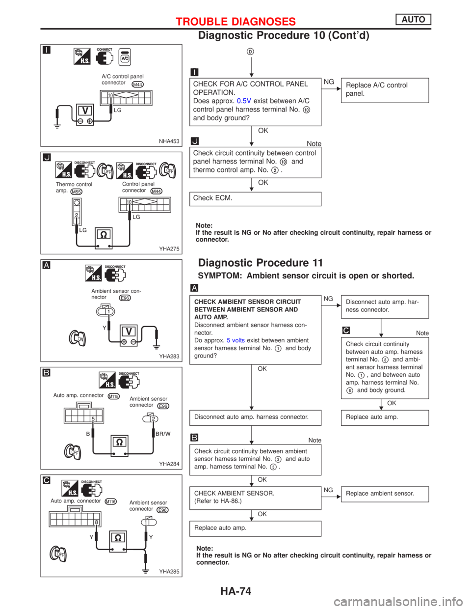
pD
CHECK FOR A/C CONTROL PANEL
OPERATION.
Does approx.0.5Vexist between A/C
control panel harness terminal No.
p10
and body ground?
OK
ENG
Replace A/C control
panel.
Note
Check circuit continuity between control
panel harness terminal No.
p10and
thermo control amp. No.
p2.
OK
Check ECM.
Note:
If the result is NG or No after checking circuit continuity, repair harness or
connector.
Diagnostic Procedure 11
SYMPTOM: Ambient sensor circuit is open or shorted.
CHECK AMBIENT SENSOR CIRCUIT
BETWEEN AMBIENT SENSOR AND
AUTO AMP.
Disconnect ambient sensor harness con-
nector.
Do approx.5 voltsexist between ambient
sensor harness terminal No.
p1and body
ground?
OK
ENG
Disconnect auto amp. har-
ness connector.
Note
Check circuit continuity
between auto amp. harness
terminal No.
p8and ambi-
ent sensor harness terminal
No.
p1, and between auto
amp. harness terminal No.
p8and body ground.
OK
Disconnect auto amp. harness connector.
Replace auto amp.
Note
Check circuit continuity between ambient
sensor harness terminal No.
p2and auto
amp. harness terminal No.
p5.
OK
CHECK AMBIENT SENSOR.
(Refer to HA-86.)
OK
ENG
Replace ambient sensor.
Replace auto amp.
Note:
If the result is NG or No after checking circuit continuity, repair harness or
connector.
NHA453
A/C control panel
connector
YHA275
Thermo control
amp.Control panel
connector
YHA283
Ambient sensor con-
nector
YHA284
Auto amp. connector
Ambient sensor
connector
YHA285
Auto amp. connector
Ambient sensor
connector
H
H
H
H
HH
H
H
H
TROUBLE DIAGNOSESAUTO
Diagnostic Procedure 10 (Cont'd)
HA-74
Page 1926 of 2267
Diagnostic Procedure 14
SYMPTOM: Thermal transmitter circuit is open or shorted.
Note
CHECK THERMAL TRANSMITTER
CIRCUIT.
Disconnect thermal transmitter harness
connector.
Do approx.12 voltsexist between ther-
mal transmitter harness terminal No.
p1and body ground?
OK
ENG
Check circuit continuity
between thermal trans-
mitter harness terminal
No.
p1and control
panel harness terminal
No.
p24.
Replace control panel
Disconnect control panel harness con-
nector.
CHECK THERMAL TRANSMITTER.
(Refer to ªTHERMAL TRANSMITTER
CHECKº in EL section.)
OK
ENG
Replace thermal trans-
mitter.
Replace control panel
Note:
If the result is NG or No after checking circuit continuity, repair harness or
connector.
YHA292
Thermal transmitter
connector
YHA293
Control panel
connectorThermal transmitter
connector
H
H
H
H
TROUBLE DIAGNOSESAUTO
HA-77
Page 1927 of 2267
Electrical Components Inspection
FAN SWITCH
Check voltage terminals at each switch position.
FUNCTIONA/C
CONTROL
PANEL
TERMINALSWITCH POSITION
OFFLOWMEDIUM
LOWMEDIUM
HIGHHIGH
IIIIIIIIII
OFF Ð ÐÐÐÐÐ
FAN RELAY LO 3312V <0.5V <0.5V <0.5V <0.5V
FAN RELAY MLO 3212V 12V <0.5V <0.5V <0.5V
FAN RELAY MHI 3112V 12V 12V <0.5V <0.5V
FAN RELAY HI 3012V 12V 12V 12V <0.5V
A/C SWITCH
Check voltage terminals at each switch position.
Switch condition Terminal No.
A/C
p10p29
ON< 0.5V < 0.5V
OFF00
A/C, LOW, MED-LOW, MED-HIGH and HIGH RELAYS
Check continuity between terminal Nos.p3andp5.
Conditions Continuity
12V direct current supply between terminal Nos.
p1andp2Ye s
No current supplyNo
If NG, replace relay.
NHA291 A/C control panel
NHA292 A/C control panel
YHA389
TROUBLE DIAGNOSESAUTO
HA-78
Page 1929 of 2267
PRESSURE SENSOR
THERMO CONTROL AMP.
Evaporator outlet air temperature
ÉC (ÉF)Thermo amp.
operationTester
Decreasing to 0.1 - 0.9 (32 - 34) Turn OFFApprox. 12V
Increasing to 2.5 - 3.5 (37 - 38) Turn ONApprox. 0V
Control Panel System
This control panel system operates the intake door motor to activate their corresponding doors.
SWITCHES AND THEIR CONTROL FUNCTIONS
Knob/Switch position
Air outlet Intake airCom-
pressor
Knob/Switch A/C
A/CqON*1
Mode
qVENT
qB/L
qFOOT
qF/D
qDEF FRE ON*1
qREC
*1: Compressor is operated by thermo control amp. (With diesel engine)
Compressor is operated by ECM (with SR engine and QG engine).
KHA121 Dual-pressure switch
GND
V out
VccV out (V)
(3.882)
(0.362)Vcc = 5.0 (VDC)
0.278 (1.8) 2.65 (26)Pg
Kpa
(kgf/cm
2G)
RHA329F
TROUBLE DIAGNOSESAUTO
Electrical Components Inspection (Cont'd)
HA-80
Page 1930 of 2267
INTAKE DOOR MOTOR
The intake door motor is installed on the intake unit. When the
door position is determined by pushing the ªRECº switch on the
control panel, the motor rotates and the air inlet is changed.
Removal and Installation
Refer to ªINSTRUMENT PANELº in BT section for details.
NOTE:
When removing the control panel, the Mode control cable should
be disconnected from the control panel rather than from the
heater.
Removal of the mode cable will result in breakage of the ferrule
retaining clips. On reassembly, the cable is retained by a snap
ring (Part number: 9-22504-1) which is pushed into a slot in the
control base plate which aligns with a groove in the cable sleeve.
NHA293
YHA294 Ignition switch
ON
Intake
door
motor
To A/C
control
KHA125 Snap ring
Control panelMode
cable
TROUBLE DIAGNOSESAUTO
Control Panel System (Cont'd)
HA-81
Page 1931 of 2267

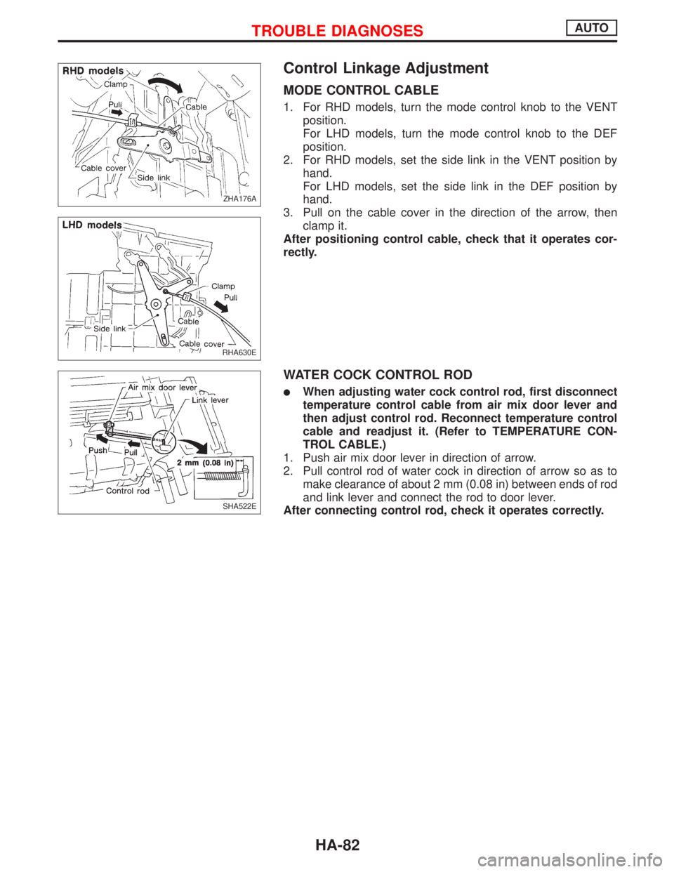
Control Linkage Adjustment
MODE CONTROL CABLE
1. For RHD models, turn the mode control knob to the VENT
position.
For LHD models, turn the mode control knob to the DEF
position.
2. For RHD models, set the side link in the VENT position by
hand.
For LHD models, set the side link in the DEF position by
hand.
3. Pull on the cable cover in the direction of the arrow, then
clamp it.
After positioning control cable, check that it operates cor-
rectly.
WATER COCK CONTROL ROD
lWhen adjusting water cock control rod, first disconnect
temperature control cable from air mix door lever and
then adjust control rod. Reconnect temperature control
cable and readjust it. (Refer to TEMPERATURE CON-
TROL CABLE.)
1. Push air mix door lever in direction of arrow.
2. Pull control rod of water cock in direction of arrow so as to
make clearance of about 2 mm (0.08 in) between ends of rod
and link lever and connect the rod to door lever.
After connecting control rod, check it operates correctly.
ZHA176A.ZHA176A
RHA630E
SHA522E
TROUBLE DIAGNOSESAUTO
HA-82
Page 1932 of 2267

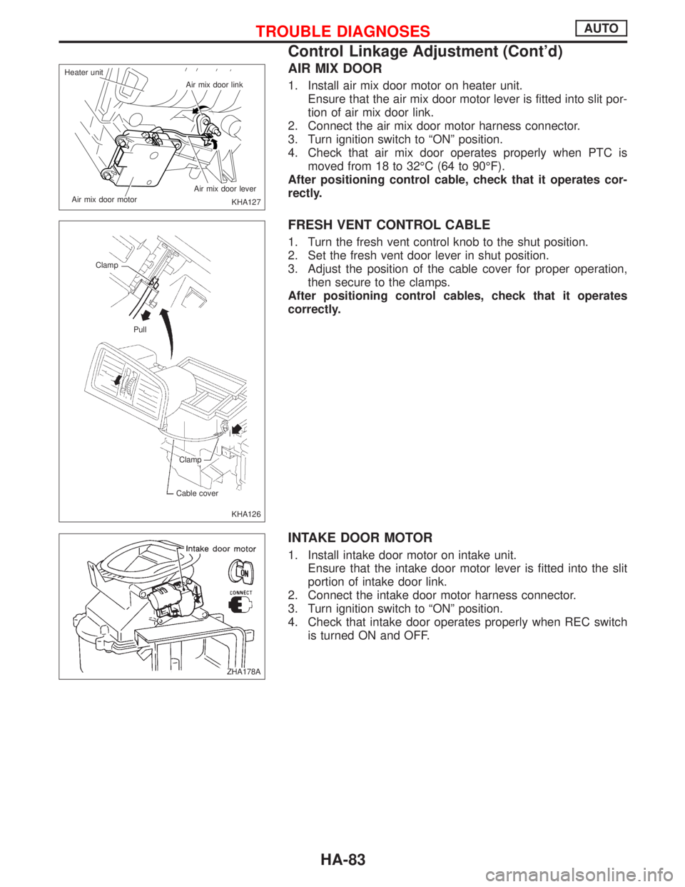
AIR MIX DOOR
1. Install air mix door motor on heater unit.
Ensure that the air mix door motor lever is fitted into slit por-
tion of air mix door link.
2. Connect the air mix door motor harness connector.
3. Turn ignition switch to ªONº position.
4. Check that air mix door operates properly when PTC is
moved from 18 to 32ÉC (64 to 90ÉF).
After positioning control cable, check that it operates cor-
rectly.
FRESH VENT CONTROL CABLE
1. Turn the fresh vent control knob to the shut position.
2. Set the fresh vent door lever in shut position.
3. Adjust the position of the cable cover for proper operation,
then secure to the clamps.
After positioning control cables, check that it operates
correctly.
INTAKE DOOR MOTOR
1. Install intake door motor on intake unit.
Ensure that the intake door motor lever is fitted into the slit
portion of intake door link.
2. Connect the intake door motor harness connector.
3. Turn ignition switch to ªONº position.
4. Check that intake door operates properly when REC switch
is turned ON and OFF.
KHA127 Air mix door link
Air mix door lever
Air mix door motor Heater unit
KHA126 Clamp
Pull
Clamp
Cable cover
ZHA178A
TROUBLE DIAGNOSESAUTO
Control Linkage Adjustment (Cont'd)
HA-83
Page 1933 of 2267
Overview of Control System
The control system consists of a) input sensors and switches, b)
the automatic amplifier (microcomputer), and c) outputs. The
relationship of these components is shown in the diagram below.
Control System Input Components
POTENTIO TEMPERATURE CONTROL (PTC)
The PTC is built into the control panel. It can be set at an inter-
val of 1ÉC in the 18ÉC to 32ÉC temperature range by pushing the
temperature button. The set temperature is digitally displayed.
Measure voltage between auto amp. terminal
p4and body
ground.
YHA295 A/C control panel
PTC
(Potentio temperature Con-
trol)
A/C switch
Autoswitch
Fan switch
Ambient sensor
In-vehicle sensor
sunload sensor
Thermal transmitterAutomatic ampli-
fier
(Micro-computer)
Air mix door motor
PBR (Potentio Balance Resistor-
)built-into air mix door motor
LOW, MED, HIGH and AUTOAir mix door
Blower motor
NHA294 Temperature
button
NHA315 Auto amp. connector
SYSTEM DESCRIPTIONAUTO
HA-84