Page 1989 of 2267
Cooling Fan Control SystemNCLC0026
Cooling fans are controlled by the ECM. For details, refer to EC
section [TROUBLE DIAGNOSIS FOR OVERHEAT (COOLING
SYSTEM)].
Refilling Engine CoolantNCLC0027
For details on refilling engine coolant, refer to MA section
(“ENGINE MAINTENANCE”,“Changing Engine Coolant”, MA-30)
ENGINE COOLING SYSTEMQG
Radiator (Cont’d)
LC-14
Page 2000 of 2267
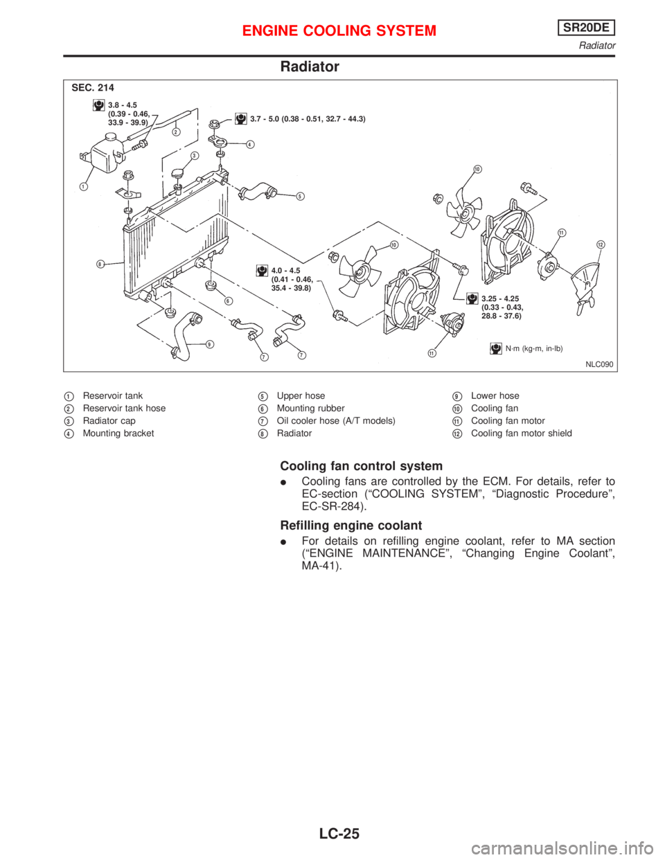
Radiator
�1Reservoir tank
�2Reservoir tank hose
�3Radiator cap
�4Mounting bracket
�5Upper hose
�6Mounting rubber
�7Oil cooler hose (A/T models)
�8Radiator
�9Lower hose
�10Cooling fan
�11Cooling fan motor
�12Cooling fan motor shield
Cooling fan control system
�Cooling fans are controlled by the ECM. For details, refer to
EC-section (“COOLING SYSTEM”,“Diagnostic Procedure”,
EC-SR-284).
Refilling engine coolant
�For details on refilling engine coolant, refer to MA section
(“ENGINE MAINTENANCE”,“Changing Engine Coolant”,
MA-41).
NLC090
3.8 - 4.5
(0.39 - 0.46,
33.9 - 39.9)
3.7 - 5.0 (0.38 - 0.51, 32.7 - 44.3)
4.0 - 4.5
(0.41 - 0.46,
35.4 - 39.8)
3.25 - 4.25
(0.33 - 0.43,
28.8 - 37.6)
�1
�2
�3�4
�5
�6
�7
�8
�9
�10
�11
�11
�10
�7
SEC. 214
�12
N·m (kg-m, in-lb)
ENGINE COOLING SYSTEMSR20DE
Radiator
LC-25
Page 2011 of 2267
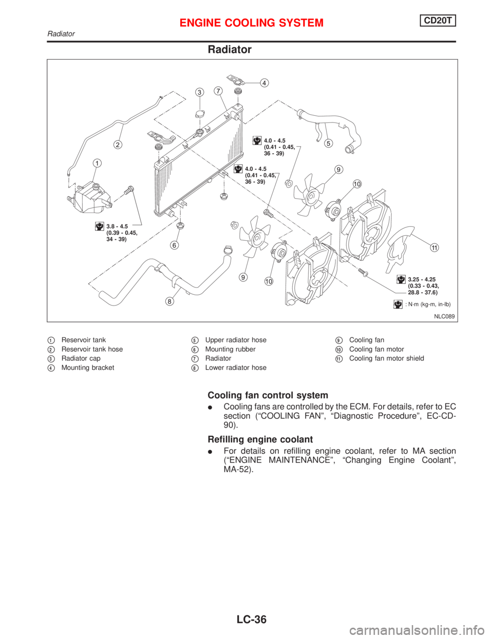
Radiator
�1Reservoir tank
�2Reservoir tank hose
�3Radiator cap
�4Mounting bracket
�5Upper radiator hose
�6Mounting rubber
�7Radiator
�8Lower radiator hose
�9Cooling fan
�10Cooling fan motor
�11Cooling fan motor shield
Cooling fan control system
�Cooling fans are controlled by the ECM. For details, refer to EC
section (“COOLING FAN”,“Diagnostic Procedure”, EC-CD-
90).
Refilling engine coolant
�For details on refilling engine coolant, refer to MA section
(“ENGINE MAINTENANCE”,“Changing Engine Coolant”,
MA-52).
NLC089
3.8 - 4.5
(0.39 - 0.45,
34 - 39)
4.0 - 4.5
(0.41 - 0.45,
36 - 39)
4.0 - 4.5
(0.41 - 0.45,
36 - 39)
3.25 - 4.25
(0.33 - 0.43,
28.8 - 37.6)
:N·m (kg-m, in-lb)
ENGINE COOLING SYSTEMCD20T
Radiator
LC-36
Page 2021 of 2267

Shown below are Pre-delivery Inspection Items required for the new vehicle. It is recommended that
necessary items other than those listed here be added, paying due regard to the conditions in each
country.
Perform applicable items on each model. Consult text of this section for specifications.
UNDER HOOD � engine off
Radiator coolant level and coolant hose con-
nections for leaks
Battery fluid level, specific gravity and condi-
tions of battery terminals
Drive belts tension
Fuel filter for water or dust, fuel lines and con-
nections for leaks
Engine oil level and oil leaks
Clutch and brake reservoir fluid level and fluid
lines for leaks
Windshield and rear window washer and head-
lamp cleaner reservoir fluid level
Power steering reservoir fluid level and hose
connections for leaks
ON INSIDE AND OUTSIDE
Remove front spring/strut spacer (If applicable)
Operation of all instruments, gauges, lights and
accessories
Operation of horn(s), wiper and washer
Steering lock for operation
Check air conditioner for gas leaks
Front and rear seats, and seat belts for opera-
tion
All moldings, trims and fittings for fit and align-
ment
All windows for operation and alignment
Hood, trunk lid, door panels for fit and align-
ment
Latches, keys and locks for operation
Weatherstrips for adhesion and fit
Headlamp aiming
Tighten wheel nuts (Inc. inner nuts if appli-
cable)
Tire pressure (Inc. spare tire)
Check front wheels for toe-in
Install clock/voltmeter/room lamp fuse (If appli-
cable)
Install deodorizing filter to air purifier (If appli-
cable)
Remove wiper blade protectors (If applicable)
UNDER BODY
Manual transmission/transaxle, transfer and
differential gear oil level
Brake and fuel lines and oil/fluid reservoirs for
leaks
Tighten bolts and nuts of steering linkage and
gear box, suspension, propeller shafts and
drive shafts
Tighten rear body bolts and nuts (Models with
wooden bed only)
ROAD TEST
Clutch operation
Parking brake operation
Service brake operation
Automatic transmission/transaxle shift timing
and kickdown
Steering control and returnability
Engine performance
Squeaks and rattles
ENGINE OPERATING AND HOT
Adjust idle mixture and speed (and ignition tim-
ing*1)
Automatic transmission/transaxle fluid level
Engine idling and stop knob operation (Diesel
only)
FINAL INSPECTION
Install necessary parts (outside mirror, wheel
covers, seat belts, mat, carpet or mud flaps)
Inspect for interior and exterior metal and paint
damage
Check for spare tire, jack, tools (wheel chock),
and literature
Wash, clean interior and exterior
*1: Not required on models with a direct ignition system
: Not applicable to this model.
PRE-DELIVERY INSPECTION ITEMS
MA-4
Page 2036 of 2267

Changing Engine Coolant
WARNING:
To avoid being scalded, never change the coolant when the
engine is hot.
—DRAINING ENGINE COOLANT—
Heater
1. Set heater system as follows to prevent coolant from remain-
ing in the system.
�Move temperature control dial all the way to“HOT”.
Semi-automatic air conditioning
1. Set air conditioning system as follows to prevent coolant from
remaining in the system.
a. Turn ignition switch“ON”and enter a temperature of 32°Con
the heater control.
b. Wait 30 seconds before turning ignition switch“OFF”.
2. Disconnect lower radiator hose and remove radiator cap.
3. Remove reservoir tank, drain coolant, then clean reservoir
tank.
Install it temporarily.
�Be careful not to allow coolant to contact drive belts.
4. Remove cylinder block drain plug and air relief plug.
5. Check drained coolant for contaminants such as rust, corro-
sion or discoloration.
If contaminated, flush engine cooling system.
Refer to“FLUSHING COOLING SYSTEM”, MA-21.
NMA104 Turn to HOT
Temperature control dial
NMA103 Temperature control
NMA051 Front
.Loosen
.Radiator cap
.Front.Lower
radiator
hose
NMA001 Drain plug
Loosen
Air relief plug
NMA107
ENGINE MAINTENANCEQG
MA-19
Page 2037 of 2267

—REFILLING ENGINE COOLANT—
6. Install lower radiator hose, reservoir tank and tighten cylinder
block drain plug securely.
�Apply sealant to the thread of the cylinder block drain
plug.
:34-44N·m (3.5 - 4.5 kg-m, 25 - 33 ft-lb)
7. Fill up radiator with coolant at the speed of less than 3�(2-5/8
Imp qt)/min.
�If coolant spills from the air relief hole without bubbles, rein-
stall the plug.
Air relief plug:
:7-8N·m (0,7 - 0,8 kg-m, 5,1 - 5,8 ft-lb)
Then pour coolant in again.
�Use genuine NISSAN Anti-Freeze Coolant or equivalent.
Refer to“RECOMMENDED FLUIDS AND LUBRICANTS”,
MA-16.
Coolant capacity (With reservoir tank):
Unit: (Imp qt)
QG16DE/QG18DE6.1 (5-3/8)
8. Fill radiator and reservoir tank to specified level.
9. Start engine without installing radiator cap and warm it up at
2,000 rpm until radiator lower hose becomes hot.
�If coolant level becomes low, refill coolant until coolant level
does not change.
�If coolant overflows radiator filler hole, install filler cap.
10. Run engine at 2,500 rpm for 10 seconds and return to idle
speed.
�Repeat 2 or 3 times.
Watch coolant temperature gauge so as not to overheat the
engine.
11. Stop engine and wait until it cools down.
�If necessary, refill radiator up to filler neck.
12. Refill reservoir tank to Max line with coolant.
13. Repeat steps 9 through 12 two or more times with radiator
cap installed until coolant level no longer drops.
14. Check cooling system for leaks with engine running.
15. Warm up engine, and check for sound of coolant flow while
running engine from idle up to 3,000 rpm with heater tem-
perature control set at several positions between COOL and
HOT.
�Sound may be noticeable at heater water cock.
16. If the sound is heard, bleed air from cooling system by
repeating steps 9 through 12 until coolant level no longer
drops.
SMA182B Radiator
SMA412B MAX.
MIN.
ENGINE MAINTENANCEQG
Changing Engine Coolant (Cont’d)
MA-20
Page 2043 of 2267
 System
CHECKING PCV VALVE
With engine running at idle, disconnect ventilation hose from
PCV valve. If valve is working correctly, a hissing noise will be")
Checking Positive Crankcase Ventilation
(PCV) System
CHECKING PCV VALVE
With engine running at idle, disconnect ventilation hose from
PCV valve. If valve is working correctly, a hissing noise will be
heard as air passes through it, and a strong vacuum should be
felt immediately when a finger is placed over valve inlet.
CHECKING VENTILATION HOSES
1. Check hoses and hose connections for leaks.
2. Disconnect all hoses and clean with compressed air. If any
hose cannot be freed of obstructions, replace.
Checking Vacuum Hoses and Connections
Check vacuum hoses for leaks, cracks, damage, loose
connections, chafing and deterioration.
Refer to Vacuum Hose Drawing in EMISSION CONTROL
OVERALL SYSTEM in EC section.
Checking EVAP Vapour Lines
1. Visually inspect vapor lines for leaks, cracks, damage, loose
connections, chafing and deterioration.
2. Inspect vacuum relief valve of fuel tank filler cap for clogging,
sticking, etc.
Refer to EVAPORATIVE EMISSION CONTROL SYSTEM
INSPECTION in EC section.
SMA048
SMA275C Vapor line
Purge line
ENGINE MAINTENANCEQG
MA-26
Page 2046 of 2267

Changing Engine Coolant
WARNING:
To avoid being scalded, never change the coolant when the
engine is hot.
Heater
—DRAINING ENGINE COOLANT—
1. Set heater system as follows to prevent coolant from remain-
ing in the system.
�Move temperature control dial all the way to“HOT”.
Semi-automatic air conditioning
1. Set air conditioner system as follows to prevent coolant from
remaining in the system.
a. Turn ignition switch“ON”and enter a temperature of 32°Con
the heater control.
b. Wait 30 seconds before turning ignition switch“OFF”.
2. Disconnect lower radiator hose and remove radiator cap.
3. Remove reservoir tank, drain coolant, then clean reservoir
tank.
Install it temporarily.
�Be careful not to allow coolant to contact drive belts.
SMA328C Alternator drive belt fitting place
(Models without air conditioner)
Alternator drive belt
Crankshaft pulley
Engine
front
Alternator drive belt
Engine
front
Alternator
pulley Set a belt in both crankshaft
and alternator pulleys as
shown in the figure.
NMA104 Turn to HOT
Temperature control dial
NMA103 Temperature control
.SMA285C Lower radiator
hose
Remove
ENGINE MAINTENANCESR20DE
Checking Drive Belts (Cont’d)
MA-29
![NISSAN PRIMERA 1999 Electronic Repair Manual Cooling Fan Control SystemNCLC0026
Cooling fans are controlled by the ECM. For details, refer to EC
section [TROUBLE DIAGNOSIS FOR OVERHEAT (COOLING
SYSTEM)].
Refilling Engine CoolantNCLC0027
For deta](/manual-img/5/57377/w960_57377-1988.png "NISSAN PRIMERA 1999 Electronic Repair Manual Cooling Fan Control SystemNCLC0026
Cooling fans are controlled by the ECM. For details, refer to EC
section [TROUBLE DIAGNOSIS FOR OVERHEAT (COOLING
SYSTEM)].
Refilling Engine CoolantNCLC0027
For deta")