Page 2127 of 2267

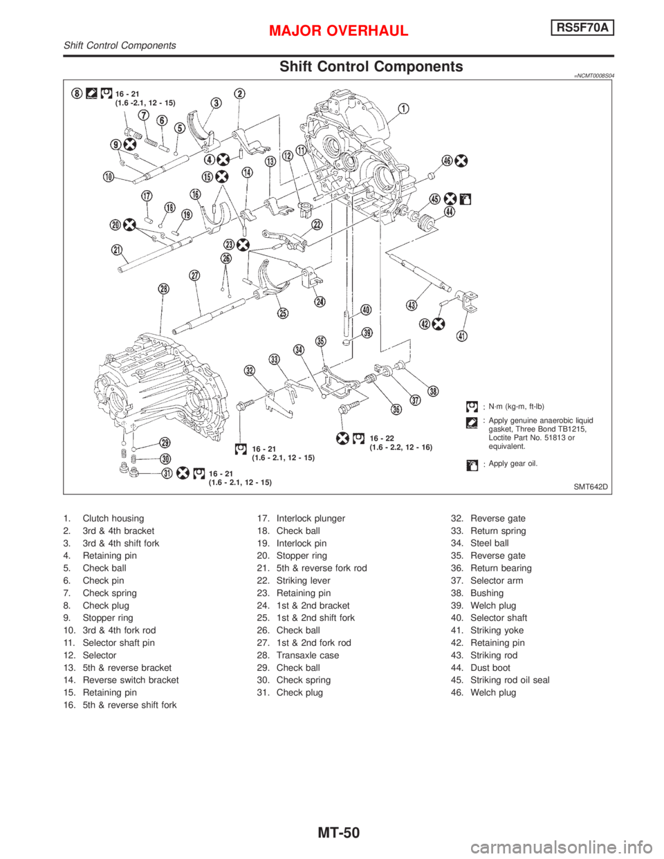
Shift Control Components=NCMT0008S04
1. Clutch housing
2. 3rd & 4th bracket
3. 3rd & 4th shift fork
4. Retaining pin
5. Check ball
6. Check pin
7. Check spring
8. Check plug
9. Stopper ring
10. 3rd & 4th fork rod
11. Selector shaft pin
12. Selector
13. 5th & reverse bracket
14. Reverse switch bracket
15. Retaining pin
16. 5th & reverse shift fork17. Interlock plunger
18. Check ball
19. Interlock pin
20. Stopper ring
21. 5th & reverse fork rod
22. Striking lever
23. Retaining pin
24. 1st & 2nd bracket
25. 1st & 2nd shift fork
26. Check ball
27. 1st & 2nd fork rod
28. Transaxle case
29. Check ball
30. Check spring
31. Check plug32. Reverse gate
33. Return spring
34. Steel ball
35. Reverse gate
36. Return bearing
37. Selector arm
38. Bushing
39. Welch plug
40. Selector shaft
41. Striking yoke
42. Retaining pin
43. Striking rod
44. Dust boot
45. Striking rod oil seal
46. Welch plug
SMT642D 16-21
(1.6 -2.1, 12 - 15)
16-21
(1.6 - 2.1, 12 - 15)16-21
(1.6 - 2.1, 12 - 15)16-22
(1.6 - 2.2, 12 - 16)N´m (kg-m, ft-lb)
Apply genuine anaerobic liquid
gasket, Three Bond TB1215,
Loctite Part No. 51813 or
equivalent.
Apply gear oil.
MAJOR OVERHAULRS5F70A
Shift Control Components
MT-50
Page 2151 of 2267

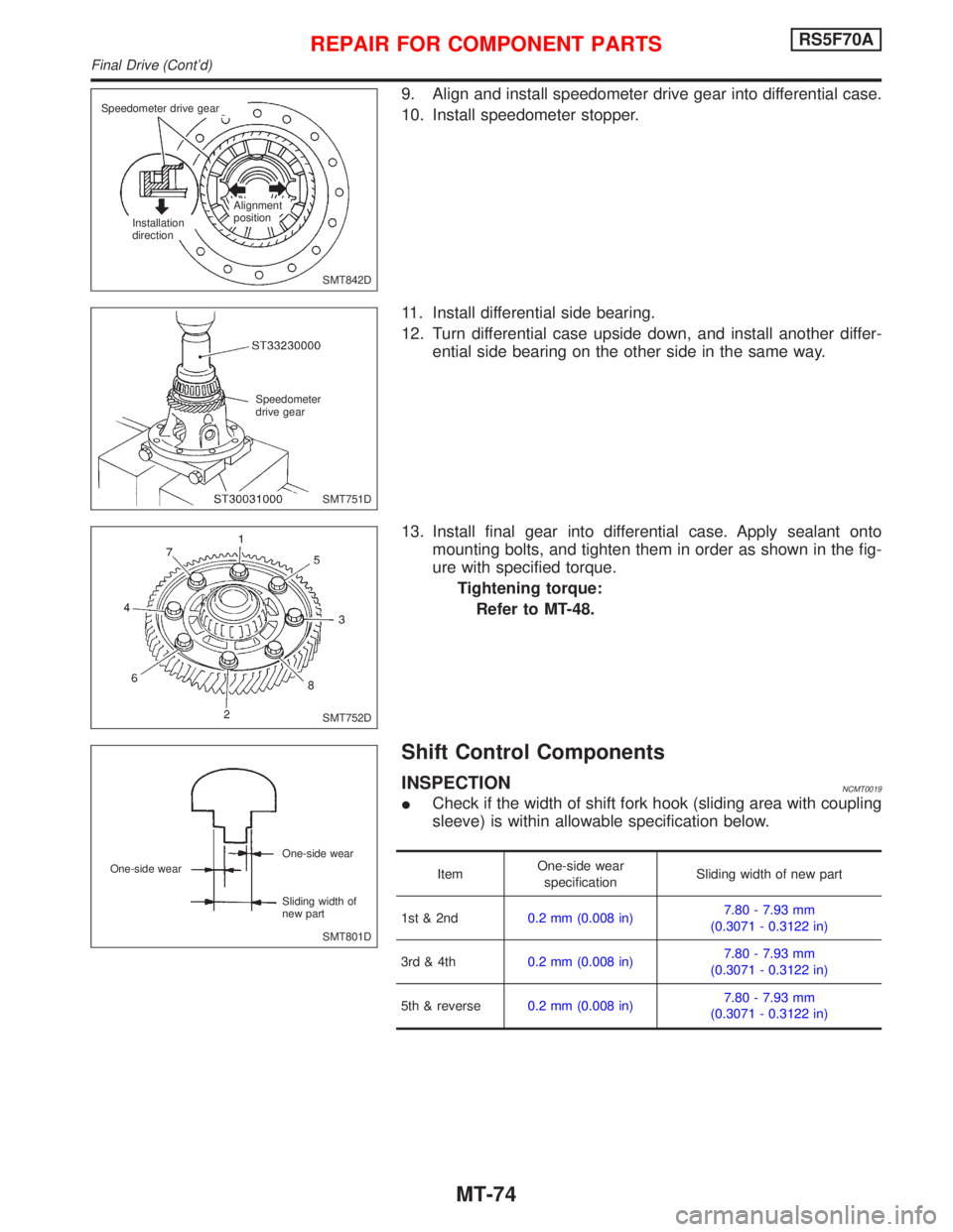
9. Align and install speedometer drive gear into differential case.
10. Install speedometer stopper.
11. Install differential side bearing.
12. Turn differential case upside down, and install another differ-
ential side bearing on the other side in the same way.
13. Install final gear into differential case. Apply sealant onto
mounting bolts, and tighten them in order as shown in the fig-
ure with specified torque.
Tightening torque:
Refer to MT-48.
Shift Control Components
INSPECTIONNCMT0019
ICheck if the width of shift fork hook (sliding area with coupling
sleeve) is within allowable specification below.
ItemOne-side wear
specificationSliding width of new part
1st & 2nd0.2 mm (0.008 in)7.80 - 7.93 mm
(0.3071 - 0.3122 in)
3rd & 4th0.2 mm (0.008 in)7.80 - 7.93 mm
(0.3071 - 0.3122 in)
5th & reverse0.2 mm (0.008 in)7.80 - 7.93 mm
(0.3071 - 0.3122 in)
SMT842D Speedometer drive gear
Installation
directionAlignment
position
SMT751D Speedometer
drive gear
SMT752D
SMT801D One-side wear
Sliding width of
new part One-side wear
REPAIR FOR COMPONENT PARTSRS5F70A
Final Drive (Cont'd)
MT-74
Page 2152 of 2267
ICheck if shift check groove of fork rod or 5th & reverse check
groove is worn, or has any other abnormalities.
SMT692D 1st & 2nd fork rod
5th & reverse fork rod
3rd & 4th fork rod
REPAIR FOR COMPONENT PARTSRS5F70A
Shift Control Components (Cont'd)
MT-75
Page 2166 of 2267
INPUT SHAFT BRAKING MECHANISM
SMT735B 1st & 2nd shifter
Striking lever
Reverse brake cam Control bracket
fitting surface
Maximum height ªHº between the
control bracket fitting surface and
1-2 shifter
mm (in)67.16 - 67.64
(2.6441 - 2.6630)
SMT736B Reverse brake cam
Striking lever
Clearance ªCº between reverse
brake cam and striking lever
mm (in)0.05 - 0.125
(0.0020 - 0.0049)
MAINSHAFT END PLAY
Mainshaft end play
(Clearance between end of case cover and
mainshaft rear bearing outer race)0 - 0.1 mm
(0 - 0.004 in)
Case cover
SMT760B T
Thickness ªTº mm (in) Part No.
10.78 (0.4244) 32131-50J00
10.83 (0.4264) 32131-50J01
10.88 (0.4283) 32131-50J02
10.93 (0.4303) 32131-50J03
10.98 (0.4323) 32131-50J04
11.03 (0.4343) 32131-50J05
SERVICE DATA AND SPECIFICATIONS (SDS)RS5F32A
Inspection and Adjustment Ð RS5F32A (Cont'd)
MT-89
Page 2170 of 2267

REAR AXLE &
REAR SUSPENSION
SECTION
RA
CONTENTS
PRECAUTIONS AND PREPARATION.......................... 2
Precautions ................................................................ 2
Special Service Tools ................................................ 2
Commercial Service Tools ......................................... 2
NOISE, VIBRATION AND HARSHNESS (NVH)
TROUBLESHOOTING................................................... 3
NVH Troubleshooting Chart....................................... 3
REAR SUSPENSION SYSTEM..................................... 4
ON-VEHICLE SERVICE................................................ 5
Rear Axle and Rear Suspension Parts ..................... 5
Rear Wheel Bearing .................................................. 5Rear Wheel Alignment ............................................... 6
REAR AXLE................................................................... 7
Wheel Hub ................................................................. 7
REAR SUSPENSION..................................................... 9
Removal and Installation ......................................... 10
Coil Spring and Shock Absorber .............................. 11
Torsion Beam, Lateral Link and Control Rod .......... 12
SERVICE DATA AND SPECIFICATIONS (SDS)........ 14
General Specifications ............................................. 14
Inspection and Adjustment ...................................... 14
RA
Page 2173 of 2267
p1Coil spring
p2Shock absorberp3Torsion beam
p4Lateral linkp5Control rod
NRA004
98 - 118 (10 - 12, 73 - 87)
42-57
(4.3 - 5.8, 31 - 42)
p1
p2
p3
p4
p5
98 - 118 (10 - 12, 73 - 87) Front
: Do not re-use
: N´m (kg-m, ft-lb)
SEC. 431
When installing each rubber part, final tightening
must be carried out under unladen condition*
with tires on ground.
* Fuel, radiator coolant and engine oil full.
Spare tire, jack, hand tools and mats in
designated positions.
REAR SUSPENSION SYSTEM
RA-4
Page 2178 of 2267
p1Washer
p2Bushing
p3Shock absorber mounting
bracket
p4Bound bumper cover
p5Bound bumper
p6Coil spring
p7Shock absorber
p8Torsion beam
p9Lateral link
p10Control rod
p11ABS sensor
NRA018
SEC. 431
When installing each rubber part, final tightening
must be carried out under unladen condition*
with tires on ground.
* Fuel, radiator coolant and engine oil full.
Spare tire, jack, hand tools and mats in
designated positions.
36 - 47 (3.7 - 4.7, 27 - 34)
p1
p2
p3
42-57
(4.3 - 5.8,
31 - 42)
p4
p5
p6
p7
25-33
(2.6 - 3.3,
19 - 24)
p8
98-118
(10 - 12, 73 - 87)p9
p10
98-118
(10 - 12,
73 - 87)
59-78
(6.1 - 7.9,
44 - 57)
Front
98 - 118 (10 - 12, 73 - 87)
p11
98-118
(10 - 12, 73 - 87)
: N´m (kg-m, ft-lb)
: Do not re-use
98 - 118 (10 - 12, 73 - 87)
REAR SUSPENSION
RA-9
Page 2179 of 2267

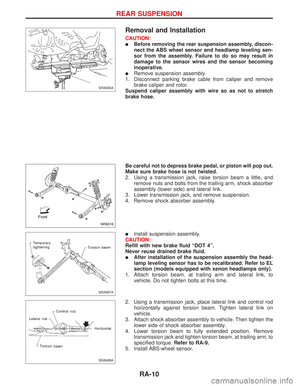
Removal and Installation
CAUTION:
lBefore removing the rear suspension assembly, discon-
nect the ABS wheel sensor and headlamp leveling sen-
sor from the assembly. Failure to do so may result in
damage to the sensor wires and the sensor becoming
inoperative.
lRemove suspension assembly.
1. Disconnect parking brake cable from caliper and remove
brake caliper and rotor.
Suspend caliper assembly with wire so as not to stretch
brake hose.
Be careful not to depress brake pedal, or piston will pop out.
Make sure brake hose is not twisted.
2. Using a transmission jack, raise torsion beam a little, and
remove nuts and bolts from the trailing arm, shock absorber
assembly (lower side) and lateral link.
3. Lower transmission jack, and remove suspension.
4. Remove shock absorber assembly.
lInstall suspension assembly.
CAUTION:
Refill with new brake fluid ªDOT 4º.
Never reuse drained brake fluid.
lAfter installation of the suspension assembly the head-
lamp leveling sensor has to be recalibrated. Refer to EL
section (models equipped with xenon headlamps only).
1. Attach torsion beam, at trailing arm and lateral link, to
vehicle. Do not tighten bolts at this time.
2. Using a transmission jack, place lateral link and control rod
horizontally against torsion beam. Tighten lateral link on
vehicle.
3. Attach shock absorber assembly to vehicle. Then tighten the
lower side of shock absorber assembly.
4. Lower torsion beam to fully extended position. Remove
transmission jack and tighten torsion beam, at trailing arm, to
specified torque.Refer to RA-9.
5. Install ABS-wheel sensor.
SRA695A
NRA016
SRA697A
SRA698A
REAR SUSPENSION
RA-10