Page 2087 of 2267
RemovalNCMT0007S01
1. Remove battery negative terminal.
2. Remove air duct.
3. Disconnect clutch control cable from transaxle (GA16 models).
4. Remove clutch operating cylinder from transaxle (except GA16
models).
5. Disconnect back-up lamp switch, speedometer sensor, neutral
position switch and ground harness connectors.
6. Remove starter motor from transaxle.
7. Remove shift control rod and support rod from transaxle.
8. Drain gear oil from transaxle.
9. Remove exhaust front tube.
10. Draw out drive shafts from transaxle Ð Refer to section FA.
.SMT653B Front
SMT654B
.Starter motor
Front
SMT655B Shift control rod
Shift support rod
.F31A and F32A
NMT091
.Control rod
.Support rod
.F70A
SMT656B Knuckle
spindle
upper nutDrive shaft
REMOVAL AND INSTALLATION
Removal
MT-10
Page 2091 of 2267
Transaxle Gear Control
p1Control lever knob
p2Boot
p3Control lever socket
p4Control lever
p5Bushing
p6Hand lever socket
p7Plate bolt
p8Transaxle hole cover
p9Support rod
p10Plate
p11Collar
p12Bushing
p13Collar
p14Bushing
p15Control rod
p16Return spring
p17Holder bracket
p18Dynamic damper
NMT097
14 - 18 (1.4 - 1.8, 10 - 13)
18 - 24 (1.8 - 2.4, 13 - 17)
22 - 29 (2.2 - 3.0, 16 - 22)
12-15
(1.2-1.5,9-11)
4.4 - 5.9 (0.45 - 0.60, 39.1 - 52.1)
12-15
(1.2-1.5,9-11)
43-55
(4.4 - 5.6,
32 - 41)
SEC. 341
: Apply multi purpose grease
: N´m (kg-m, in-lb)
: N´m (kg-m, ft-lb)
MAJOR OVERHAULRS5F32A
Transaxle Gear Control
MT-14
Page 2094 of 2267
Shift Control Components
p1Check plunger
p2Select return spring
p3O-ring
p4Check sleeve
p5Striking lever
p6Snap ring
p7Striking interlock
p8Reverse brake cam
p9Reverse brake cam spring
p10Check ball plug
p11Shift check ball
p12Check spring
p13Fork shaft support spring
p14Fork shaft
p155th shift fork
p16Shifter cap
p173rd & 4th shift fork
p18Shifter cap
p191st & 2nd shift fork
p20Control bracket
p21Control bracket pin
p22Retaining pin
p23Striking rod
p24Retaining pin
p25Yoke
p26Reverse check plug
p27Check ball (Large)
p28Check ball (Small)
p29Stopper pin
NMT025
.
.6.3 - 8.3
(0.64 0.85, 55.6 - 73.8)
12-16
(1.2 - 1.6, 9 - 12)
6.3 - 8.3
(0.64 - 0.85, 55.6 - 73.8)
.:
:
:
:
pL:
H:
I:
Apply gear oil
Do not re-use
N´m (kg-m, ft-lb)
N´m (kg-m, in-lb)
Apply locking sealant
Select correct length
Select correct part. Adjustment required
SEC. 328
MAJOR OVERHAULRS5F32A
Shift Control Components
MT-17
Page 2096 of 2267
6. Remove control bracket with 1st & 2nd shift fork.
7. Remove gear components from clutch housing.
a. Remove input shaft front bearing retainer securing bolts.
b. Remove input shaft with bearing retainer, mainshaft assembly
and reverse idler gear.
IAlways withdraw mainshaft straight out. Failure to do so
can damage resin oil channel on clutch housing side.
IDo not draw out reverse idler shaft from clutch housing
because these fittings will be loose.
When removing input shaft, be careful not to scratch oil
seal lip with shaft spline.
c. Remove final drive assembly.
8. Remove oil pocket, shift check ball, check spring and check
ball plug.
IBe careful not to lose check ball.
SMT668B
.1st & 2nd shift
fork
Control bracket
SMT669B Bearing retainer
SMT670B
SMT671B
SMT648A Check spring
Shift check ball
Check ball plug
DISASSEMBLYRS5F32A
MT-19
Page 2112 of 2267
Shift Control Components
INSPECTION
ICheck contact surface and sliding surface for wear, scratches,
projections or other damage.
SMT703B Striking rod
Control bracket
Shift fork and
shifter cap
SMT727B
REPAIR FOR COMPONENT PARTSRS5F32A
Shift Control Components
MT-35
Page 2113 of 2267

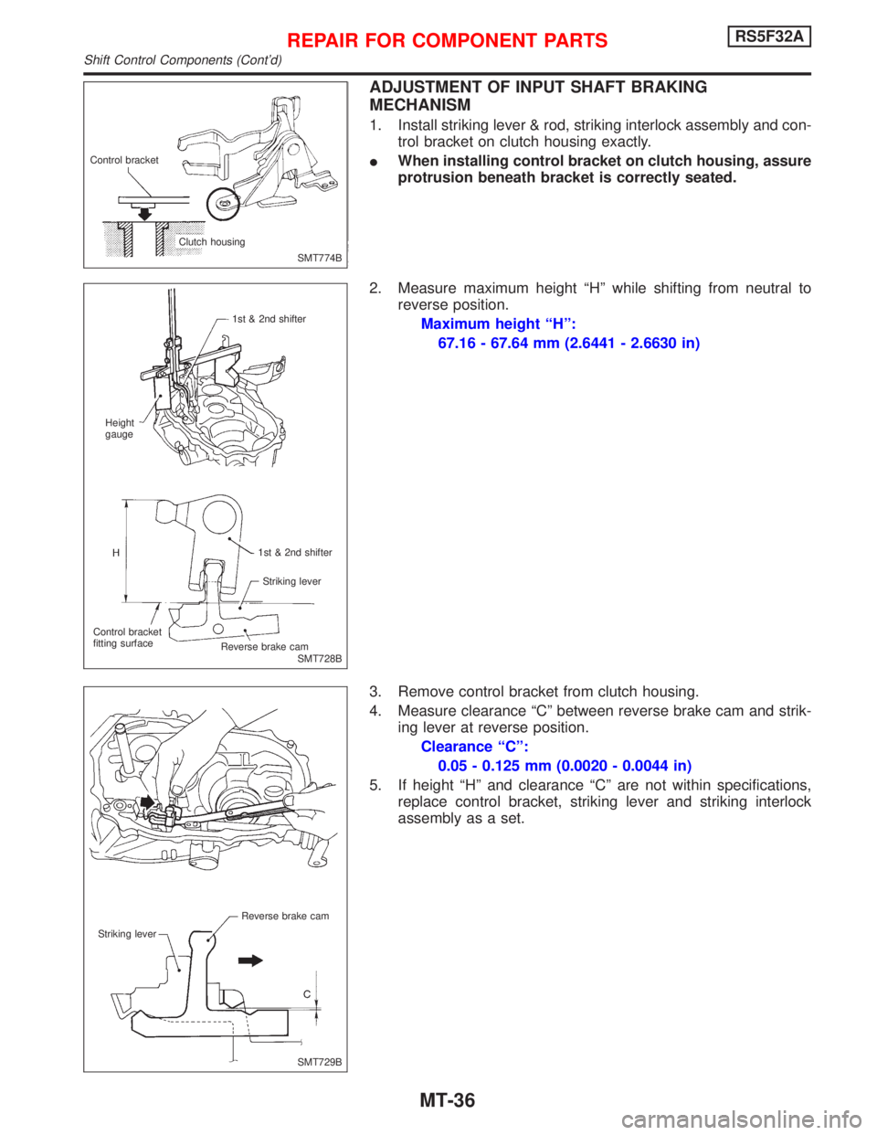
ADJUSTMENT OF INPUT SHAFT BRAKING
MECHANISM
1. Install striking lever & rod, striking interlock assembly and con-
trol bracket on clutch housing exactly.
IWhen installing control bracket on clutch housing, assure
protrusion beneath bracket is correctly seated.
2. Measure maximum height ªHº while shifting from neutral to
reverse position.
Maximum height ªHº:
67.16 - 67.64 mm (2.6441 - 2.6630 in)
3. Remove control bracket from clutch housing.
4. Measure clearance ªCº between reverse brake cam and strik-
ing lever at reverse position.
Clearance ªCº:
0.05 - 0.125 mm (0.0020 - 0.0044 in)
5. If height ªHº and clearance ªCº are not within specifications,
replace control bracket, striking lever and striking interlock
assembly as a set.
SMT774B Control bracket
Clutch housing
SMT728B 1st & 2nd shifter
Height
gauge
1st & 2nd shifter
Striking lever
Control bracket
fitting surface
.Reverse brake cam
SMT729B Reverse brake cam
Striking lever
REPAIR FOR COMPONENT PARTSRS5F32A
Shift Control Components (Cont'd)
MT-36
Page 2119 of 2267
b. Install input shaft assembly with bearing retainer, mainshaft
assembly and reverse idler gear.
IBe careful not to damage oil seal lip with splines of input
shaft while shaft is being inserted into clutch housing.
IBe careful not to damage oil channel when inserting main-
shaft into clutch housing.
c. Install input shaft front bearing retainer.
9. Apply grease to shifter caps, then install it to control bracket.
Install control bracket with 1st & 2nd shift fork.
IEnsure control bracket is seated correctly on clutch hous-
ing.
10. Install 3rd & 4th and 5th shift forks.
11. Insert fork shaft.
IApply multi-purpose grease to support spring before
installing.
12. Install reverse idler spacer.
.SMT670B
.SMT669B Bearing retainer
SMT666
SMT774B Control bracket
Clutch housing
SMT596
ASSEMBLYRS5F32A
MT-42
Page 2124 of 2267
NCMT0008
Transaxle Gear ControlNCMT0008S01
1. Control lever knob
2. Boot
3. Finisher
4. Control lever bracket
5. Dust cover
6. Socket
7. Control lever8. O-ring
9. O-ring
10. Ring spring
11. Bearing seat
12. Seat
13. Return spring
14. Control rod15. Bush
16. Collar
17. Bush
18. Bracket
19. Bush
20. Collar
21. Washer
SMT135D
4.4 - 5.9 (0.45 - 0.60, 39 - 52)
12-15(1.2-1.5,9-11)
18 -24 (1.8 -2.4, 13 - 17)
12-15(1.2-1.5,9-11)
Apply multi-purpose grease.
N´m (kg-m, in-lb)
N´m (kg-m, ft-lb)
14 - 18 (1.4 - 1.8, 10 -13)29 - 37 (3.0 - 3.8, 21 - 27)
22 - 29 (2.2 - 3.0, 16 - 22)
MAJOR OVERHAULRS5F70A
Transaxle Gear Control
MT-47