Page 1402 of 1701
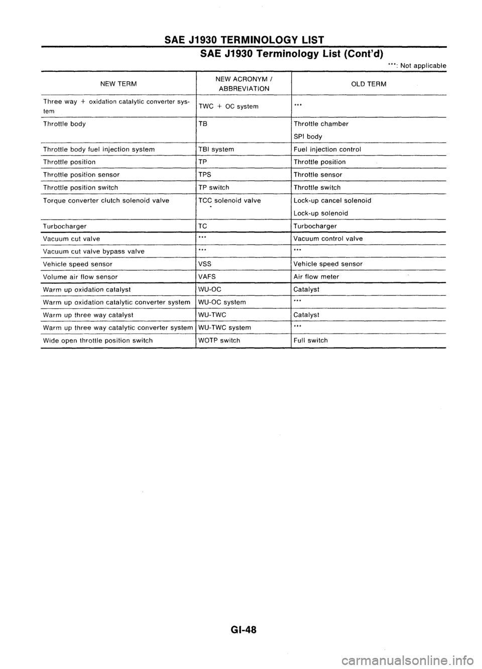
SAEJ1930 TERMINOLOGY LIST
SAE J1930 Terminology List(Cont'd)
"':Not applicable
NEW TERM NEW
ACRONYM
I
OLDTERM
ABBREVIATION
Three way
+
oxidation catalyticconverter sys-
TWC
+
OC system
..
,
tem
Throttle body TBThrottlechamber
SPI body
Throttle bodyfuelinjection system TBI
system
Fuelinjection control
Throttle position TP
Throttleposition
Throttle position sensor TPSThrottlesensor
Throttle position switch
TP
switch Throttleswitch
Torque converter clutchsolenoid valve TCCsolenoid valve Lock-upcancelsolenoid
.
Lock-upsolenoid
Turbocharger TC
Turbocharger
Vacuum cutvalve
..
,
Vacuumcontrolvalve
Vacuum cutvalve bypass valve
..
,
...
Vehicle speedsensor VSS
Vehiclespeedsensor
Volume airflow sensor VAFSAir
flow meter
Warm upoxidation catalyst WU-OC
Catalyst
Warm upoxidation catalyticconverter systemWU-OC
system
..
,
Warm upthree waycatalyst WU-TWC
Catalyst
Warm upthree waycatalytic converter systemWU-TWC system
..
,
Wide open throttle position switch WOTP
switch Fullswitch
GI-48
Page 1406 of 1701
PRECAUTIONSANDPREPARATION
Precautions forRefrigerant Connection
WARNING: Make sureallrefrigerant isdischarged intotherecycling equipment andthepressure inthe system is
less than atmospheric pressure.Thengradually loosenthedischarge sidehose fitting andremove it.
CAUTION:
When replacing orcleaning refrigerant cyclecomponents, observethefollowing.
• When thecompressor isremoved, storeitin the same position asitis when mounted onthe car.
Failure todo sowill cause lubricant toenter thelow pressure chamber.
• When connecting tubes,always useatorque wrench andaback-up wrench.
• After disconnecting tubes,immediately plugallopenings toprevent entryofdirt and moisture.
• When installing anair conditioner inthe vehicle, connect thepipes asthe final stage ofthe opera-
tion. Donot remove theseal caps ofpipes andother components untiljustbefore required forcon-
nection.
• Allow components storedincool areas towarm toworking areatemperature beforeremoving seal
caps. Thisprevents condensation fromforming inside
AIC
components.
• Thoroughly removemoisture fromtherefrigeration systembeforecharging therefrigerant.
• Always replace usedO-rings.
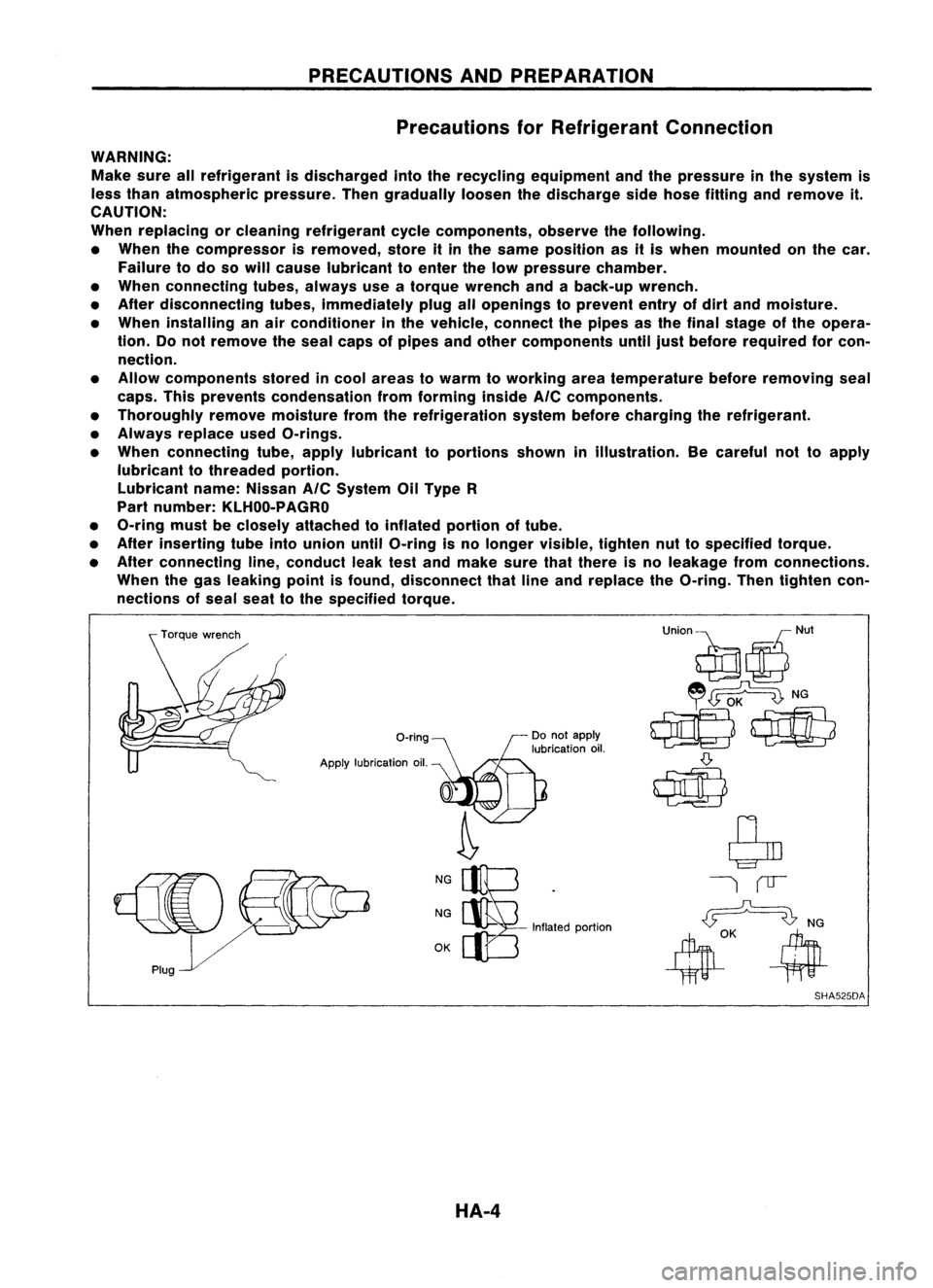
• When connecting tube,apply lubricant toportions showninillustration. Becareful nottoapply
lubricant tothreaded portion.
Lubricant name:Nissan
AIC
System OilType R
Part number: KLHOO-PAGRO
• O-ring mustbeclosely attached toinflated portionoftube.
• After inserting tubeintounion untilO-ring isno longer visible, tightennuttospecified torque.
• After connecting line,conduct leaktestand make surethatthere isno leakage fromconnections.
When thegas leaking pointisfound, disconnect thatlineand replace theO-ring. Thentighten con-
nections ofseal seattothe specified torque.
O-ring
Apply lubrication oil.
NG
NG
OK -
Inflated portion
SHA525DA
HA-4
Page 1471 of 1701
SERVICEPROCEDURES
Maintenance ofLubricant Quantityin
Compressor (Cont'd)
@
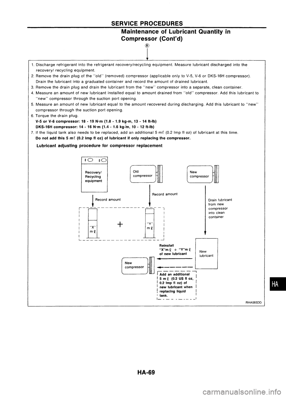
1. Discharge refrigerant intotherefrigerant recovery/recycling equipment.Measurelubricantdischarged intothe
recovery/ recyclingequipment.
2. Remove thedrain plugofthe "old" (removed) compressor (applicableonlytoV-5, V-6orDKS-16H compressor).
Drain thelubricant intoagraduated containerandrecord theamount ofdrained lubricant.
3. Remove thedrain pluganddrain thelubricant fromthe"new" compressor intoaseparate, cleancontainer.
4. Measure anamount ofnew lubricant installedequaltoamount drained from"old" compressor. Addthislubricant to
"new" compressor throughthesuction portopening.
5. Measure anamount ofnew lubricant equaltothe amount recovered duringdischarging. Addthislubricant to"new"
compressor throughthesuction portopening.
6. Torque thedrain plug.
V.5 orV-6 compressor: 18-19 N'm (1.8-1.9 kg-m, 13-14 ft-Ib)
DKS.16H compressor: 14-16 N'm (1.4-1.6 kg-in, 10-12 ft-Ib)
7. Ifthe liquid tankalso needs tobe replaced, addanadditional 5mC (0.2 Imp IIoz) oflubricant atthis time.
Do not add this5m C(0.2 ImpIIoz) oflubricant ifonly replacing thecompressor.
Lubricant adjustingprocedure forcompressor replacement
DO DO
Oldcompressor
Recovery/
Recycling
eqUipment
!
Roo'"
,m,,",
1
R,,,,'
,moo",
,--------------------,
I I
I I
I + I
I "Y"I
I "X"
mQ
I
I
mQ
I
I I
L ~
New
compressor
Drainlubricant
from new
compressor
into clean
container
------ L-...
.J
New
compressor
HA-69
Reinstall
"X"m
Q
+
"Y"m
Q
of new lubricant
-.-------
fAdda;-addition;;
"I
15m
Q
(0.2 USfl
Ol,
I 0.2
Imp
fl
Ol)
of
I
I new lubricant when
I
!
replacing liquid I
, tank. I
1- -__ I
New
lubricant
RHA065DD
•
Page 1472 of 1701
SERVICEPROCEDURES
Refrigerant Lines
• Refer topage HA-4regarding "Precautions forRefrigerant
Connection" .
GA ENGINE
RHO
MODEL
SEC. 271.274.276
fil10'20(1.0 .2.0, 87.174)
8
mm
dia.
Liquidtank
Condenser Expansion
valve
[O;J
15-25 (1.5 -2.5, 11-18)
12
mm
dia.
Low-pressure(Suction)
service valve
o
(Tightening torque)
o
0
(Wrench size)
o
(O-ring size)
[O;J :
N.m (kg-m, ft-Ib)
rn :
20 •29 (2.0 •3.0, 14-22)
fiI :
N.m (kg-m, in-Ib)
IBl :
8 •11 (0.8 -1.1, 69-95)
[C] :
10 -20 (1.0 -2.0, 87-174)
~ :3 -4 (0.3 -0.4, 26-35)
RHA332F
HA-70
Page 1475 of 1701
SERVICEPROCEDURES
Refrigerant Lines(Cont'd)
GA ENGINE lHDMODEL
SEC. 271.274.276
Low-pressure (Suction)servicevalve
~
10-20 (1.0 -2.0, 87-174)
6 mm (0.24 in)dia.
Thermo controlamp.
•
Dual-pressure
switch
~ Liquid tank
High-pressure
(Discharge) servicevalve
High-pressure
(Discharge) servicevalve
o
(Tightening torque)
D D (Wrench size)
D (O-ring size)
~ :N'm (kg-m, ft-lb)
~ :25 -34 (2.5 -3.5, 18-25)
~ :N'm (kg-m, in-Ib)
rm :
10 -20 (1.0 -2.0, 87-174)
~ :8 •11 (0.8 •1.1, 69•95)
~ :2.9 •3.9 (0.3 -0.4, 26•35)
~
15•20 (1.5 -2.0, 11-14)
~ 8
mm
(0.31
in)
die.
___ ==- - ~
20-25
(2.0 -2.5, 14-18)
."""\ ~t;,
12mm (0.47 in)dia.
Expansion valve
RHA334F
HA-73
Page 1476 of 1701
SERVICEPROCEDURES
Refrigerant Lines
(Cont'd)
CD ENGINE LHDMODEL
SEC. 271'274'276
[O.J
15. 20(1.5 -2.0, 11-14)
8
mm
(0.31
in)
dia.
[O.J
20-25 (2.0 -2.5, 14-18)
12 mm (0.47 in)dia.
~ 10•20 (1.0 -2.0, 87•174)
6 mm (0.24 in)dia.
Thermo controlamp.
High-pressure (Discharge)servicevalve
o
(Tightening torque)
o
0
(Wrench size)
o
(O-ring size)
[O.J :
N'm (kg-m, It-Ib)
B :
25 -34 (2.5 -3.5, 18-25)
~ :N'm (kg-m, in-Ib)
[SJ
:10 -20 (1.0 -2.0,87 -174)
[Q :
8 -11 (0.8 -1.1, 69-95)
[Q] :
2.9 •3.9 (0.3 -0.4, 26-35)
HA-74
Cooling
unit
Low-pressure (Suction)service
valve
Liquid tank
RHA335F
Page 1481 of 1701
Pulleyassembly SERVICE
PROCEDURES
Compressor Clutch(Cont'd)
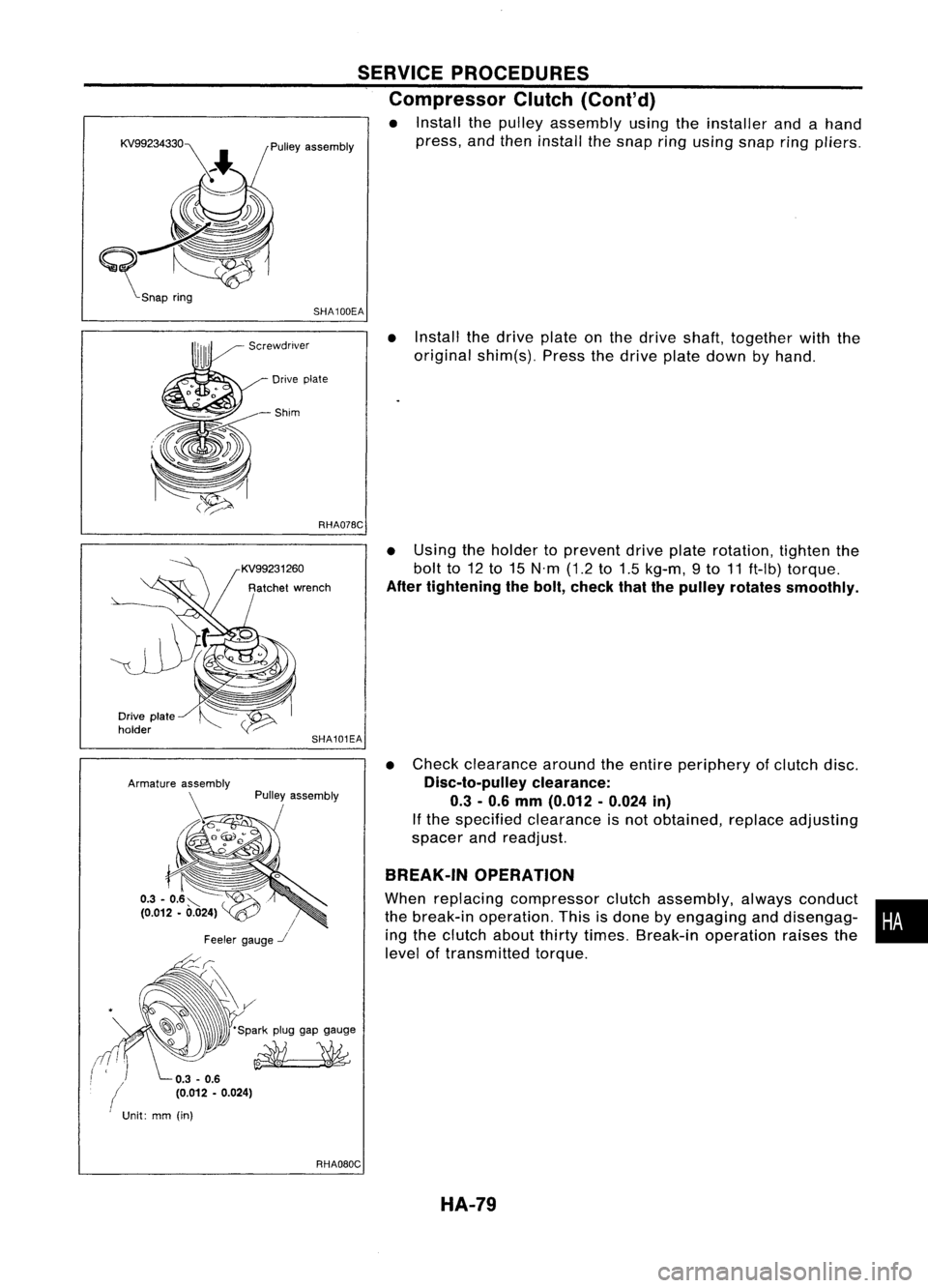
• Install thepulley assembly usingtheinstaller andahand
press, andthen install thesnap ringusing snapring
pliers.
SHA100EA
•Install thedrive plateonthe drive shaft, together withthe
original shim(s). Pressthedrive platedown byhand.
Drive plate
-Shim
RHA07BC
•Using theholder toprevent driveplaterotation, tightenthe
bolt to12to15 N'm (1.2to1.5 kg-m, 9to 11ft-Ib) torque.
After tightening thebolt, check thatthepulley rotates smoothly.
• Check clearance aroundtheentire periphery ofclutch disc.
Disc-to-pulley clearance:
0.3 -0.6 mm (0.012 -0.024 in)
If the specified clearance isnot obtained, replaceadjusting
spacer andreadjust.
BREAK-IN OPERATION
When replacing compressor clutchassembly, alwaysconduct •
the break-in operation. Thisisdone byengaging anddisengag-
i
ing the clutch aboutthirtytimes. Break-in operation raisesthe
level oftransmitted torque.
SHA101EA
Pulley assembly
/
Feeler gauge
-.I
-~~ 'Sparkpluggapgauge
~
Drive
plate
holder
(
Unit:mm(in)
RHAOBOCHA-79
Page 1484 of 1701
KV99106800
~ RHA321EA
~
s~
~ Clutchdisc
SERVICE
PROCEDURES
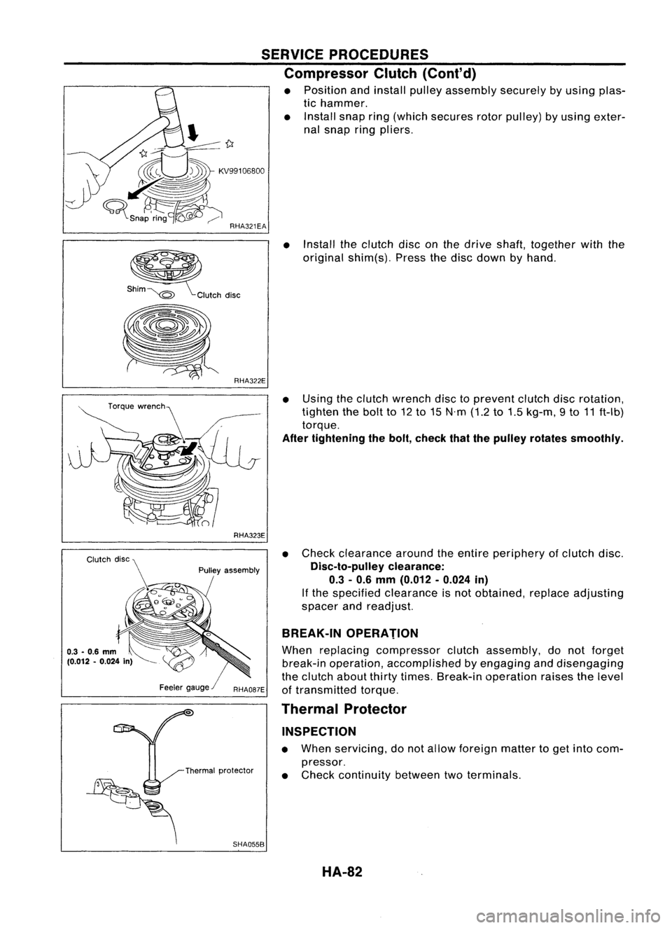
Compressor Clutch(Cont'd)
• Position andinstall pulleyassembly securelybyusing plas-
tic hammer.
• Install snapring(which secures rotorpulley) byusing exter-
nal snap ringpliers.
• Install theclutch disconthe drive shaft, together withthe
original shim(s). Pressthedisc down byhand.
RHA323E
Pulley assembly
SHA055B
•
Using theclutch wrench disctoprevent clutchdiscrotation,
tighten thebolt to12 to15 N'm (1.2to1.5 kg-m, 9to 11ft-Ib)
torque.
After tightening thebolt, check thatthepulley rotates smoothly.
• Check clearance aroundtheentire periphery ofclutch disc.
Disc-to-pulley clearance:
0.3 -0.6 mm (0.012 -0.024 in)
If the specified clearance isnot obtained, replaceadjusting
spacer andreadjust.
BREAK-IN OPERATION
When replacing compressor clutchassembly, donot forget
break-in operation, accomplished byengaging anddisengaging
the clutch aboutthirtytimes. Break-in operation raisesthelevel
of transmitted torque.
Thermal Protector
INSPECTION
• When servicing, donot allow foreign mattertoget into com-
pressor.
• Check continuity betweentwoterminals.
HA-82