1995 NISSAN ALMERA N15 torque
[x] Cancel search: torquePage 1314 of 1701
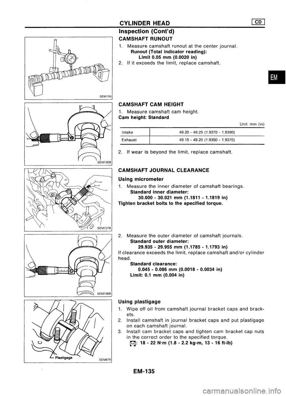
CAMSHAFTCAMHEIGHT
1. Measure camshaft camheight.
Cam height: Standard
Using micrometer
1. Measure theinner diameter ofcamshaft bearings.
Standard innerdiameter:
30.000 -30.021 mm(1.1811 -1.1819 in)
Tighten bracketboltstothe specified torque.
2. Measure theouter diameter ofcamshaft journals.
Standard outerdiameter:
29.935 -29.955 mm(1.1785 -1.1793 in)
If clearance exceedsthelimit, replace camshaft and/orcylinder
head.
Standard clearance:
0.045 -0.086 mm(0.0018 -0.0034 in)
Limit: 0.1mm (0.004 in)
•
Unit: mm(in)
49.20 -4925 (1.9370 -1.9390)
49.15 -49.20 (1.9350 -1.9370)
Intake
Exhaust
2. Ifwear isbeyond thelimit, replace camshaft.
CYLINDER
HEAD
Inspection (Cont'd)
CAMSHAFT RUNOUT
1. Measure camshaft runoutatthe center journal.
Runout (Totalindicator reading):
Limit 0.05mm(0.0020 in)
2. Ifitexceeds thelimit, replace camshaft.
CAMSHAFT JOURNALCLEARANCE
Using plastigage
1. Wipe offoilfrom camshaft journalbracket capsandbrack-
ets.
2. Install camshaft injournal bracket capsandputplastigage
on each camshaft journal.
3. Install cambracket capsandtighten cambracket capnuts
in the correct ordertothe specified torque.
~: 18-22 N'm (1.8-2.2 kg-m, 13-16 ft-Ib)
EM-135
Page 1315 of 1701
![NISSAN ALMERA N15 1995 Service Manual SEM202
SEM731BA
Grade number
Tightening sequence
r
1
@@
~.~.~
o
,..0
W
@
@ @
Facing frontofengine
(position 2)
SEM528DCYLINDER
HEAD
[£Q]
Inspection {Cont'd)
4. Remove cambracket capsan NISSAN ALMERA N15 1995 Service Manual SEM202
SEM731BA
Grade number
Tightening sequence
r
1
@@
~.~.~
o
,..0
W
@
@ @
Facing frontofengine
(position 2)
SEM528DCYLINDER
HEAD
[£Q]
Inspection {Cont'd)
4. Remove cambracket capsan](/manual-img/5/57349/w960_57349-1314.png)
SEM202
SEM731BA
Grade number
Tightening sequence
r
1
@@
~.~.~
o
,..0
W
@
@ @
Facing frontofengine
(position 2)
SEM528DCYLINDER
HEAD
[£Q]
Inspection {Cont'd)
4. Remove cambracket capsandmeasure maximum widthof
plastigage. Camshaft bearingclearance:
Limit
0.1 mm (0.004 in)
5. Ifclearance appearstoexceed thelimit, replace camshaft
or cylinder head.
• Which partstobe replaced shouldbedecided uponafter
measuring thediameters ofthe parts concerned.
Assembly
1. Install valvecomponent parts.
Install valvespring withitsnarrow pitchsidetoward cylinder
head side.
• Always installnewvalve oilseals.
Refer tooil seal replacement.
• Before installing oilseal, install valve-spring seat.
• When installing valve,applyengine oilonthe valve stem
and lipofvalve oilseal.
• Check whether thevalve faceisfree from foreign matter.
• Install valvespring retainers onthe intake sideandvalve
rotators onthe exhaust side.
• Valve rotators cannotbedisassembled.
2. Install camshaft andbrackets andtighten bracket nutstothe
specified torqueintwo orthree stages.
Camshaft-bracket nuts:
~: 18-22 N'm (1.8-2.2 kg-m, 13-16 ft-Ib)
• Tighten bracketfromcenter tooutside.
• Apply sealant tobrackets No.1and No.5.
• When installing "brackets, setcamshaft sothat thepinof
camshaft fronthead isuppermost.
• Install newcamshaft oilseals.
Refer tooil seal replacement.
17.5 (0.689)
o
o
13.0
(0.512)
NO.1 journal bracket No.5journal bracket
Unit: mm(in)
SEM676D
EM-136
Page 1330 of 1701
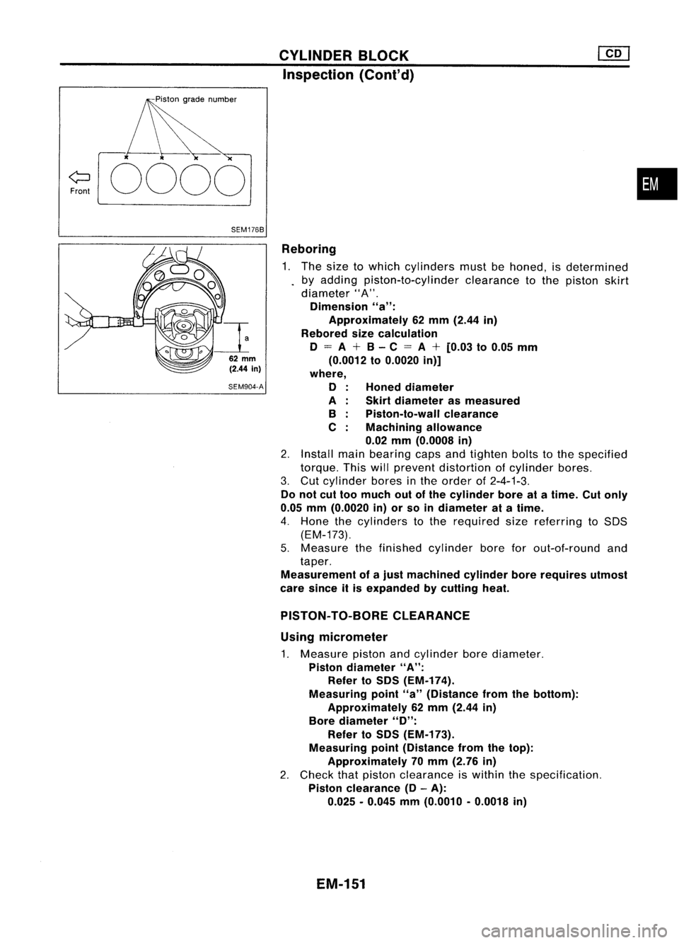
CYLINDERBLOCK
Inspection (Cont'd)
Front
0000
•
SEM1768
Reboring1. The size towhich cylinders mustbehoned, isdetermined
by adding piston-to-cylinder clearancetothe piston skirt
diameter" A".
Dimension "a":
Approximately 62mm (2.44 in)
Rebored sizecalculation
o
=
A
+
B-C
=
A
+
[0.03 to0.05 mm
(0.0012 to0.0020 in)]
where,
o
A B
C
Honed
diameter
Skirt diameter asmeasured
Piston-to-wall clearance
Machining allowance
0.02 mm(0.0008 in)
2. Install mainbearing capsandtighten boltstothe specified
torque. Thiswillprevent distortion ofcylinder bores.
3. Cut cylinder boresinthe order of2-4-1-3.
Do not cuttoo much outofthe cylinder boreatatime. Cutonly
0.05 mm(0.0020 in)orso indiameter atatime.
4. Hone thecylinders tothe required sizereferring toSOS
(EM-173).
5. Measure thefinished cylinder boreforout-of-round and
taper.
Measurement ofajust machined cylinderborerequires utmost
care since itis expanded bycutting heat.
62
mm
(2.44
in)
SEM904-A
PISTON-TO-BORE CLEARANCE
Using micrometer
1. Measure pistonandcylinder borediameter.
Piston diameter "A":
Refer toSDS (EM-174).
Measuring point"a"(Distance fromthebottom):
Approximately 62mm (2.44 in)
Bore diameter
"0":
Refer toSDS (EM-173).
Measuring point(Distance fromthetop):
Approximately 70mm (2.76 in)
2. Check thatpiston clearance iswithin thespecification.
Piston clearance
(0-
A):
0.025 -0.045 mm(0.0010 -0.0018 in)
EM-151
Page 1355 of 1701
GENERALINFORMATION •
SECTION
G
I
CONTENTS
PRECAUTIONS 2
Supplemental RestraintSystem(SRS)"AIR
BAG" (DualAirBag System) 2
Supplemental RestraintSystem(SRS)"AIR
BAG" (Single AirBag System) 2
Precautions forNATS V2.0(ForGasoline
Engine Model) 3
General Precautions 3
Precautions forMultiport FuelInjection
System orECCS Engine 5
Precautions forThree WayCatalyst 5
Engine Oils 5
Precautions forFuel 6
HOW TOUSE THIS
MANUAL 7
HOW TOREAD WIRING DIAGRAMS 9
Sample/Wiring Diagram-EXAMPL - 9
Description 11
Wiring Diagram Codes(CellCodes) 17
HOW TOPERFORM EFFICIENT DIAGNOSIS FOR
AN ELECTRICAL INCIDENT 18
Work Flow 18
Incident Simulation Tests 19
Circuit Inspection 23
HOW
TOFOLLOW FLOWCHART INTROUBLE
DIAGNOSES 29
CONSULT CHECKING SYSTEM
32
Function andSystem Application 32
Lithium BatteryReplacement.. 32
Checking Equipment 32
IDENTIFICATION INFORMATION 33
Model Variation 33
Identification Number 36
Di mens ions 39
Wheels andTires 39
LIFTING POINTSANDTOW TRUCK TOWING ..40
Preparation 40
Board-on
Lift
40
Garage JackandSafety Stand 41
2-pole Lift 42
Tow Truck Towing 43
TIGHTENING TORQUEOFSTANDARD BOLTS
44
SAE J1930 TERMINOLOGY LIST 45
SAE J1930 Terminology List.. 45
Page 1361 of 1701
HOWTOUSE THIS MANUAL
•
•
•
•
•
•
ALPHABETICAL
INDEXisprovided atthe end ofthis manual sothat youcan rapidly findtheitem •
and page youaresearching for.
A QUICK REFERENCE INDEX,ablack tab(e.g.
I=J;J)
is provided onthe first page. Youcanquickly
find thefirst page ofeach section bymating itto the section's blacktab.
THE CONTENTS arelisted onthe first page ofeach section .
THE TITLE isindicated onthe upper portion ofeach pageandshows thepart orsystem .
THE PAGE NUMBER ofeach section consists oftwo letters whichdesignate theparticular section
and anumber (e.g."BR-5").
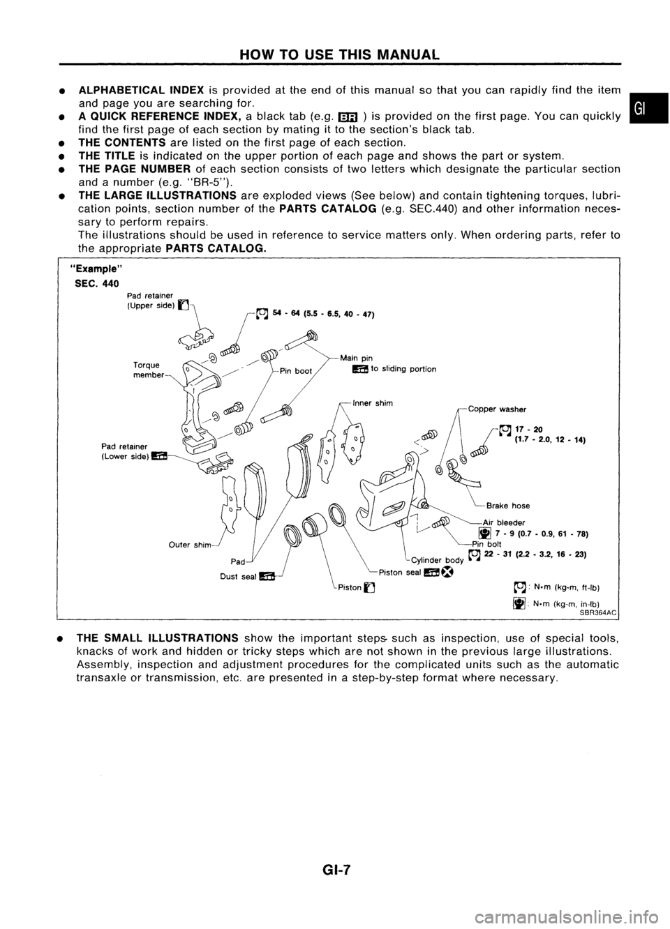
THE LARGE ILLUSTRATIONS areexploded views(Seebelow) andcontain tightening torques,lubri-
cation points, section number ofthe PARTS CATALOG (e.g.SEC.440) andother information neces-
sary toperform repairs.
The illustrations shouldbeused inreference toservice matters only.When ordering parts,referto
the appropriate PARTSCATALOG.
"Example"
SEC. 440
~~Copper washer
~ /~17-20
<~ ~~
(1.7-2.0, 12•14)
,~
'(~
,
i"::
I
cftJ ~
Brake hose
~ ~Air bleeder
V
1111
7•9 (0.7 -0.9, 61-78)
Pin bolt
~ 22-31 (2.2 -3.2, 16•23)
-Cylinder body~-~
Piston sealm~
Piston
I] ~:
N.m(kg-m, ft-Ib)
It].
N'm(kg-m, in-Ib)
SBR364AC
Outer
shim
Torque
member
Pad
retainer
(Upper side)
1]\
~ jL"J
54... 1'5•'.5, 40•
'71
/~ ~D Mainpin
/ mtosliding portion
o ~
D
~ ~
----------
Pad retainer ~
(Lower Side)m~
• THE SMALL ILLUSTRATIONS showtheimportant steps-suchasinspection, useofspecial tools,
knacks ofwork andhidden ortricky stepswhich arenotshown inthe previous largeillustrations.
Assembly, inspectionandadjustment procedures forthe complicated unitssuchasthe automatic
transaxle ortransmission, etc.arepresented inastep-by-step formatwherenecessary.
GI-7
Page 1362 of 1701
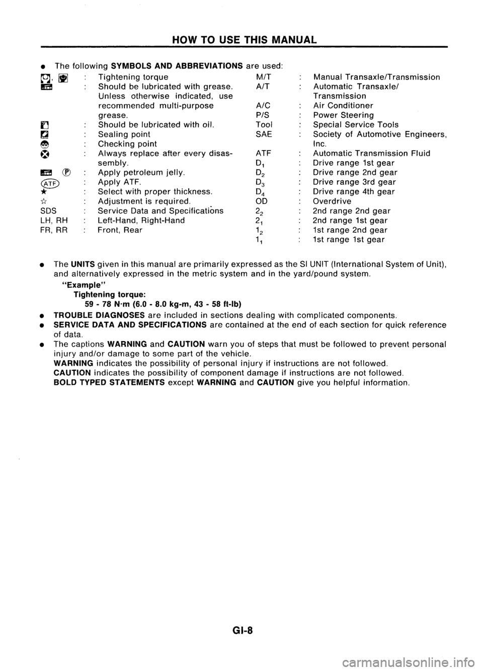
HOWTOUSE THIS MANUAL
ManualTransaxle/Transmission
Automatic Transaxle/
Transmission
Air Conditioner
Power Steering
Special Service Tools
Society ofAutomotive Engineers,
Inc.
Automatic Transmission Fluid
Drive range 1stgear
Drive range 2ndgear
Drive range 3rdgear
Drive range 4thgear
Overdrive
2nd range 2ndgear
2nd range 1stgear
1st range 2ndgear
1st range 1stgear
A/C
PIS
Tool SAE
ATF
0
1
O
2
0
3
0
4
00
2
2
2
1
1
2
1
1
•
The following
SYMBOLS ANDABBREVIATIONS
areused:
to;J,
l\tI
Tightening torque M/T
IE!
Shouldbelubricated withgrease. A/T
Unless otherwise indicated,use
recommended multi-purpose
grease.
Should belubricated withoil.
Sealing point
Checking point
Always replaceafterevery disas-
sembly.
Apply petroleum jelly.
Apply ATF.
Select withproper thickness.
Adjustment isrequired.
Service DataandSpecifications
Left-Hand, Right-Hand
Front, Rear
IE!
~
@
*
1I
SDS LH, RH
FR, RR
• The
UNITS
giveninthis manual areprimarily expressed asthe SlUNIT (International SystemofUnit),
and alternatively expressedinthe metric system andinthe yard/pound system.
"Example" Tightening torque:
59 -78 N'm (6.0-8.0 kg-m, 43-58 ft-Ib)
• TROUBLE DIAGNOSES
areincluded insections dealingwithcomplicated components.
• SERVICE DATAANDSPECIFICATIONS
arecontained atthe end ofeach section forquick reference
of data.
• The captions
WARNING
and
CAUTION
warnyouofsteps thatmust befollowed toprevent personal
injury and/or damage tosome partofthe vehicle.
WARNING
indicatesthepossibility ofpersonal injuryifinstructions arenotfollowed.
CAUTION
indicatesthepossibility ofcomponent damageifinstructions arenotfollowed.
BOLD TYPED STATEMENTS
except
WARNING
and
CAUTION
giveyouhelpful information.
GI-8
Page 1371 of 1701
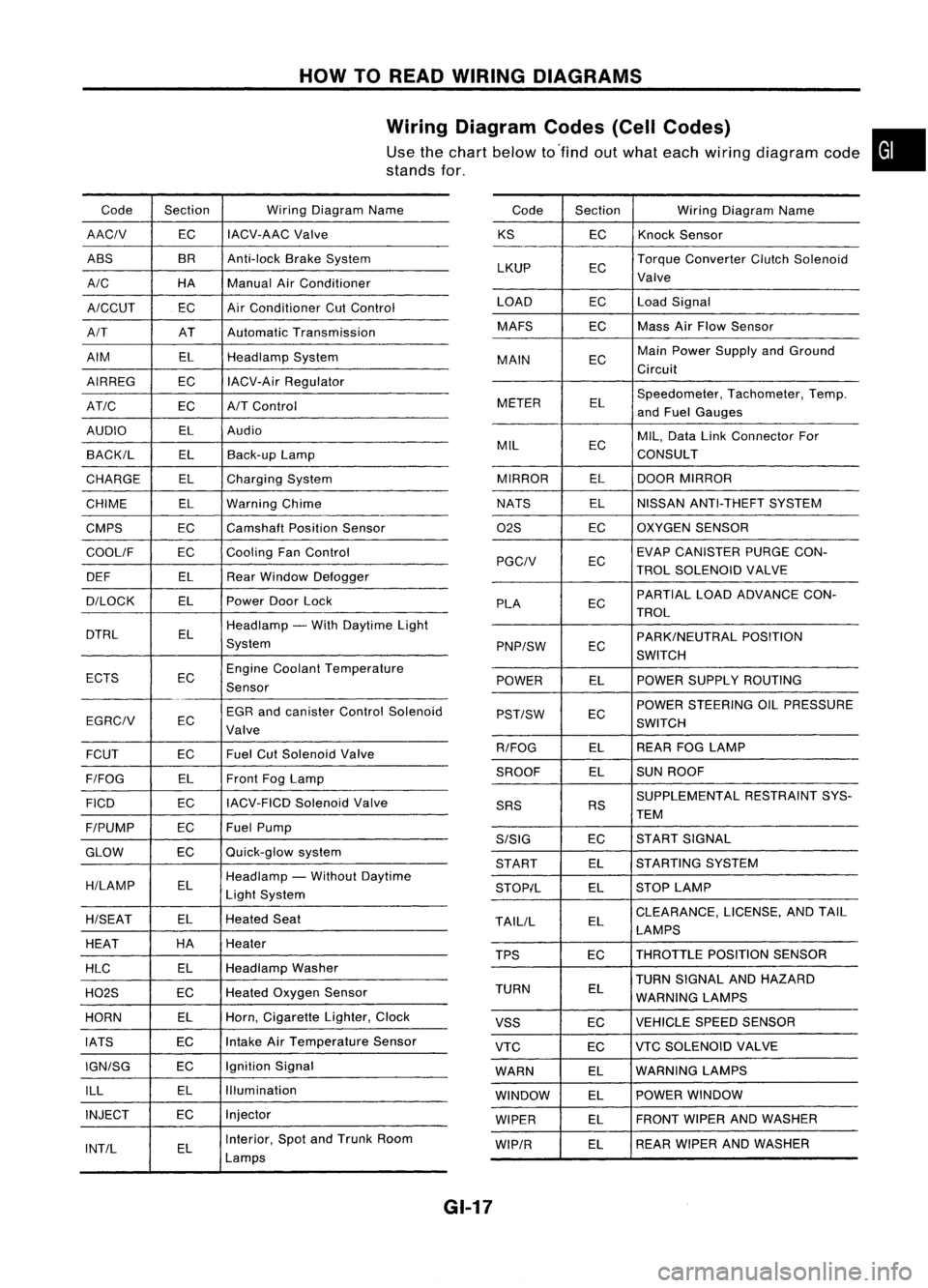
HOWTOREAD WIRING DIAGRAMS
Wiring Diagram Codes(CellCodes)
Use thechart below to'find outwhat each wiring diagram code•
stands for,
Code Section WiringDiagram Name
AACIV ECIACV-AAC
Valve
ABS BR
Anti-lock BrakeSystem
A/C HAManualAirConditioner
A/CCUT ECAir
Conditioner CutControl
A/T ATAutomatic Transmission
AIM ELHeadlamp System
AIRREG ECIACV-Air Regulator
AT/C ECA/TControl
AUDIO ELAudio
BACK/L ELBack-up Lamp
CHARGE ELCharging System
CHIME ELWarning Chime
CMPS EC
Camshaft PositionSensor
COOllF ECCooling
FanControl
DEF ELRearWindow Defogger
D/LOCK ELPowerDoorLock
DTRL ELHeadlamp
-With Daytime Light
System
ECTS ECEngine
Coolant Temperature
Sensor
EGR andcanister ControlSolenoid
EGRCIV EC
Valve
FCUT ECFuel
CutSolenoid Valve
F/FOG ELFront
FogLamp
FICO ECIACV-FICD
SolenoidValve
F/PUMP ECFuel
Pump
GLOW ECQuick-glow
system
H/LAMP ELHeadlamp
-Without Daytime
Light System
H/SEAT ELHeated
Seat
HEAT HA
Heater
HLC ELHeadlamp
Washer
H02S ECHeated
Oxygen Sensor
HORN ELHorn,
Cigarette Lighter,Clock
IATS ECIntake
AirTemperature Sensor
IGN/SG ECIgnition
Signal
ILL ELIllumination
INJECT ECInjector
INT/L ELInterior,
SpotandTrunk Room
Lamps Code
Section WiringDiagram Name
KS ECKnock
Sensor
LKUP ECTorque
Converter ClutchSolenoid
Valve
LOAD ECLoadSignal
MAFS ECMass
AirFlow Sensor
MAIN ECMain
Power Supply andGround
Circuit
METER ELSpeedometer,
Tachometer,Temp.
and Fuel Gauges
MIL ECMIL,
Data LinkConnector For
CONSULT
MIRROR ELDOOR
MIRROR
NATS ELNISSAN
ANTI-THEFT SYSTEM
02S ECOXYGEN
SENSOR
EC EVAP
CANISTER PURGECON-
PGCIV TROLSOLENOID VALVE
PLA ECPARTIAL
LOADADVANCE CON-
TROL
EC PARK/NEUTRAL
POSITION
PNP/SW SWITCH
POWER ELPOWER
SUPPLY ROUTING
POWER STEERING OILPRESSURE
PST/SW EC
SWITCH
R/FOG ELREAR
FOGLAMP
SROOF ELSUN
ROOF
SUPPLEMENTAL RESTRAINTSYS-
SRS RS
TEM
S/SIG ECST
ART SIGNAL
START ELSTARTING
SYSTEM
STOP/L ELSTOP
LAMP
TAllIL ELCLEARANCE,
LICENSE,ANDTAIL
LAMPS
TPS ECTHROTTLE
POSITIONSENSOR
TURN SIGNAL ANDHAZARD
TURN EL
WARNING LAMPS
VSS ECVEHICLE
SPEEDSENSOR
VTC ECVTC
SOLENOID VALVE
WARN ELWARNING
LAMPS
WINDOW ELPOWER
WINDOW
WIPER ELFRONT
WIPERANDWASHER
WIP/R ELREAR
WIPER ANDWASHER
GI-17
Page 1398 of 1701
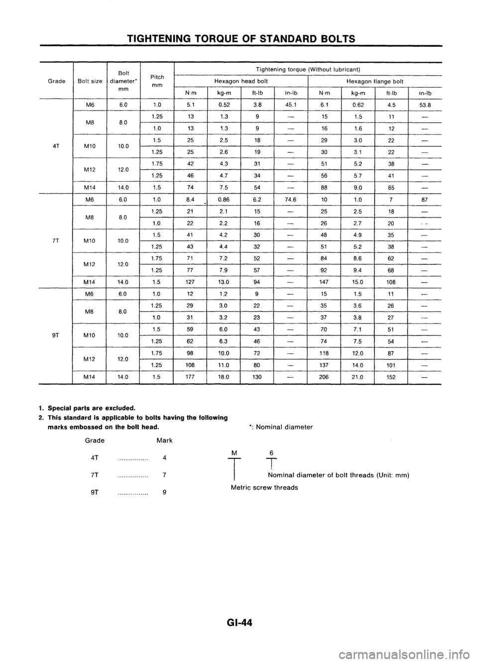
TIGHTENINGTORQUEOFSTANDARD BOLTS
Bolt Tightening
torque(Without lubricant)
Pitch
Grade Boltsize diameter' Hexagonheadbolt
Hexagonflangebolt
mm
mm
N'mkg-m
ft-Ibin-Ib
N'mkg-m
ft-Ib
in-Ib
M6 6.0 1.05.1
0.52 3.845.1 6.10.62
4.553.8
1.25 131.3
9
-
15
1.5 11
-
M8 8.0
1.0 131.3
9
-
16
1.6
12
-
1.5 252.5
18
-
293.0
22
-
4T M10 10.0
1.25 252.6
19
-
303.1
22
-
1.75 424.3
31
-
515.2
38
-
M12 12.0
1.25 464.7 34
-
5657 41
-
M14 14.0
1.574
7.5
54
-
889.0
65
-
M6 6.0
1.08.40.86 6.274.6 101.0
787
.
1.25 21
2.1 15
-
252.5 18
-
M8 80
1.0 22
2.2
16
-
262.7 20
.
-
1.5 41
4.2
30
-
484.9
35
-
7T M10 10.0
1.25 434.4
32
-
515.2
38
-
1.75 71
7.2
52
-
84
8.6 62
-
M12 12.0
1.25 777.9
57
-
929.4
68
-
M14 14.0 1.5127
13.0 94
-
147
15.0 108
-
M6 6.0
1.0 12
1.2
9
-
15
1.5 11
-
1.25 293.0
22
-
353.6
26
-
M8 8.0
1.0 313.2
23
-
37
3.8 27
--
1.5 596.0 43
-
70
7.1 51
-
9T M10 10.0
1.25 626.3
46
-
74
7.5 54
-
1.75 9810.0 72
-
118
12.0
87
-
M12 12.0
1.25 10811.0
80
-
137
14.0
101
-
M14 14.0
1.5177
18.0
130
-
206 21.0
152
-
1. Special parisareexcluded.
2. This slandard isapplicable 10bolls having thefollowing
marks embossed onthe boll head. *:
Nominal diameter
Grade
4T
7T
Mark
4
7 M
T
6
T
Nominal diameter ofbolt threads (Unit:mm)
9T 9
Metric
screwthreads
GI-44