Page 742 of 1701

ENGINEANDEMISSION BASICCONTROL SYSTEMDESCRIPTION
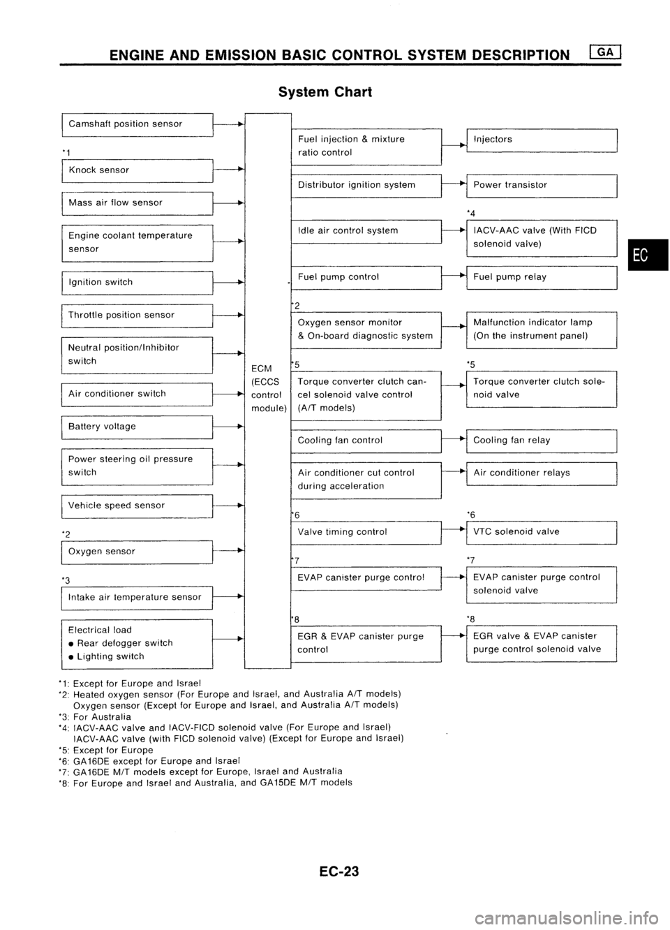
System Chart
I
Camshaft positionsensor
'1
Fuel
injection
&
mixture
ratio control Injectors
Knock sensor
Distributorignitionsystem Powertransistor
Mass airflow sensor
Engine coolant temperature
sensor
Ignition switch Idle
aircontrol system
Fuel pump control
*4
IACV-AAC valve(WithFICD
solenoid valve)
Fuel pump relay
•
'5
Throttle
positionsensor
Neutral positionllnhibitor
switch
Air conditioner switch ECM
(ECCS
control
module)
2
Oxygen sensormonitor
&
On-board diagnostic system
5
Torque converter clutchcan-
cel solenoid valvecontrol
(A/T models) Malfunction
indicatorlamp
(On theinstrument panel)
Torque converter clutchsole-
noid valve
VTC solenoid valve
*6
Air
conditioner relays
Cooling
fanrelay
EVAP canister purgecontrol
solenoid valve
Cooling
fancontrol
Air conditioner cutcontrol
during acceleration
Valve timing control
EVAP canister purgecontrol
7
6
Power
steering oilpressure
switch Battery
voltage
Intake airtemperature sensor
*3
I
Vehicle speedsensor
*2
I
Oxygen sensor
8
'8
Electrical load
• Rear defogger switch
• Lighting switch EGR
&
EVAP canister purge
control EGR
valve
&
EVAP canister
purge control solenoid valve
*1: Except forEurope andIsrael
*2: Heated oxygen sensor(ForEurope andIsrael, andAustralia A/Tmodels)
Oxygen sensor(Except forEurope andIsrael, andAustralia A/Tmodels)
*3: For Australia
*4: IACV-AAC valveandIACV-FICD solenoidvalve(ForEurope andIsrael)
IACV-AAC valve(withFICDsolenoid valve)(Except forEurope andIsrael)
'5: Except forEurope
*6: GA16DE exceptforEurope andIsrael
*7: GA16DE MITmodels exceptforEurope, IsraelandAustralia
*8: For Europe andIsrael andAustralia, andGA15DE MITmodels
EC-23
Page 752 of 1701

BASICSERVICE PROCEDURE
• FUEL PRESRELEASE. D
FUEL PUMP WILLSTOP BY
TOUCHING STARTDURING
IDLE.
CRANK AFEW TIMES AFTER
ENGINE STALL
---S-T~-RT--
SEF823K
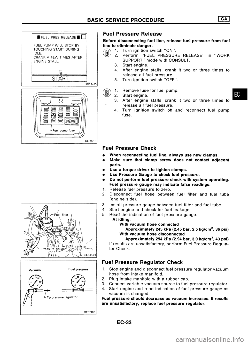
Fuel
Pressure Release
Before disconnecting fuelline, release fuelpressure fromfuel
line toeliminate danger.
(ij\
1.Turn ignition switch"ON".
~ 2.Perform "FUELPRESSURE RELEASE"in"WORK
SUPPORT" modewithCONSULT.
3. Start engine.
4. After engine stalls,crankittwo orthree times to
release allfuel pressure.
5. Turn ignition switch"OFF".
SEF921P
00
~:
3.
4.
Remove
fuseforfuel pump. •
Start engine.
After engine stalls,crankittwo orthree times to
release allfuel pressure.
Turn ignition switchoffand reconnect fuelpump
fuse.
Vacuum Fuelpressure
..... L
To pressure regulator
Fuel
Pressure Check
• When reconnecting fuelline, always usenew clamps.
• Make surethatclamp screwdoesnotcontact adjacent
parts.
• Use atorque drivertotighten clamps.
• Use Pressure Gaugetocheck fuelpressure.
• Donot perform fuelpressure checkwithsystem operating.
Fuel pressure gaugemayindicate falsereadings.
1. Release fuelpressure tozero.
2. Disconnect fuelhose between fuelfilter andfuel tube
(engine side).
3. Install pressure gaugebetween fuelfilter andfuel tube.
4. Start engine andcheck forfuel leakage.
5. Read theindication offuel pressure gauge.
At idling:
With vacuum hoseconnected
Approximately 245kPa (2.45 bar,2.5kg/cm
2,
36psi)
With vacuum hosedisconnected
Approximately 294kPa (2.94 bar,3.0kg/cm
2,
43psi)
If results areunsatisfactory, performFuelPressure Regula-
tor Check.
Fuel Pressure Regulator Check
1. Stop engine anddisconnect fuelpressure regulator vacuum
hose fromintake manifold.
2. Plug intake manifold witharubber cap.
3. Connect variablevacuumsourcetofuel pressure regulator.
4. Start engine andread indication offuel pressure gaugeas
vacuum ischanged.
Fuel pressure shoulddecrease asvacuum increases. Ifresults
are unsatisfactory, replacefuelpressure regulator.
SEF7188
EC-33
Page 787 of 1701

TROUBLEDIAGNOSIS -General Description
*
MONITOR
*
NO FAIL
ENG TEMP SEN 80°C
RECORD
Cam follower
lever
o
SEF214N
SEF147N Fast
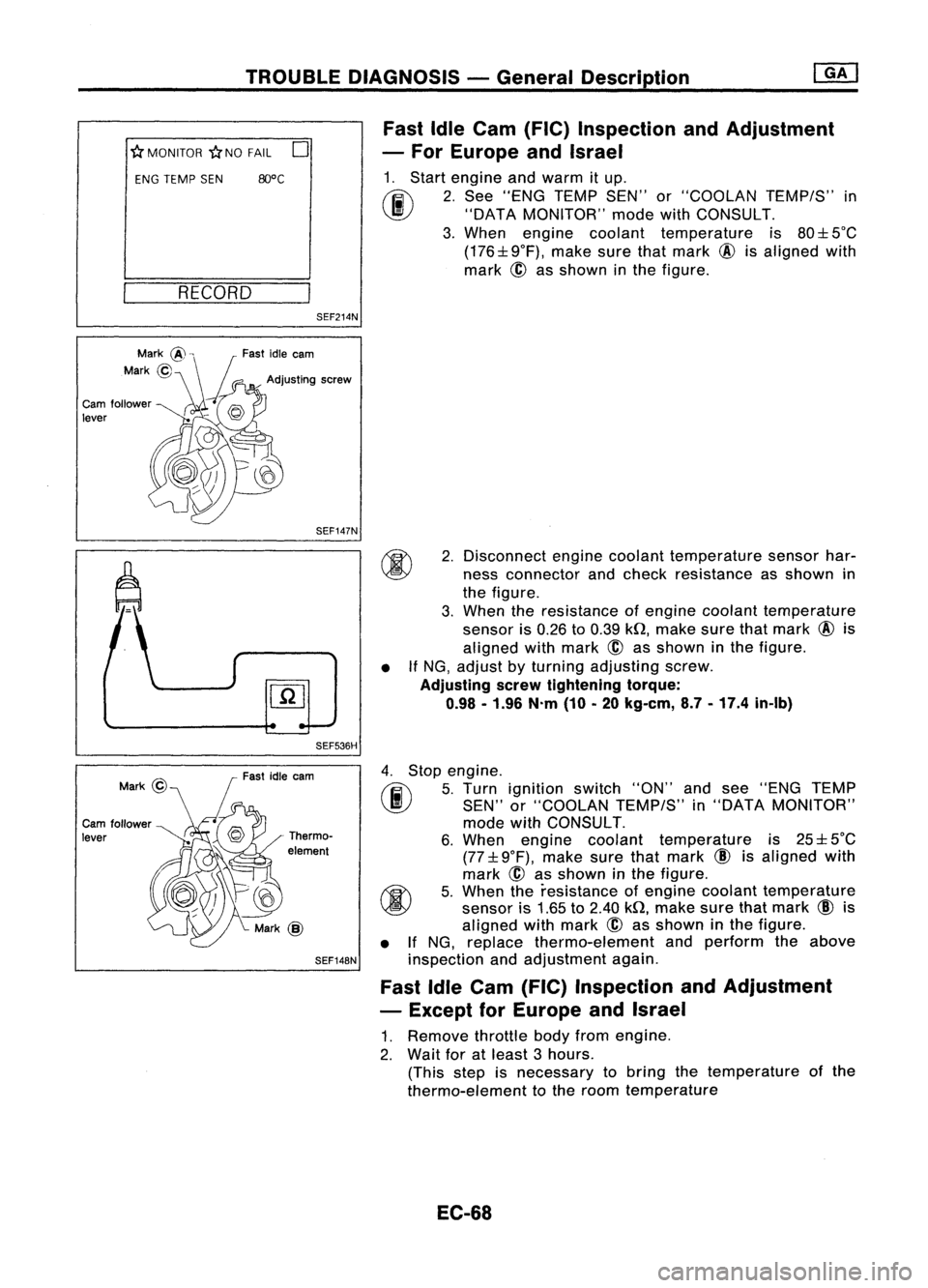
IdleCam (FIC) Inspection andAdjustment
- For Europe andIsrael
1. Start engine andwarm itup.
(ij\
2.See "ENG TEMP SEN"or"COOLAN TEMP/S"in
~ "DATAMONITOR" modewithCONSULT.
3. When engine coolant temperature is80:l: 5°C
(176:l:9°F), makesurethatmark @isaligned with
mark ~asshown inthe figure.
SEF536H •
2.
Disconnect enginecoolant temperature sensorhar-
ness connector andcheck resistance asshown in
the figure.
3. When theresistance ofengine coolant temperature
sensor is0.26 to0.39 kQ,make surethatmark @is
aligned withmark
@
asshown inthe figure.
If NG, adjust byturning adjusting screw.
Adjusting serewtightening torque:
0.98 -1.96 N.m(10-20 kg-em, 8.7-17.4 in-Ib)
Cam follower
lever Fast
idleearn
Thermo-
element
SEF148N
4.
Stop engine.
rF.i\
5.Turn ignition switch"ON"andsee "ENG TEMP
~ SEN"or"COOLAN TEMP/S"in"DATA MONITOR"
mode withCONSULT.
6. When engine coolant temperature is25:l: 5°C
(77:l: 9°F), make surethatmark
CID
isaligned with
mark @asshown inthe figure.
~ 5.When theresistance ofengine coolant temperature
~ sensoris1.65 to2.40 kQ,make surethatmark
CID
is
aligned withmark
@
asshown inthe figure.
• IfNG, replace thermo-element andperform theabove
inspection andadjustment again.
Fast IdleCam (FIC) Inspection andAdjustment
- Except forEurope andIsrael
1. Remove throttlebodyfromengine.
2. Wait foratleast 3hours.
(This stepisnecessary tobring thetemperature ofthe
thermo-element tothe room temperature
EC-68
Page 799 of 1701

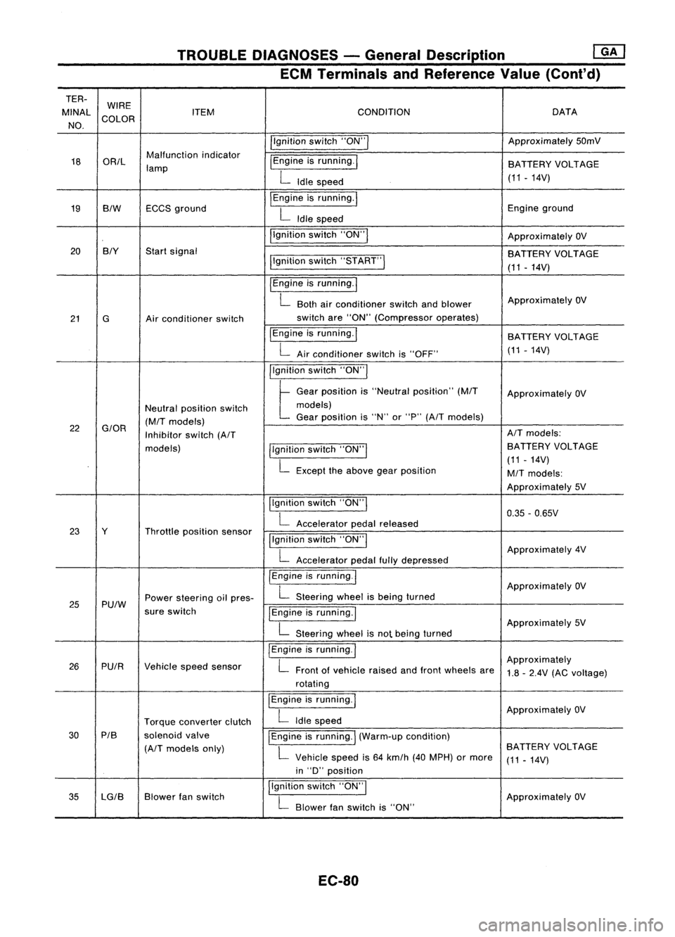
TROUBLEDIAGNOSES -General Description ~
ECM Terminals andReference Value(Cont'd)
TER- WIRE
MINAl ITEM CONDITION DATA
NO. COLOR
/'gnitionswitch"ON'" Approximately
50mV
18 OR/l Malfunction
indicator
I
Engine isrunning.
I
lamp BATTERY
VOLTAGE
L
Idle speed (11.14V)
19 BIW ECCS
ground
I
Engine isrunning.
I
Engineground
L
Idle speed
I'gnition switch"ON"
I
ApproximatelyOV
20 BIY
Startsignal
BATTERYVOLTAGE
I'gnition switch"5TART"
I
(11-14V)
I
Engine isrunning.
I
L
Both airconditioner switchandblower Approximately
OV
21 G Airconditioner switch switch
are"ON" (Compressor operates)
IEngine isrunning.
I
BATTERYVOLTAGE
L
Airconditioner switchis"OFF" (11
-14V)
I'gnition switch"ON'"
t
Ge.,
po,"'on "
"Ne"".1
po,ltlon"
(MIT
Approximately OV
Neutral position switch models)
(M/T
models) Gear
position is"N" or"P"
(A/T
models)
22
G/OR
Inhibitorswitch
(A/T AIT
models:
models) llgnitionswitch"ON'" BATTERY
VOLTAGE
L
Except theabove gearposition (11
-14V)
M/T
models:
Approximately 5V
Ilgnition switch"ON"
I
0.35-0.65V
L
Accelerator pedalreleased
23 Y Throttleposition sensor
!'gnitionswitch"ON"
I
L
Accelerator pedalfullydepressed Approximately
4V
/Engine isrunning.1
ApproximatelyOV
25 Pu/W Power
steering oilpres-
L
Steering wheelisbeing turned
sure switch
IEngineisrunning.1
L
Steering wheelisnot being turned Approximately
5V
I
Engine isrunning.
I
Approximately
26 PUIR Vehiclespeedsensor
L
Front ofvehicle raisedandfront wheels are
1.8-2.4V (ACvoltage)
rotating
I
Engine isrunning.
I
ApproximatelyOV
Torque converter clutch
L
Idle speed
30 PIB
solenoidvalve
I
Engine isrunning.
I
(Warm-up condition)
(A/T
models only)
L
Vehicle speedis64 km/h (40MPH) ormore BATTERY
VOLTAGE
(11-14V)
in "D" position
35 lG/B Blower
fanswitch I,gnition
switch"ON",
ApproximatelyOV
L
Blower fanswitch is"ON"
EC-80
Page 806 of 1701
TROUBLEDIAGNOSES -General Description
[ill
ECM Terminals andReference Value(Cont'd)
TERMINAL WIRE
ITEM CONDITION
DATA
NO. COLOR
IEngineisrunning.1
7-13V
L
Idle speed
IACV-AAC valve(Clos-
~gineisrunning.1
PU/W ing
signal: Exceptfor
Europe andIsrael)
t
Stee,'", wheel',be'",t,med
11-14V
Air conditioner isoperating.
Rear window defogger switchis"ON".
Lighting switchis"ON".
113 IEngineisrunning.1
11-14V
L
Idle speed
5B IACV-AAC
valve I~ngine
isrunning.1
(For Europe andIsrael)
~Steee'", wheel"be'", t,med
Air conditioner isoperating. 1
-10V
Rear window defogger switchis"ON".
Lighting switchis"ON".
IEngine isrunning.1
ApproximatelyOV
Torque converter clutch
L
Idle speed
solenoid valve
115 P/B
(A/T
models exceptforIEngine
isrunning
I
(Warm-up condition)
L
BATTERY
VOLTAGE
Europe andIsrael)
Vehiclespeedis60 km/h (37MPH) or
(11-14V)
more in
"0"
position.
EC-87
•
Page 918 of 1701
TROUBLEDIAGNOSIS FORNON-DETECTABLE ITEMS
Valve Timing Control (VTC)(Cont'd)
OPERATION
Engine operating condition Valve
timing control Intakevalveopening
Valveoverlap Enginetorquecurve
solenoid valve
andclosing time
• Engine coolant temperature
is 70"C (158"F) ormore .
• Engine loadishigh .
• Engine speedisbetween
ONAdvance
Increased @
1,500 rpmand5,100 rpm.
• Engine speedis6,800 rpmor
more.
Those otherthanabove OFFNormal Normal
CD
CD
Valve timing control (VTC)solenoid valveisOFF. @Valve timing control (VTC)solenoid valveisON.
•
Effr
t
f__ ~
Torque ~
L__ _
Engine speed
--+-
Except forAustralia
Exhaust valve
open time
Intake closes
For Australia
Exhaust valve
open time
intake cioses Intake
valve
open lime
BOC
CD
I~Overlap (-12°)
TOC ,Intake opens
Intake valve
open time Overlap
(18°)
@
BOC
CD
EC-199 @
SEF183R
Page 938 of 1701
TROUBLEDIAGNOSIS FORNON-DETECTABLE ITEMS
Torque Converter ClutchSolenoid Valve
IQ.61
y
I
y
1l1J1
ffi
=r
(E202)
y
I
y
r::b,
TORQUE
~3 CONVERTER
CLUTCH
SOLENOID
II 111 VALVE
=r
(E223)
PIB
I
PIS
r::b,@i)
Il4Jl
m
PIB
L
(E10!)
CHID
(M49)
CEID
PiS ~ PIS--PIS ~~ P/S"""l
PIS
Ii1N
LKUP
IGNITION
SWITCH
ON or START
10A
rn FUSE
BLOCK
(JIB)
(Ef06)
Refer
toEL-POWER.
EC-LKUP-01
-: Detectable line
for DTC
-: Non-detectable
line forDTC
ECM (ECCS
CONTROL
MODULE)
em
•
~~~~
~ S
w.g@>
S
~~
~S
Refer
tolast page
(Foldout page).
HEeD5?
EC-219
Page 939 of 1701
TROUBLEDIAGNOSIS FORNON-DETECTABLE ITEMS
em
Torque Converter ClutchSolenoid Valve(Cont'd)
GA16DE forAustralia (AIT models)
EC-LKUP-01
IGNITION SWITCH
ON
01"
START
10A
rn FUSE
BLOCK (JIB)
106)
Refel"
toEL-POWER. _.
Detectable line
fol" DTC
-: Non-detectable
line fol"DTC
U
Q
j
6
11
y
I
y
$=
y
I
y
r=!::,
TORQUE
~3 CONVERTER
CLUTCH
SOLENOID
~~E
P/B
I
P/B
r=!::,
CE201)
1C4J1~
P/B
L
~CM8)
@@
PIS ~ PIS--PIS ~~ PiS~
P/B
Ii3tiJ
LKUP ECM
(ECCS
CONTROL
MODULE)
em
~~ ~~FmB1~
lIDIDZIID
B
w.g@)
B~ B
Refer
tolast page
(Foldout page).
101 102 103
107 108 109
113
114 115 104
105106
110
111
112
116
117
118
EC-220 HEC085