Page 190 of 1701
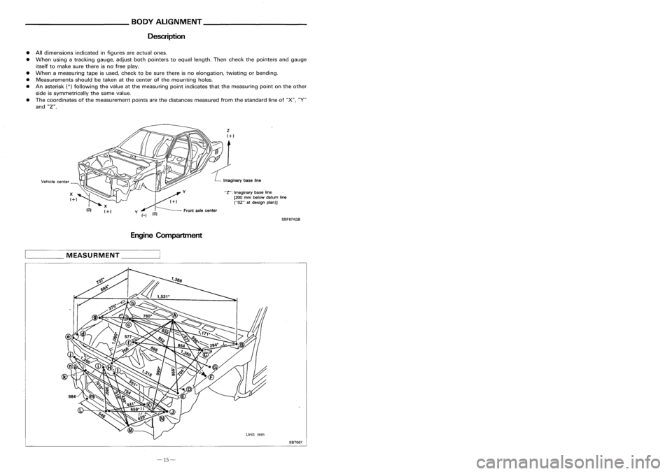
__________ BODYALIGNMENT _
_ PRECAUTIONS _
Description PrecautionsForHandling HighStrength Steel
• Alldimensions indicatedinfigures areactual ones.
• When usingatracking gauge,adjustbothpointers toequal length. Thencheck thepointers andgauge
itself tomake surethere isno free play.
• When ameasuring tapeisused, check tobe sure there isno elongation, twistingorbending.
• Measurements shouldbetaken atthe center ofthe mounting holes.
• Anasterisk
(*)
following thevalue atthe measuring pointindicates thatthemeasuring pointonthe other
side issymmetrically thesame value.
• The coordinates ofthe measurement pointsarethe distances measured fromthestandard lineof"X", "V"
and "Z".
EngineCompartment
D=2T+3(mm)
D=2T+O.12 (in)
•
The electrode tipdiameter mustbereformed
properly according tothe panels thickness.
•
The spot ungget onHSS panel isharder than
that ofan ordinary steelpanel.
Therefore, forspot cutting HSSpanel, ahigh
torque drillofalow speed (1,000 to1,200
rpm) maybeused tomaintain itsdurability
and facilitate theoperation.
• HSS panels withatensile strength of785 to981 N/mm
2
(80to100 kg/mm
2,
114to142 klb/sq in),
used asreinforcement inthe door guard barand inthe bumper, istoo high intensile strength touse
for general repairs.Whenthesepanels aredamaged, theouter panels alsosustain consequential
damage; therefore, thesepanels arenever remedied withoutreplacing thedoor assembly orbumper
assembly.
2. Precautions inspot welding
This work should beperformed understandard workconditions. However,workcontrol mustbeexercised
as folloows:
SBF8?4GB
"Z":
Imaginary baseline
[200 mmbelow datum line
("OZ" atdesign plan)]
Front axlecenter
/
y (_)
(0)
Incorrect
Incorrect
Correct
D==Tip+diameter
T
,::=T====p=la::t_e=-=-_t_h=i_C=k=_n=_e_s=s= __,-- ~
• The panel surfaces mustbefitted toeach
other, leaving nogaps.
____
MEASURMENT _
SBT08?
-15- -30-
Page 205 of 1701
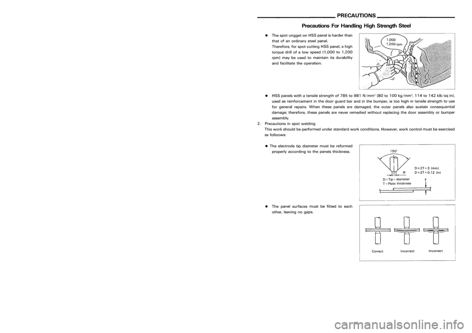
__________ BODYALIGNMENT _
_ PRECAUTIONS _
Description PrecautionsForHandling HighStrength Steel
• Alldimensions indicatedinfigures areactual ones.
• When usingatracking gauge,adjustbothpointers toequal length. Thencheck thepointers andgauge
itself tomake surethere isno free play.
• When ameasuring tapeisused, check tobe sure there isno elongation, twistingorbending.
• Measurements shouldbetaken atthe center ofthe mounting holes.
• Anasterisk
(*)
following thevalue atthe measuring pointindicates thatthemeasuring pointonthe other
side issymmetrically thesame value.
• The coordinates ofthe measurement pointsarethe distances measured fromthestandard lineof"X", "V"
and "Z".
EngineCompartment
D=2T+3(mm)
D=2T+O.12 (in)
•
The electrode tipdiameter mustbereformed
properly according tothe panels thickness.
•
The spot ungget onHSS panel isharder than
that ofan ordinary steelpanel.
Therefore, forspot cutting HSSpanel, ahigh
torque drillofalow speed (1,000 to1,200
rpm) maybeused tomaintain itsdurability
and facilitate theoperation.
• HSS panels withatensile strength of785 to981 N/mm
2
(80to100 kg/mm
2,
114to142 klb/sq in),
used asreinforcement inthe door guard barand inthe bumper, istoo high intensile strength touse
for general repairs.Whenthesepanels aredamaged, theouter panels alsosustain consequential
damage; therefore, thesepanels arenever remedied withoutreplacing thedoor assembly orbumper
assembly.
2. Precautions inspot welding
This work should beperformed understandard workconditions. However,workcontrol mustbeexercised
as folloows:
SBF8?4GB
"Z":
Imaginary baseline
[200 mmbelow datum line
("OZ" atdesign plan)]
Front axlecenter
/
y (_)
(0)
Incorrect
Incorrect
Correct
D==Tip+diameter
T
,::=T====p=la::t_e=-=-_t_h=i_C=k=_n=_e_s=s= __,-- ~
• The panel surfaces mustbefitted toeach
other, leaving nogaps.
____
MEASURMENT _
SBT08?
-15- -30-
Page 274 of 1701
GG94310000or
commercial equivalent
SBR820BA
For
tightening flarenut
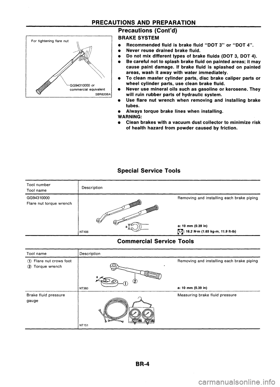
Tool number
Tool name
PRECAUTIONS
ANDPREPARATION
Precautions (Conl'd)
BRAKE SYSTEM
• Recommended fluidisbrake fluid"DOT 3"or"DOT 4".
• Never reusedrained brakefluid.
• Donot mix different typesofbrake fluids (DOT3,DOT 4).
• Becareful nottosplash brakefluidonpainted areas;itmay
cause paintdamage. Ifbrake fluidissplashed onpainted
areas, washitaway withwater immediately.
• Toclean master cylinder parts,discbrake caliper partsor
wheel cylinder parts,useclean brake fluid.
• Never usemineral oilssuch asgasoline orkerosene. They
will ruin rubber partsofhydraulic system.
• Use flare nutwrench whenremoving andinstalling brake
tubes.
• Always torquebrakelineswhen installing.
WARNING:
• Clean brakes withavacuum dustcollector tominimize risk
of health hazard frompowder causedbyfriction.
Special Service Tools
Description
GG9431 0000
Flare nuttorque wrench
NT406
Removing
andinstalling eachbrake piping
a: 10 mm (0.39 in)
~: 16.2N'm(1.65 kg-m, 11.9f1-lb)
Commercial ServiceTools
Description
Tool name
CD
Flare nutcrows foot
@ Torque wrench
Brake fluidpressure
gauge
NT360
NT151
Removing
andinstalling eachbrake piping
a: 10 mm (0.39 in)
Measuring brakefluidpressure
BR-4
Page 284 of 1701
SBR435BMASTER
CYLINDER
Assembly (Cont'd)
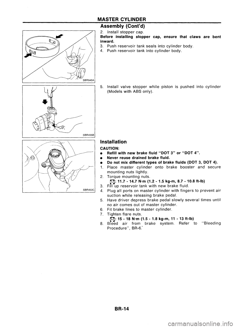
2. Install stopper cap.
Before installing stoppercap,ensure thatclaws arebent
inward.
3. Push reservoir tankseals intocylinder body.
4. Push reservoir tankintocylinder body.
5. Install valvestopper whilepiston ispushed intocylinder
(Models withABS only).
Installation
CAUTION:
• Refill withnewbrake fluid"DOT 3"or"DOT 4".
• Never reusedrained brakefluid.
• Donot mix different typesofbrake fluids(DOT3,DOT 4).
1. Place master cylinder ontobrake booster andsecure
mounting nutslightly.
2. Torque mounting nuts.
~: 11.7 -14.7 N'm(1.2-1.5 kg-m, 8.7-10.8 ft-Ib)
3. Fillupreservoir tankwith newbrake fluid.
4. Plug allports onmaster cylinder withfingers toprevent air
suction whilereleasing brakepedal.
5. Have driver depress brakepedalslowly several timesuntil
no air comes outofmaster cylinder.
6. Fitbrake linestomaster cylinder.
7. Tighten flarenuts.
~: 15-18 N'm (1.5-1.8 kg-m, 11-13 ft-Ib)
8. Bleed airfrom brake system. Referto"Bleeding
Procedure", BR-6."
BR-14
Page 290 of 1701
FRONTDISCBRAKE
m
@
tosliding portion
SEC.
440
CL22VD ANDCL22VE
t~m@
~ I
0
@~@'~I~_\ '~
'j/0
\ ~ ~m@
tOJ
22-
31
(2.2 -3.2,
16-
23)
'1r~
m'8'
(fJJ;18~
-=a
18\
iii:
N'm(kg-m, in-Ib)
\!.o/WLJ\SI
~WIlI[LJ;I\OI
(OJ :
N'm (kg-m, ft-Ib)
17
fJ@
m
@:
Rubber greasepoint
(] @ :
Brake fluidpoint
m
@:
PBC (Poly ButylCuprysil) greaseorsilicone-based greasepoint
SBR206D
CD
Main pin
@
Pinboot
@
Torque member fixingbolt
@
Torque member
@
Shim cover
@
Inner shim
(j)
Inner pad
@
Padretainer
@
Outer pad
@J
Outer shim
@
Connecting bolt
@
Copper washer
@
Main pinbolt
@
Bleed valve
@
Cylinder body
@
Piston seal
@
Piston
@
Piston boot
@
Padreturn spring
BR-20
Page 291 of 1701
FRONTDISCBRAKE
•
SBR207D
@ Main pinbolt
@ Cylinder body
@ Piston seal
@ Piston
@
Piston boot
@J
Piston bootretainer
15
~
31-41
16
-I
(3.2-4.2, 23-30)
@
Ij]
7•9 (0.7 •0.9, 61•78)
SEC.
440
AD22VF
Ij]:
N.m (kg-m, in-Ib)
to.J :
N.
m
(kg-m, 1t-lb)
m
@:
Rubber greasepoint
f] :
Brake fluidpoint
m
@:
PBC (Poly ButylCuprysil) greaseorsilicone-based greasepoint
G)
Plug @
Inner pad
@ Torque member @
Inner shim
@
Torque member fixingbolt @
Shim cover
@
Pinboot @
Connecting bolt
@
Outer shim
@
Brake hose
@
Outer pad
@
Copper washer
(J)
Padretainer
@
Airbleeder
BR-21
Page 292 of 1701
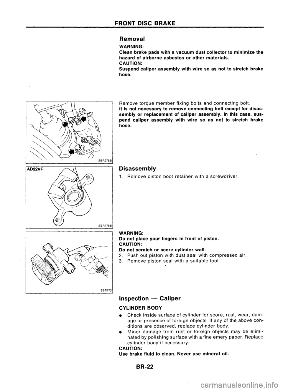
AD22VF SBR776B
SBR772 FRONT
DISCBRAKE
Removal
WARNING:
Clean brakepadswithavacuum dustcollector tominimize the
hazard ofairborne asbestos orother materials.
CAUTION:
Suspend caliperassembly withwire soasnot tostretch brake
hose.
Remove torquemember fixingboltsandconnecting bolt.
It is not necessary toremove connecting boltexcept fordisas-
sembly orreplacement ofcaliper assembly. Inthis case, sus-
pend caliper assembly withwire soas not tostretch brake
hose.
Disassembly
1. Remove pistonbootretainer withascrewdriver.
WARNING: Do not place yourfingers infront ofpiston.
CAUTION: Do not scratch orscore cylinder wall.
2. Push outpiston withdust sealwithcompressed air.
3. Remove pistonsealwith asuitable tool.
Inspection -Caliper
CYLINDER BODY
• Check insidesurface ofcylinder forscore, rust,wear, dam-
age orpresence offoreign objects. Ifany ofthe above con-
ditions areobserved, replacecylinder body.
• Minor damage fromrustorforeign objects maybeelimi-
nated bypolishing surfacewithafine emery paper.Replace
cylinder bodyifnecessary.
CAUTION: Use brake fluidtoclean. Neverusemineral oil.
BR-22
Page 300 of 1701
REARDISCBRAKE
SBR208D
Piston seal
@
@
Snap ring
@
Spacer
Wave washer
@
@l
Spacer
@
Bearing
@
Adjuster
@'J
Cup
@)
Piston
@
Piston boot
18
-22)
~ 25-29 (2.5 -3.0,
~
Cable guide
Cylinder
Toggle lever
Pin
Pin boot
ember
Torque m
Retainer
Inner shim
Inner pad
Pad retainer
Outer pad
SEC.
440
CL7HB AND
CL9HC
!
@m@to
,Ii""
pmli"
J
m
@to
p,d ,,,,,,, ""
@~~~:':'~) ~' ~
:d~CL9HC)
II-'b) •
m@
@
'f /
B)
""" .N.m (kg-m,. (ModelCL9HC) @(ModelCL7H
,-,
- "pom' .
'i'i' ,Robb" "" d""" pom'
m'O'
kfluid point eor silicone-base
in
@ :
Bra e Cuprysil)greas
U BC(Poly Butyl
m
@,
p
@
Oo'e"him
@
Strut
@
O-ring
@
Push rod
@
Keyplate
@
Snap ring
@
Seat
@
Spring
@l
Spring cover
@
Snap ring
CD
@
@
@
@
(6)
(j)
@
@
@
@
BR-30