Page 85 of 1701
Model34X69, 34X70, 34X80,34X81 REPAIR
FORCOMPONENT PARTS
Control ValveAssembly (Cant'd)
Model 34X68
Model
34X69,
34X70,
34X80,
34X81
Model
34X68
Model
34X69,
34X70,
34X80,
34X81
h,
Install support platesandtighten bolts
CID
tospecified
torque.
[j]:
3.4-4.4 N'm (0.35 -0.45 kg-m, 30.4-39.1 in-Ib)
SAT529HA
i.
Install tubeconnector andtubes tolower body,
• Install oilcircuit sideoftube connector faceup.
SAT603DB
SAT104DB
AT-8S
•
Page 89 of 1701
Unit:mm(in)
Name ofcontrol valves Length
ALength B Type
Pressure modifiervalve
Lock-up controlvalve 6.0
(0.236) 28.0(1.102)
4-2 sequence valve
Kickdown modulator valve
3-2 timing valve A
1st reducing valve 6.0
(0.236) 21.5(0.846)
Throttle modulator valve
4th speed cutvalve
1-2 accumulator valve 6.0
(0.236) 38.5(1516)
Torque converter reliefvalve 13.0(0.512) 17.0(0.669) B
SAT611D
REPAIR
FORCOMPONENT PARTS
Control ValveUpper Body(Cont'd)
Retainer plate:
Type B
A
E{1}
B
A
Type A
•Install proper retainer plates.
•
AT-89
Page 139 of 1701
~-_./-'--.~.-l
~
1I
-~------~._--~
.
• ~KV38105710
• Wooden
block
NAT060 ASSEMBLY
Assembly 1(Cont'd)
4. Install returnspring.
Adjustment 1
DIFFERENTIAL SIDEBEARING PRELOAD
-" Model 34X81-
1. Install differential sidebearing outerracewithout adjusting
shim ontransmission case.
2. Install differential sidebearing outerraceonconverter
housing.
3. Place finaldrive assembly ontransmission case. •
4. Install transmission caseonconverter housing.Tighten
transmission casefixing bolts
@
and
CID
tothe specified
torque.
5. Attach dialindicator ondifferential caseattransmission
case side.
6. Insert Toolintodifferential sidegear from converter hous-
ing.
7. Move Toolupand down andmeasure dialindicator deflec-
tion.
8. Select proper thickness ofdifferential sidebearing adjust-
ing shim(s) usingSDStable asaguide.
Differential sidebearing adjusting shim:
Refer to50S, AT-HO.
AT-139
Page 140 of 1701

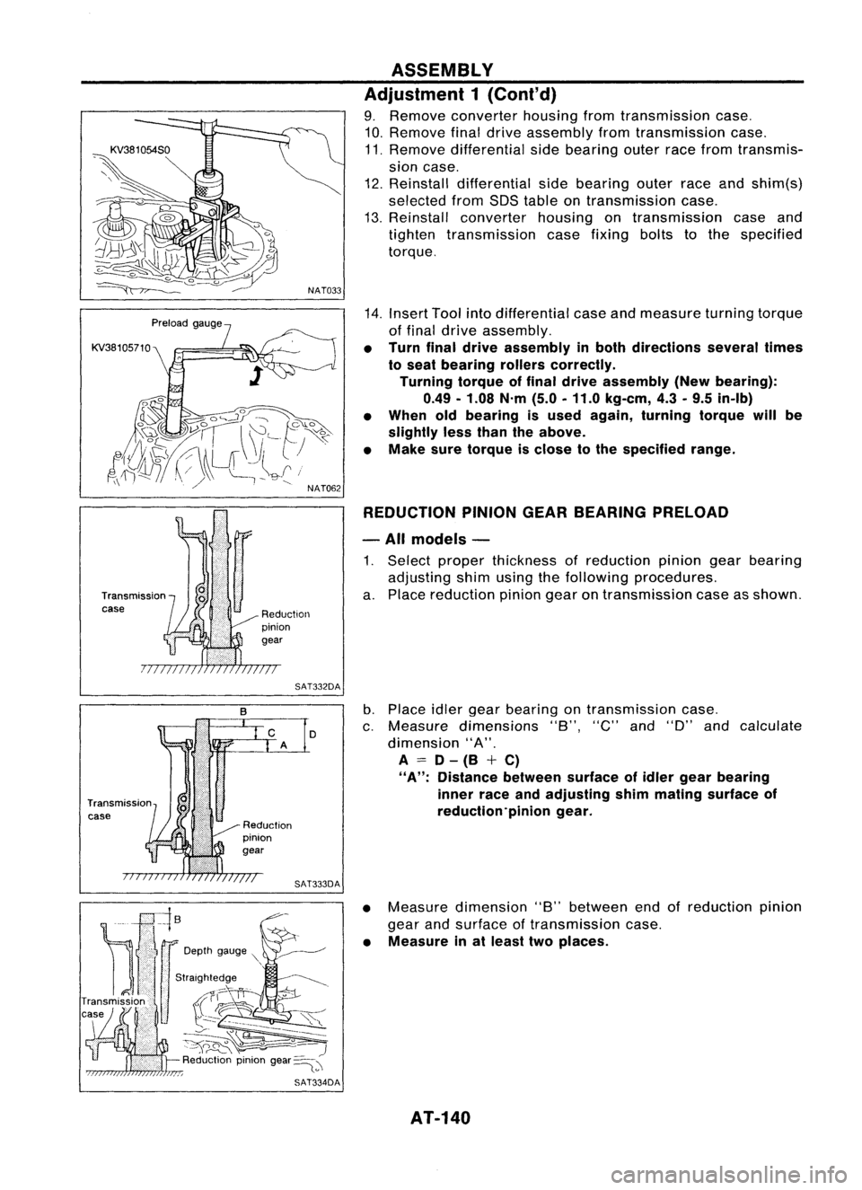
KV38105710
Transmission
case
NAT033
Reduction
pinion
gear
SAT332DA
D
SAT333DA ASSEMBLY
Adjustment 1(Cont'd)
9. Remove converter housingfromtransmission case.
10. Remove finaldrive assembly fromtransmission case.
11. Remove differential sidebearing outerracefrom transmis-
sion case.
12. Reinstall differential sidebearing outerraceandshim(s)
selected fromSDStable ontransmission case.
13. Reinstall converter housingontransmission caseand
tighten transmission casefixing boltstothe specified
torque.
14. Insert Toolintodifferential caseandmeasure turningtorque
of final drive assembly.
• Turn finaldrive assembly inboth directions severaltimes
to seat bearing rollerscorrectly.
Turning torqueoffinal drive assembly (Newbearing):
0.49 -1.08 N'm(5.0-11.0 kg-em, 4.3-9.5 in-Ib)
• When oldbearing isused again, turning torquewillbe
slightly lessthan theabove.
• Make suretorque isclose tothe specified range.
REDUCTION PINIONGEARBEARING PRELOAD
- All models -
1. Select proper thickness ofreduction piniongearbearing
adjusting shimusing thefollowing procedures.
a. Place reduction piniongearontransmission caseasshown.
b. Place idlergear bearing ontransmission case.
c. Measure dimensions "8","C"and"D" andcalculate
dimension "A".
A
=
D-(8 +C)
"A":
Distance betweensurfaceofidler gear bearing
inner raceandadjusting shimmating surface of
reduction'pinion gear.
• Measure dimension "8"between endofreduction pinion
gear andsurface oftransmission case.
• Measure inat least twoplaces.
AT-140
Page 142 of 1701

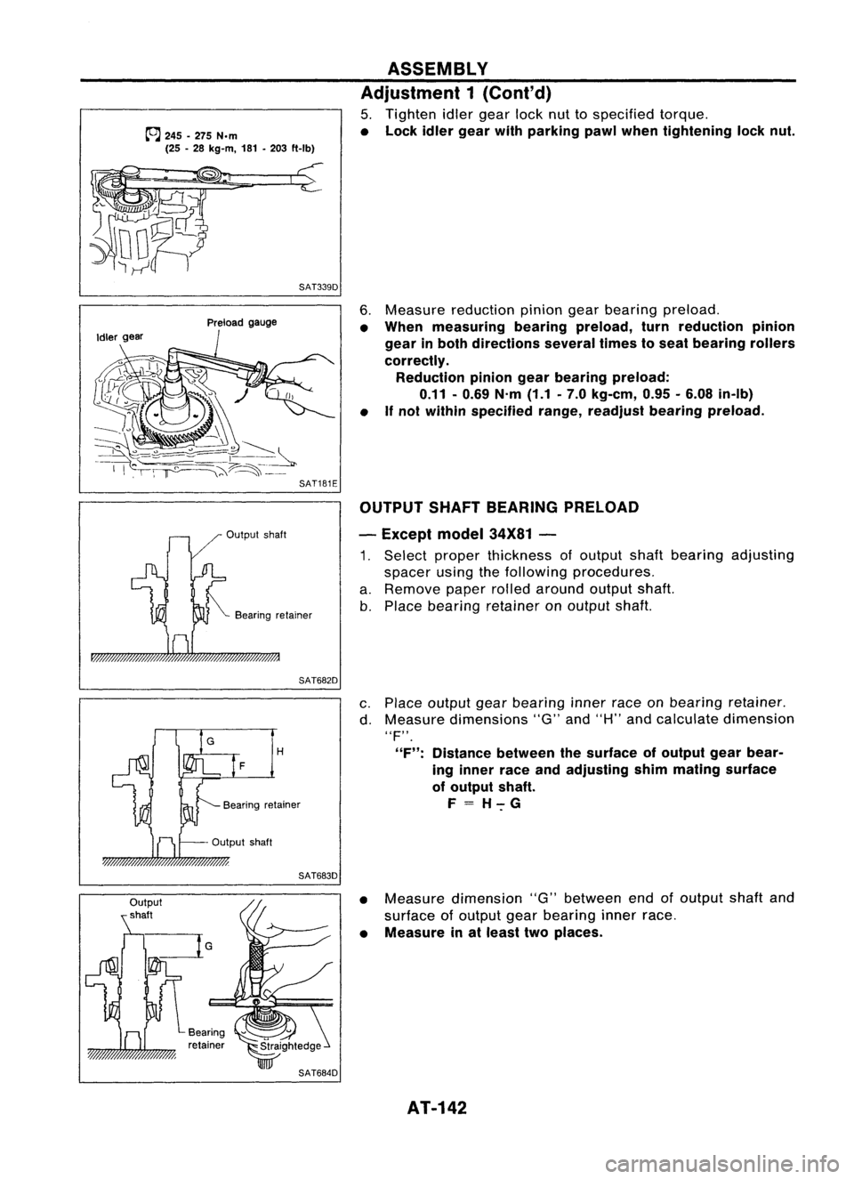
~245 -275 N.m
(25 -28 kg-m, 181-203 ft-Ib)
SAT339D ASSEMBLY
Adjustment 1(Cont'd)
5. Tighten idlergear locknuttospecified torque.
• Lock idlergear withparking pawlwhen tightening locknut.
Output shaft
Preload
gauge
Bearing retainer
6.
Measure reduction piniongearbearing preload.
• When measuring bearingpreload, turnreduction pinion
gear inboth directions severaltimestoseat bearing rollers
correctly. Reduction piniongearbearing preload:
0.11 -0.69 N.m(1.1.7.0 kg-em, 0.95•6.08 in-Ib)
• If
not within specified range,readjust bearingpreload.
OUTPUT SHAFTBEARING PRELOAD
- Except model34X81-
1. Select proper thickness ofoutput shaftbearing adjusting
spacer usingthefollowing procedures.
a. Remove paperrolledaround outputshaft.
b. Place bearing retainer onoutput shaft.
SAT682D
H
F
Output shaft
SAT683D
c.
Place output gearbearing innerraceonbearing retainer.
d. Measure dimensions "G"and"H" andcalculate dimension
"F".
"F": Distance betweenthesurface ofoutput gearbear-
ing inner raceandadjusting shimmating surface
of output shaft.
F=H-:-G
• Measure dimension "G"between endofoutput shaftand
surface ofoutput gearbearing innerrace.
• Measure inat least twoplaces.
AT-142
Page 144 of 1701
SAT689DASSEMBLY
Adjustment 1(Cont'd)
7. Tighten outputgearlocknuttospecified torque.
SAT702D
8.
Remove idlergear tomeasure outputshaftbearing preload.
9. Measure outputshaftbearing preload.
• When measuring bearingpreload, turnoutput shaftinboth
directions severaltimestoseat bearing rollerscorrectly.
Output shaftbearing preload:
0.25 -0.88 N'm
(2.5 -9.0 kg-em, 2.2-7.8 in-Ib)
10. Install idlergear andtighten locknuttospecified torque.
11. After properly adjusting "turning"torque,clinchidlergear
and output gearlocknuts asshown.
12. Install newgasket andside cover ontransmission case.
• Always replace sidecover bolts.
AT-144
Page 146 of 1701

SAT440DASSEMBLY
Adjustment 1(Cont'd)
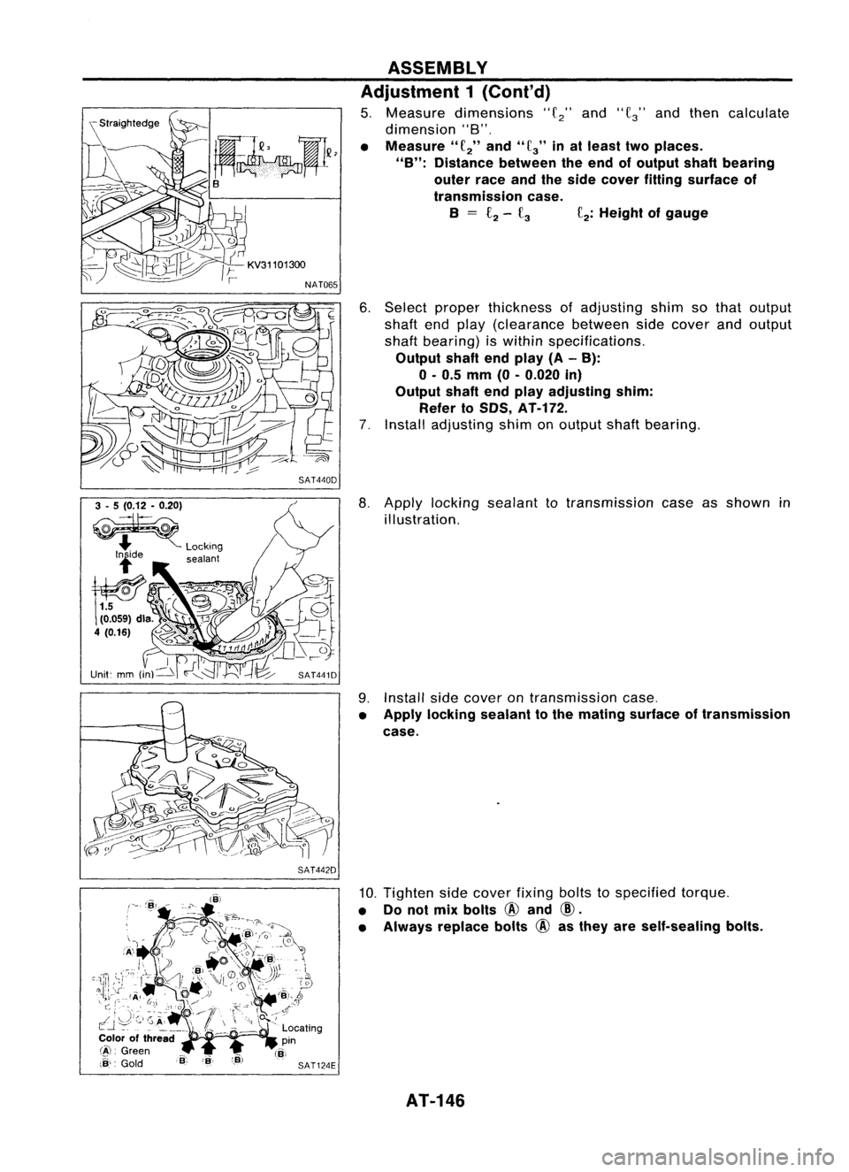
5. Measure dimensions
"f
2"
and
"f
3"
andthen calculate
dimension "8".
• Measure"
f
2"
and"
fa"
inat least twoplaces.
"B": Distance betweentheend ofoutput shaftbearing
outer raceandtheside cover fitting surface of
transmission case.
B
=
£2-
fa
f
2:
Height ofgauge
6. Select proper thickness ofadjusting shimsothat output
shaft endplay (clearance betweensidecover andoutput
shaft bearing) iswithin specifications.
Output shaftendplay (A-B):
o -
0.5
mm
(0-0.020
in)
Output shaftendplay adjusting shim:
Refer to50S,
AT-H2.
7. Install adjusting shimonoutput shaftbearing.
3 -5 (0.12 -0.20)
~
.... Locking
lide sealant
SAT441D
SAT442D
8.
Apply locking sealant totransmission caseasshown in
illustration.
9. Install sidecover ontransmission case.
• Apply locking sealant tothe mating surface oftransmission
case.
10. Tighten sidecover fixingboltstospecified torque.
• Donot mix bolts
@
and
CID.
• Always replace bolts
@
asthey areself-sealing bolts.
AT-146
Page 156 of 1701
ASSEMBLY
Assembly 3(Cont'd)
8. Tighten oilpump fixing boltstospecified torque.
9. Install O-ring toinput shaft.
• Apply ATFtoO-ring.
10. Adjust brakeband.
a. Tighten anchorendpintospecified torque.
Anchor endpin:
Ill:
3.9-5.9 N.m (0.4-0.6 kg-m, 35-52 in-Ib)
b. Back offanchor endpintwo and ahalf turns.
c. While holding anchorendpin,tighten locknut.
AT-156