Page 47 of 1701

MAJOROVERHAUL
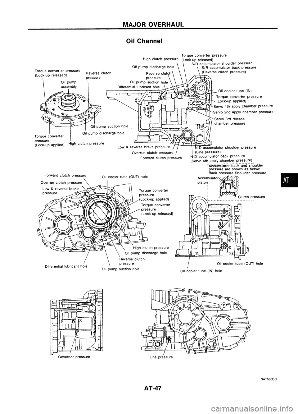
Oil Channel
High clutch pressure
Oilcooler tube(OUT) hole
•
Oil
cooler tube
(IN)
Torque converter pressure
(Lock-up applied)
" Servo
4th
apply chamber pressure
Servo 2ndapply chamber pressure
• Servo 3rdrelease
chamber pressure
Torque
converter pressure
(Lock-up released)
SIR accumulator shoulderpressure
SIR accumulator backpressure
(Reverse clutchpressure)
Oil cooler tube
(IN)
hole
Torque
converter
pressure (Lock-up applied)
Torque converter
pressure (Lock-up released)
reverse
brakepressure
Overrun clutchpressure
Forward clutchpressure
High
clutch pressure
Reverse clutch
pressure
Oil pump suction hole
Differential lubricanthole
High clutch pressure
Oil pump discharge hole
Reverse clutch
pressure
Oil pump suction hole
Reverse
clutch
pressure
Low
&
Oil
pump suction hole
Oil pump discharge hole
Forward clutchpressure
Overrun clutchpressure
Low
&
reverse brake
pressure
Torque
converter pressure
(Lock-up released)
Torque converter
pressure (Lock-up applied)
Governor pressure
Linepressure
SAT586DC
AT-47
Page 50 of 1701
DISASSEMBLY
J!in plug
1.
Drain ATFthrough drainplug.
SAT007D
2.Remove torqueconverter.
3. Check torque converter one-wayclutchusingcheck toolas
shown atleft.
a. Insert checktoolintothegroove ofbearing supportbuiltinto
one-way clutchouterrace.
b. While fixingbearing supportwithcheck tool,rotate one-way
clutch spline usingflat-bladed screwdriver.
c. Check innerracerotates clockwise only.Ifnot, replace
torque converter assembly.
/
SAT009D
One-way
clutch
~:e2
/ I
;,cr~~ar~ /
-
~
/
Bend awire anduse
it as acheck tool.
.----:-
Approx. 3.0(0.118)
[Bend a1.5 (0.059) die..
wire Inhall.]
Outer race
g
....
Unit: mm(in)
..
2
:
Approx.
15 (0.59)
4.Remove oilcharging pipeandoilcooler tube.
SAT586H AT-50
Page 75 of 1701
SAT245EB
Nut
Section Z- Z
Reamer bolt
•
Bolt
symbol
@
@ @@
CID
cD
Bolt length 'T'
13.558.0 40.0 66.033.078.0
~Qmm(in)
(0.531)
(2.283)(1.575)(2.598) (1.299)
(3.071)
Number ofbolts
4
3 611
22
Bolt symbol
@
@ @@
CID
CD
Bolt length" ("
13.558.0 40.0
66.0 33.078.0
~ (0.531)(2.283)
(1.575)(2.598) (1.299)(3.071)
>-,-1
Qmm (in)
Number ofbolts
53 611
22
With
torque converter clutchsolenoid valve
@
@
REPAIR
FORCOMPONENT PARTS
Control ValveAssembly (Cont'd)
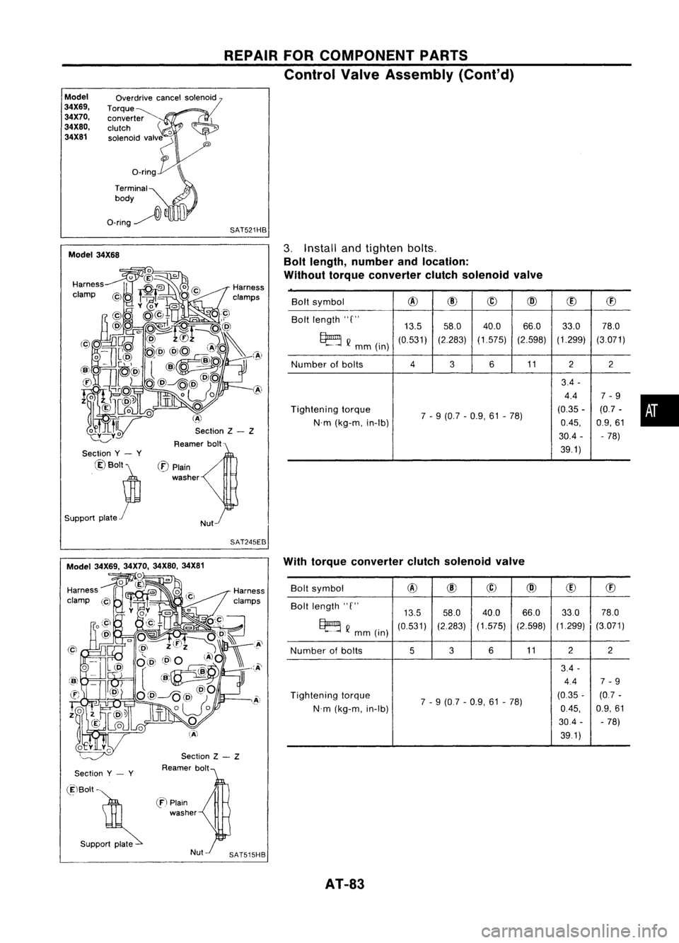
2. Disassemble upper,interandlower bodies usingthefollow-
ing procedures.
Bolt length, number andlocation:
Without torqueconverter clutchsolenoid valve
CD
Plain
washer
Section
y- y
Model
34X68
Section Y- Y
@Bolt~
Support plate
f
(E)BOIt~
Support plate~
(f)
Plain
washer
Nut SAT515HB
Model 34X68
a.
Remove bolts@,@and
CB
shown inthe illustration.
b. Remove oilstrainer fromcontrol valveassembly.
AT-75
Page 76 of 1701
Model34X69. 34X70.34X80,34X81 REPAIR
FORCOMPONENT PARTS
Control ValveAssembly (Cont'd)
Model 34X68
c.
Remove aDcancel solenoid fromcontrol valveassembly.
(Model 34X68)
Model 34X69. 34X70,34X80.34X81
~)
Model 34X68
Ori~
Torque
converter
clutch
solenoid
valve
SAT519HB
SAT240EB
d.
Remove aDcancel solenoid andtorque converter clutch
solenoid valvefromcontrol valveassembly. (Model34X69,
34X70, 34X80, 34X81)
e. Remove a-ringsfromaDcancel solenoid, andharness ter-
minal body. (Model 34X68)
ModeJ
34X69.
34X70.
34X80.
34X81
Overdrive
cancelsolenoid
Torque
converter
clutch
'0
solenoid valv~
"
o_rin~
Terminal
0
body
O-ring~
l\
SAT521HB
f.
Remove a-ringsfromaDcancel solenoid, torqueconverter
clutch solenoid valveandharness terminal body.(Model
34X69, 34X70, 34X80,34X81)
AT-76
Page 79 of 1701
REPAIRFORCOMPONENT PARTS
Control ValveAssembly (Cont'd)
INSPECTION
Lower andupper bodies
• Check tosee that retainer platesareinproper position in
lower body.
SAT113D
•Check tosee that retainer platesareinproper position in
upper body.
• Becareful nottolose these parts.
Oil strainer
• Check wirenetting ofoil strainer fordamage.
•
Oil strainer
Model 34X68 SAT115D
Overdrive cancelsolenoid
SAT608DB 00
cancel solenoid andtorque converter clutchsolenoid
valve
• Measure resistance -Refer to"Electrical Components
Inspection", AT-3D.
Model 34X69, 34X70,34X80, 34X81
Overdrive cancelsolenoid
Torque converter
clutch solenoid valve
SAT522HBAT-79
Page 82 of 1701
Lowerseparating
gasket REPAIR
FORCOMPONENT PARTS
Control ValveAssembly (Cont'd)
g. Install newlower separating gasket,newlower intersepa-
rating gasket andlower separating plateinorder shown in
illustration.
Lower separating
plate
SAT244E
Separating
plate &gaskets
Lowerbody
> (~)
Boit
SAT124DA
h.
Install support platefixing bolts
CID
from bottom oflower
body andinstall separating gasketsandseparating plateas
a set onlower bodyusing bolts
CID
asguides.
SAT125DA
i.
Temporarily installsupport platesonlower body.
Model 34X68 Lower
body
Inter and
upper bodies
SAT126D
Overdrive cancelsolenoid 7
.'
j.
Install lowerbodyoninter body using reamer bolts
(f)
as
guides andtighten reamer bolts
(f)
slightly.
2. Install a-rings toaD cancel solenoid, torqueconverter
clutch solenoid valveandharness connector.
• Apply ATF
toO-rings.
AT-82
Page 83 of 1701

REPAIRFORCOMPONENT PARTS
Control ValveAssembly (Cont'd)
Model
34X69, 34X70,
34X80, 34X81 Overdrive
cancelsolenoid
Torque~ converter
clutch
'0
solenoid valv~
'"
o_rin~
Terminal
0
body
O-ring~
l\
SAT521HB
Section Z- Z
Reamer bolt
Model
34X68
•
Bolt
symbol
@
@
@
@
(!)
ffi
Bolt length "C"
13.558.0 40.0 66.0
33.078.0
~ Q
mm(in)
(0.531)
(2.283)(1.575) (2.598)(1.299)
(3.071)
Number ofbolts
4
3611
22
3.4 -
4.4 7-9
Tightening torque
7-9 (0.7 -0.9, 61-78) (0.35
-(0.7 -
N'm (kg-m, in-Ib)
0.45,
0.9,61
30.4 - -78)
39.1)
3.
Install andtighten bolts.
Bolt length, number andlocation:
Without torqueconverter clutchsolenoid valve
/
Nut
(:E)
Plain
washer
Section
y- y
@Bolt~
Support plate
r
SAT245EB
Section
y- y
Section
Z- Z
Reamer bolt With
torque converter clutchsolenoid valve
Bolt symbol
@
@
@
@
(!)
ffi
Bolt length "C"
13.558.0
40.0 66.033.0
78.0
~ Q
mm (in)
(0.531)
(2.283)
(1.575) (2.598)(1.299)
(3.071)
Number ofbolts
536
11 2
2
3.4 -
4.4 7-9
Tightening torque
7-9 (0.7 -0.9, 61-78) (0.35
-(0.7 -
N'm (kg-m, in-Ib)
0.45,
0.9,61
30.4 --
78)
39.1)
(ElBolt -
. S"PP~
en
Plain
washer
AT-83
Page 84 of 1701
REPAIRFORCOMPONENT PARTS
Control ValveAssembly (Cont'd)
a. Install andtighten bolts
@
slightly.
SAT609D
Model 34X68
b.
Install ODcancel solenoid tolower body.(Model 34X68)
c. Install ODcancel solenoid andtorque converter clutchsole-
noid valve tolower body.(Except model34X68)
d. Install andtighten bolts
@
and
@
slightly.
e. Remove bothreamer bolts
(f)
previously installedas
guides. Installonereamer bolt
(f)
(marked inillustration)
from lower bodyside.
f.
Tighten bolts
@,
@,
@
and
(f)
tospecified torque.
~: 7-
9 N'm (0.7-0.9 kg-m, 61-78 in-Ib)
SAT525HA
00 cancel
solenoid
SAT526HB
g.Install oilstrainer andtheother bolt
CB
(marked in
illustration), thentighten bolts
@,
@
and
CB
tospecified
torque.
~: 7-
9 N'm (0.7-0.9 kg-m, 61-78 in-Ib)
Oil
strainer
SAT516HA
AT-84