Page 301 of 1701
((I
~i
i
U
Commercial service tool
SBR025D
SBR646
SBR868C! SBR889 REAR
DISCBRAKE
Removal
WARNING:
Clean brakepadswithavacuum dustcollector tominimize the
hazard ofairborne particles orother materials.
1. Remove
parkingbrakecablelockplate.
2. Remove torquemember fixingboltsandconnecting bolt.
It is not necessary toremove connecting boltexcept fordisas-
sembly orreplacement ofcaliper assembly. Inthis case, sus-
pend caliper assembly withwire soas not tostretch brake
hose.
Disassembly
1. Remove pistonbyturning itcounterclockwise withsuitable
long nose pliers orcommercial
service
tool.
2. Remove snapringfrom piston withsuitable pliersand
remove adjusting nut.
•
3. Disassemble cylinderbody.
a. Pry offsnap ringwith suitable pliers,thenremove spring
cover, spring andseat.
b. Remove snapring,then remove keyplate, pushrod,rod
and strut.
BR-31
Page 302 of 1701

l
--,II
~//
SBR656
SBR026D REAR
DISCBRAKE
Disassembly (Cont'd)
c. Remove pistonseal.
Be careful nottodamage cylinderbody.
4. Remove returnspring, toggleleverandcable guide.
Inspection -Caliper
CAUTION: Use brake fluidtoclean cylinder. Neverusemineral
oil.
CYLINDER BODY
• Check insidesurface ofcylinder forscore, rust,wear, dam-
age orpresence offoreign objects. Ifany ofthe above con-
ditions areobserved, replacecylinder body.
• Minor damage fromrustorforeign objects maybeelimi-
nated bypolishing surfacewithafine emery paper.
Replace cylinder bodyifnecessary.
TORQUE MEMBER
Check forwear, cracks orother damage. Replaceifnecessary.
PISTON
CAUTION:
Piston sliding surface ;splated. Donot polish withemery paper
even ifrust orforeign objects isstuck tosliding surface.
Check pistonforscore, rust,wear, damage orpresence offor-
eign objects. Replace ifany ofthe above conditions are
observed.
SLIDE PIN,PINBOLT, ANDPINBOOT
Check forwear, cracks orother damage.
Replace ifany ofthe above conditions areobserved.
BR-32
Page 360 of 1701

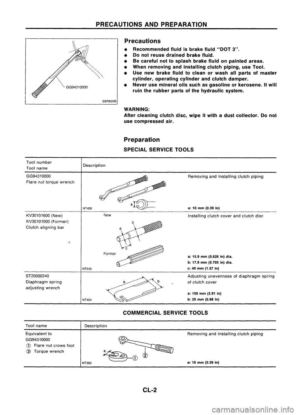
PRECAUTIONSANDPREPARATION
Precautions
• Recommended fluidisbrake fluid"DOT 3".
• Donot reuse drained brakefluid.
• Becareful nottosplash brakefluidonpainted areas.
• When removing andinstalling clutchpiping, useTool.
• Use new brake fluidtoclean orwash allparts ofmaster
cylinder, operating cylinderandclutch damper.
• Never usemineral oilssuch asgasoline orkerosene. Itwill
ruin therubber partsofthe hydraulic system.
Tool number
Tool name
SBR820B
WARNING:
After cleaning clutchdisc,wipe itwith adust collector. Donot
use compressed air.
Preparation
SPECIAL SERVICE TOOLS
Description
New
GG94310000
Flare nuttorque wrench
KV30101600 (New)
KV30101000 (Former)
Clutch aligning bar
ST20050240 Diaphragm spring
adjusting wrench
NT406
NT645
NT404
Removing
andinstalling clutchpiping
a:
10
mm
(0.39
in)
Installing clutchcoverandclutch disc:
a:
15.9
mm
(0.626 In)dia.
b: 17.9 mm(0.705 in)dia.
c: 40 mm (1.57 in)
Adjusting unevenness ofdiaphragm spring
of clutch cover
a: 150 mm (5.91 in)
b: 25
mm
(0.98
in)
Tool name
Description
COMMERCIAL
SERVICETOOLS
Equivalent to
GG9431 0000
CD
Flare nutcrows foot
@
Torque wrench
NT360
Removing
andinstalling clutchpiping
a: 10 mm (0.39 in)
CL-2
Page 538 of 1701
~Wiperamplifier
~~
t
Test lamp
SEL842TWIPER
ANDWASHER
Front Wiper Amplifier Check
1. Connect asshown inthe figure atleft.
2. Iftest lamp comes onwhen connected toterminal
CD
or
@
and battery ground, wiperamplifier isnormal.
GEL028
SEL024J Front
Wiper Installation andAdjustment
1. Prior towiper arminstallation, turnonwiper switch tooper-
ate wiper motor andthen turnit"OFF" (AutoStop).
2. Liftthe blade upand then setitdown ontoglass surface. Set
the blade center toclearance "C"
&
"D" immediately before
tightening nut.
3. Eject washer fluid.Turnonwiper switch tooperate wiper
motor andthen turnit"OFF".
4. Ensure thatwiper blades stopwithin clearance "C"
&
"D".
Clearance
"C":
23-38 mm (0.91 •1.50 in)
Clearance
"0":
27-42 mm (1.06 -1.65 in)
• Tighten windshield wiperarmnuts tospecified torque.
~: 21-26 N'm (2.1-2.7 kg-m, 15-20 ft.lb)
• Before reinstalling wiperarm,clean upthe pivot areaas
illustrated. Thiswillreduce possibility ofwiper armloose-
ness.
EL-166
Page 547 of 1701

~~:;"f1.'
~
C!E:TIJ
!II8EITJ
SEL846TWIPER
ANDWASHER
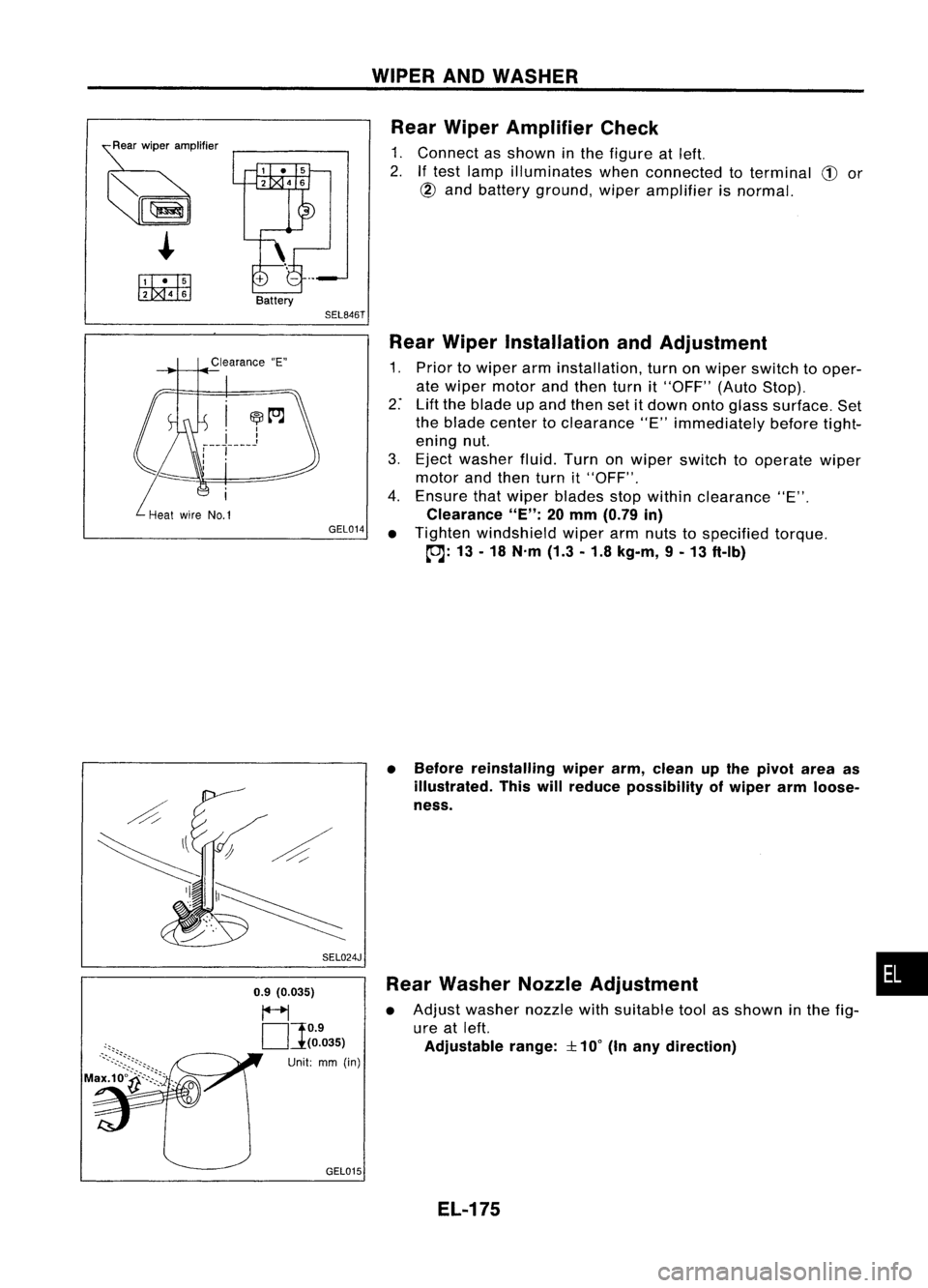
Rear Wiper Amplifier Check
1. Connect asshown inthe figure atleft.
2.
If
test lamp illuminates whenconnected toterminal
CD
or
@
and battery ground, wiperamplifier isnormal.
Clearance "E"
GEL014
SEL024J
0.9 (0.035)
~
OJ
O.9
(0.035)
Unit: mm(in)
GEL015 Rear
Wiper Installation andAdjustment
1. Prior towiper arminstallation, turnonwiper switch tooper-
ate wiper motor andthen turnit"OFF" (AutoStop).
2: Liftthe blade upand then setitdown ontoglass surface. Set
the blade center toclearance "E"immediately beforetight-
ening nut.
3. Eject washer fluid.Turnonwiper switch tooperate wiper
motor andthen turnit"OFF".
4. Ensure thatwiper blades stopwithin clearance "E".
Clearance
"E":
20mm (0.79 in)
• Tighten windshield wiperarmnuts tospecified torque.
~: 13-18 N.m (1.3-1.8 kg-m, 9-13 ft-Ib)
• Before reinstalling wiperarm,clean upthe pivot areaas
illustrated. Thiswillreduce possibility ofwiper armloose-
ness.
Rear Washer NozzleAdjustment
• Adjust washer nozzlewithsuitable toolasshown inthe fig-
ure atleft.
Adjustable range:
::l::
10°
(Inany direction)
EL-175
•
Page 551 of 1701

.WIPER ANDWASHER
SEL244P Headlamp
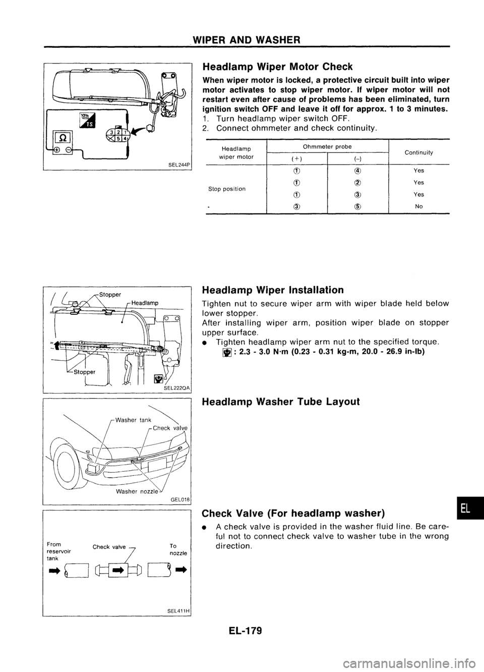
WiperMotorCheck
When wiper motor islocked, aprotective circuitbuiltintowiper
motor activates tostop wiper motor. Ifwiper motor willnot
restart evenaftercause ofproblems hasbeen eliminated, turn
ignition switchOFFandleave itoff for approx. 1to 3minutes.
1. Turn headlamp wiperswitch OFF.
2. Connect ohmmeter andcheck continuity.
Headlamp Ohmmeter
probe
Continuity
wiper motor
(+)
H
(!) @
Yes
(!)
@
Yes
Stop position
(!)
CID
Yes
.
CID
@)
No
From
.. 0
c~'..
~'fo
reservoir
tank GEL018
To
nozzle
0"
SEL411H Headlamp
WiperInstallation
Tighten nuttosecure wiperarmwith wiper bladeheldbelow
lower stopper.
After installing wiperarm,position wiperbladeonstopper
upper surface.
• Tighten headlamp wiperarmnuttothe specified torque.
~ :2.3 -3.0 N'm (0.23 -0.31 kg-m, 20.0-26.9 in-Ib)
Headlamp WasherTubeLayout
Check Valve(Forheadlamp washer)
• Acheck valveisprovided inthe washer fluidline.Becare-
ful not toconnect checkvalvetowasher tubeinthe wrong
direction.
EL-179
•
Page 684 of 1701
PRECAUTIONSANDPREPARATION
Precautions
• When installing rubberparts,finaltightening mustbecar-
ried outunder unladen condition* withtires onground.
*: Fuel, radiator coolantandengine oilfull. Spare tire,
jack,
hand tools andmats indesignated positions.
• After installing removedsuspension parts,check wheel
alignment andadjust ifnecessary.
• Use flare nutwrench whenremoving orinstalling brake
tubes.
• Always torquebrakelineswhen installing.
Tool number
Tool name
SBR820B
Special Service Tools
Description
HT72520000
Ball joint remover Removing
tie-rodouterendandlower ball
joint
NT146
HT71780000
Spring compressor
ST35652000
Strut attachment
NT144
Removing
andinstalling coilspring
Fixing strutassembly
NT145
GG94310000
Flare nuttorque wrench
KV38106700
KV381 06800
Differential sideoilseal
protector
NT406
NT147
FA-2
Removing
andinstalling brakepiping
a:
10mm (0.39 in)
Installing driveshaft
LH: KV38106700
RH: KV38106800
Page 685 of 1701
Toolname
Front wheel hubdrift
PRECAUTIONS
ANDPREPARATION
Commercial ServiceTools
Description Removingwheelhub
Front wheel bearing outer
race drift
Grease sealdrift
Attachment
Wheel alignment
Equivalent toGG94310000
G)
Flare nutcrows foot
GV
Torque wrench
NT065
NT115
NT115
NT148
NT360
FA-3
a:
42 mm (1.65 in)dia.
b: 33mm (1.30 in)dia.
Removing andinstalling wheelbearing
outer race
a: 76mm (2.99 in)dia.
b: 72mm (2.83 in)dia.
Installing outergrease seal
a: 81mm (3.19 in)dia.
b: 76mm (2.99 in)dia.
Measuring wheelalignment
a: Screw M22x1.5
b: 35(1.38) dia.
c: 65 (2.56) dia.
d: 56(2.20)
e: 12(0.47)
Unit mm(in)
Removing andinstalling brakepiping
a: 10mm (0.39 in)
•