Page 940 of 1701

TROUBLEDIAGNOSIS FORNON-DETECTABLE ITEMS~
Torque Converter ClutchSolenoid Valve(Cont'd)
SYSTEM DESCRIPTION
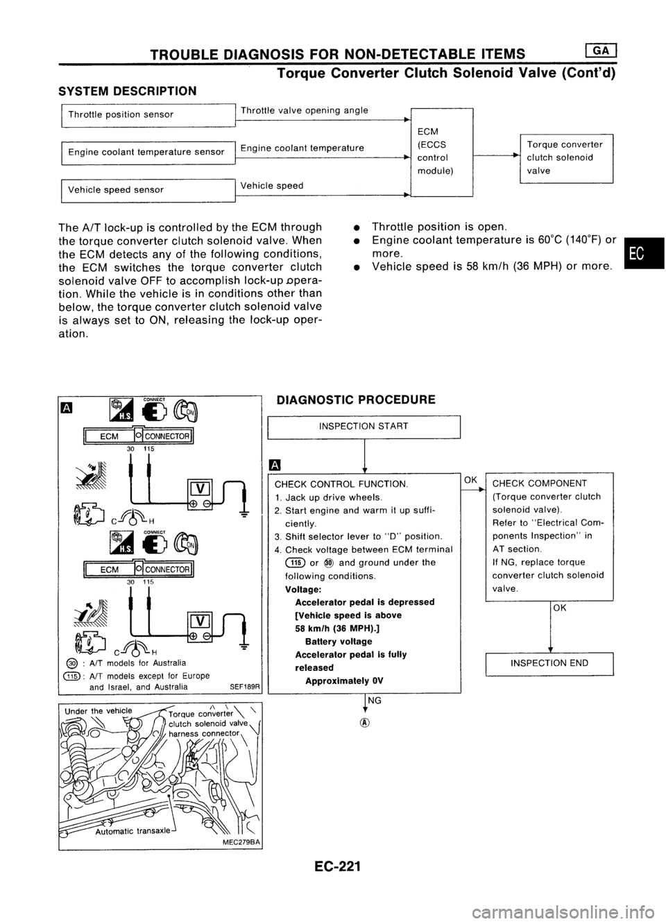
Throttle position sensor Throttle
valveopening angle
Engine coolant temperature sensorEnginecoolant temperature ECM
(ECCS
control
module) Torque
converter
clutch solenoid
valve
Vehicle speedsensor Vehicle
speed
The
AfT
lock-up iscontrolled bythe ECM through
the torque converter clutchsolenoid valve.When
the ECM detects anyofthe following conditions,
the ECM switches thetorque converter clutch
solenoid valveOFFtoaccomplish lock-upDpera-
tion. While thevehicle isin conditions otherthan
below, thetorque converter clutchsolenoid valve
is always settoON, releasing thelock-up oper-
ation.
•
•
•
Throttle
position isopen .
Engine coolant temperature is60°C (140°F) or•
more.
Vehicle speedis58 kmfh (36MPH) ormore .
m ~
i3~
II
ECM
HCONNECTORII
30 115
ID
cf6~H
~i3~
II
ECM E
CONNECTOR
II
30 115
iIJ
ID
cf6~H
@> :
AIT
models forAustralia
@:
AlTmodels exceptforEurope
and Israel, andAustralia
SEF189RDIAGNOSTIC
PROCEDURE
INSPECTION START
CHECK CONTROL FUNCTION.
1. Jack updrive wheels.
2. Start engine andwarm itup suffi-
ciently.
3. Shift selector leverto"D" position.
4. Check voltage between ECMterminal
GID
or
@
and ground underthe
following conditions.
Voltage: Accelerator pedalisdepressed
[Vehicle speedisabove
58 km/h (36MPH).]
Battery voltage
Accelerator pedalisfully
released ApprOXimately OV
OK
CHECK COMPONENT
(Torque converter clutch
solenoid valve).
Refer to"Electrical Com-
ponents Inspection" in
AT section.
If NG, replace torque
converter clutchsolenoid
valve.
OK
INSPECTION END
MEC279BA NG
EC-221
Page 941 of 1701
![NISSAN ALMERA N15 1995 Service Manual TROUBLEDIAGNOSIS FORNON-DETECTABLE ITEMS
@]
Torque Converter ClutchSolenoid Valve(Cont'd)
@
@ :
AIT
models forAustralia
@:
NTmodels exceptforEurope
and Israel, andAustralia
I!J
1
CHECK POW NISSAN ALMERA N15 1995 Service Manual TROUBLEDIAGNOSIS FORNON-DETECTABLE ITEMS
@]
Torque Converter ClutchSolenoid Valve(Cont'd)
@
@ :
AIT
models forAustralia
@:
NTmodels exceptforEurope
and Israel, andAustralia
I!J
1
CHECK POW](/manual-img/5/57349/w960_57349-940.png)
TROUBLEDIAGNOSIS FORNON-DETECTABLE ITEMS
@]
Torque Converter ClutchSolenoid Valve(Cont'd)
@
@ :
AIT
models forAustralia
@:
NTmodels exceptforEurope
and Israel, andAustralia
I!J
1
CHECK POWER SUPPLY. NG
Check thefol/owing.
1. Stop engine.
--.--..
•Harness connectors
2. Disconnect torqueconverter clutch
@),
solenoid valveharness connector. •10A fuse
3. Turn ignition switch"ON".
•Harness foropen or
4. Check voltage between terminal
@
shortbetween torque
and ground. converterclutchsole-
Voltage: Batteryvoltage
noidvalve andfuse
" NG, repair harness or
OK connectors.
[;J
CHECK OUTPUT SIGNALCIRCUIT. NG
Check thefollowing.
1. Turn ignition switch"OFF".
--.--..
•Harness connectors
2. Disconnect ECMharness connector.
aD,@
3. Check harness continuity between •Harness connectors
ECM terminal
(ill)
or
@
and termi-
@,@!)
nal (D. •Harness connectors
Continuity shouldexist.
@),@D
" OK, check harness forshort. •
Harness foropen or
short between ECM
OK andtorque converter
clutch solenoid valve
If
NG, repair harness or
connectors.
CHECK COMPONENT NG
Replace torqueconverter
(Torque converter clutchsolenoid
~
clutchsolenoid valve.
valve).
Refer to"Electrical Components
Inspection" inAT section.
OK
Disconnect andreconnect harnesscon-
nectors inthe circuit. Thenretest.
Trouble isnot fixed.
Check ECMpinterminals fordamage
or the connection ofECM harness con-
nector. Reconnect ECMharness con-
nector andretest.
.
INSPECTION END
SEF190R
SEF513Q
rilio
ECM
HCONNECTORII
115 30
~i5
~
II
EC-222
Page 960 of 1701

~U5e
box
~~~
~11~1-
Datalinkconnector ~"
for CONSULT
t=====/
• FUEL PRESRELEASE. D
FUEL PUMP WillSTOP BY
TOUCHING STARTDURING
IDLE.
CRANK AFEW TIMES AFTER
ENGINE STALL
---S-T~-RT--
BASIC
SERVICE PROCEDURE
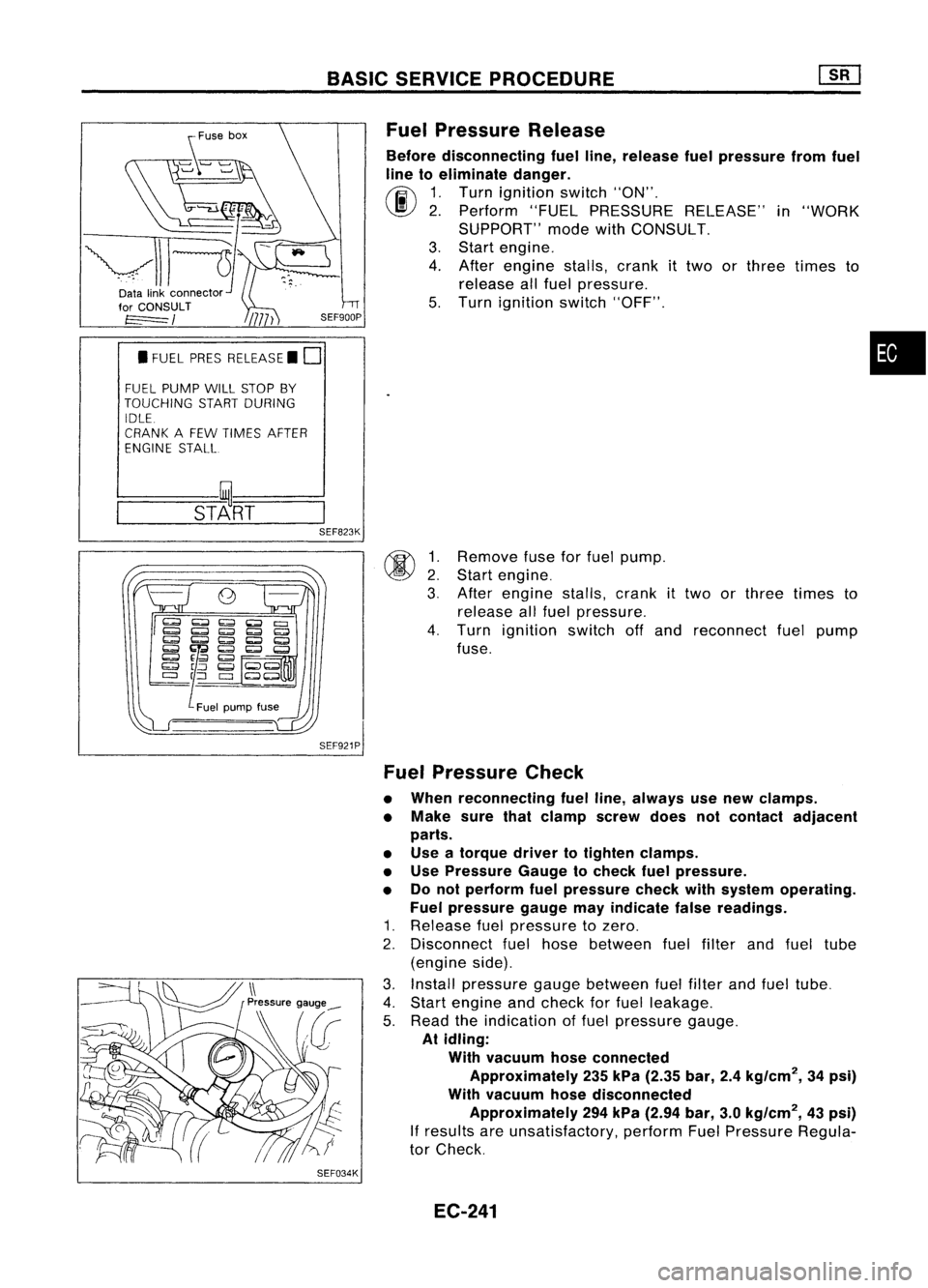
Fuel Pressure Release
Before disconnecting fuelline, release fuelpressure fromfuel
line toeliminate danger.
~ 1.Turn ignition switch"ON".
\J!I}
2.Perform "FUELPRESSURE RELEASE"in"WORK
SUPPORT" modewithCONSULT.
3. Start engine.
4. After engine stalls,crankittwo orthree times to
release allfuel pressure.
5. Turn ignition switch"OFF".
•
@ ~:
3.
SEF823K
SEF921P
SEF034K
Remove
fuseforfuel pump.
Start engine.
After engine stalls,crank
it
two orthree times to
release allfuel pressure.
4. Turn ignition switchoffand reconnect fuelpump
fuse.
Fuel Pressure Check
• When reconnecting fuelline, always usenew clamps.
• Make surethatclamp screwdoesnotcontact adjacent
parts.
• Use atorque drivertotighten clamps.
• Use Pressure Gaugetocheck fuelpressure.
• Donot perform fuelpressure checkwithsystem operating.
Fuel pressure gaugemayindicate falsereadings.
1. Release fuelpressure tozero.
2. Disconnect fuelhose between fuelfilter andfuel tube
(engine side).
3. Install pressure gaugebetween fuelfilter andfuel tube.
4. Start engine andcheck forfuel leakage.
5. Read theindication offuel pressure gauge.
At idling:
With vacuum hoseconnected
Approximately 235kPa (2.35 bar,2.4kg/cm
2,
34psi)
With vacuum hosedisconnected
Approximately 294kPa (2.94 bar,3.0kg/cm
2,
43psi)
If
results areunsatisfactory, performFuelPressure Regula-
tor Check.
EC-241
Page 1004 of 1701
![NISSAN ALMERA N15 1995 Service Manual TROUBLEDIAGNOSIS -General Description
[]K]
ECM Terminals andReference Value(Cont'd)
'Data arereference values.
TERMINAL WIRE
ITEM CONDITION
'DATA
NO. COLOR
Ilgnitionswitch"ON"I
NISSAN ALMERA N15 1995 Service Manual TROUBLEDIAGNOSIS -General Description
[]K]
ECM Terminals andReference Value(Cont'd)
'Data arereference values.
TERMINAL WIRE
ITEM CONDITION
'DATA
NO. COLOR
Ilgnitionswitch"ON"I](/manual-img/5/57349/w960_57349-1003.png)
TROUBLEDIAGNOSIS -General Description
[]K]
ECM Terminals andReference Value(Cont'd)
'Data arereference values.
TERMINAL WIRE
ITEM CONDITION
'DATA
NO. COLOR
Ilgnitionswitch"ON"I
L
For 5seconds afterturning ignition switch
"ON" Approximately
OV
104 B/P Fuelpump relay !Engine
isrunning.1
Ilgnition switch"ON"I
BATTERY VOLTAGE
L
5seconds afterturning ignitionswitch
(11-14V)
"ON" andthereafter
IEngine isrunning.1
0.6-0.8V
EGR valve
&
EVAP
.L
Engine speedis4,000 rpm.
105 P canisterpurgecontrol
solenoid valve IEngine
isrunning.1
BATTERYVOLTAGE
L
Idle speed (11
-14V)
107 IEngine
isrunning.j
B/Y ECCSground
L
Engine
ground
108 Idlespeed
!Engine isrunning.1
Approximately0.2V
L
Engine speedisbelow 3,200rpm.
Heated oxygen sensor
111 OR
heater IEngineisrunning.1
BATTERY VOLTAGE
L
Engine speedisabove 3,200rpm. (11
-14V)
IEngine isrunning.\
11-14V
L
Idle speed
113 SB IACV-AAC
valve lEngine
isrunning.1
~ Sle«;ng wheel;,be;ng I"med
2-11V
Air conditioner isoperating.
Rear window defogger switchis"ON".
Lighting switchis"ON".
!Engine isrunning.1
ApproximatelyOV
Torque converter
L
Idle speed
115 P/B clutch
solenoid valve
IEngineisrunning.1 (Warm-up condition)
(A/T
models)
L
Vehicle speedis60 km/h (37MPH) or BA
TTERY VOLTAGE
(11 -14V)
more in"D" position
116 BIY ECCS
ground IEngine
isrunning.1
Engineground
L
Idle speed
EC-285
•
Page 1086 of 1701
TROUBLEDIAGNOSIS FORNON-DETECTABLE ITEMS~
Torque Converter ClutchSolenoid Valve
EC-LKUP-01
I
Q.61
Y
I
Y
1[~]Im
=r=~
Y
I
Y
r=b
TORQUE
~3 CONVERTER
CLUTCH
SOLENOID
11111 VALVE
=r=@ID
PIS
I
PIS
r=bm
1~1@g)
PIS
L
PIS~ PIS-PIS iJJ-
PIS
l
~(][) @@
PIS
IF1I5n
LKUP -:
Detectable line
for DTC
IGNITION
SWITCH
ON orSTART
10A
[]]
FUSE
SLOCK
(J/S)
Refer
toEL-POWER.
-:
Non-detectable
line forDTC
ECM (ECCS
CONTROL
MODULE)
em
•
~~,m
~ SGY
Refer
tolast page
(Foldout page).
EC-367
(IT)
L
HEC023
Page 1087 of 1701

TROUBLEDIAGNOSIS FORNON-DETECTABLE ITEMS~
Torque Converter ClutchSolenoid Valve(Cont'd)
SYSTEM DESCRIPTION
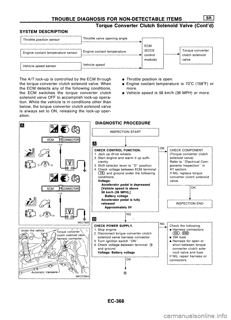
Throttle position sensor Throttle
valveopening angle
Engine coolant temperature sensorEnginecoolant temperature ECM
(ECCS
control
module) Torque
converter
clutch solenoid
valve
Vehicle speedsensor Vehicle
speed
The
AfT
lock-up iscontrolled bythe ECM through
the torque converter clutchsolenoid valve.When
the ECM detects anyofthe following conditions,
the ECM switches thetorque converter clutch
solenoid valveOFFtoaccomplish lock-upopera-
tion. While thevehicle isinconditions otherthan
below, thetorque converter clutchsolenoid valve
is always settoON, relea'sing thelock-up oper-
ation. •
Throttle position isopen .
• Engine coolant temperature is70°C (158°F) or
more .
• Vehicle speedis58 kmfh (36MPH) ormore.
~i3~
II
ECM
E[CONNECTORII
DIAGNOSTIC
PROCEDURE
INSPECTION START
115
OK
INSPECTION END
CHECK
COMPONENT
(Torque converter clutch
solenoid valve).
Refer to"Electrical Com-
ponents Inspection" in
AT section.
If
NG, replace torque
converter clutchsolenoid
valve.
Check thefollowing.
• Harness connectors
@,
• 10A fuse
• Harness foropen or
short between torque
converter clutchsole-
noid valve andfuse
If NG, repair harness or
connectors.
NG
OK
OK
@
CHECK
CONTROL FUNCTION.
1. Jack updrive wheels.
2. Start engine andwarm itup suffi-
ciently.
3. Shift selector leverto"0" position.
4. Check voltage between ECMterminal
GID
andground underthefollowing
conditions.
Voltage: Accelerator pedalIsdepressed
[Vehicle speedisabove
58 km/h (36MPH).]
Battery voltage
Accelerator pedalisfully
released
Approximately OV
CHECK POWER SUPPLY.
1. Stop engine.
2. Disconnect torqueconverter clutch
solenoid valveharness connector.
3. Turn ignition switch"ON".
4. Check voltage between terminal
@
and ground.
Voltage: Batteryvoltage
-
MEC785B
MEC279BA
Ef
CONNECTOR
II
115
II
ECM
~~
ID
cf8~-H
EC-368
Page 1088 of 1701
![NISSAN ALMERA N15 1995 Service Manual TROUBLEDIAGNOSIS FuRNON-DETECTABLE ITEMS
[![]
Torque Converter ClutchSolenoid Valve(Cont'd)
@
~i5
~
~i5
II
ECM
Ef
CONNECTOR
II
115 SEF513Q
~ SEF514Q CHECK
OUTPUT SIGNALCIRCUIT.
1. Turn NISSAN ALMERA N15 1995 Service Manual TROUBLEDIAGNOSIS FuRNON-DETECTABLE ITEMS
[![]
Torque Converter ClutchSolenoid Valve(Cont'd)
@
~i5
~
~i5
II
ECM
Ef
CONNECTOR
II
115 SEF513Q
~ SEF514Q CHECK
OUTPUT SIGNALCIRCUIT.
1. Turn](/manual-img/5/57349/w960_57349-1087.png)
TROUBLEDIAGNOSIS FuRNON-DETECTABLE ITEMS
[![]
Torque Converter ClutchSolenoid Valve(Cont'd)
@
~i5
~
~i5
II
ECM
Ef
CONNECTOR
II
115 SEF513Q
~ SEF514Q CHECK
OUTPUT SIGNALCIRCUIT.
1. Turn ignition switch"OFF".
2. Disconnect ECMharness connector.
3. Check harness continuity between
ECM terminal
@
andterminal
G).
Continuity shouldexist.
If OK, check harness forshort.
OK
CHECK COMPONENT
(Torque converter clutchsolenoid
valve).
Refer to"Electrical Components
Inspection" in
AT
section.
OK
Disconnect andreconnect harnesscon-
nectors inthe circuit. Thenretest.
Trouble isnot fixed
Check ECMpinterminals fordamage
and check theconnection ofECM har-
ness connector. ReconnectECMhar-
ness connector andretest.
INSPECTION END
EC-369 NG
NG
Check
thefollowing.
• Harness connectors
@@,@
• Harness connectors
@D,@
• Harness connectors
@,CID
• Harness foropen or
short between ECM
and torque converter
clutch solenoid valve
If NG, repair harness or
connectors.
Replace torqueconverter
clutch solenoid valve.
•
Page 1182 of 1701

Innerside
SEM164F PRECAUTIONS
Parts Requiring AngularTightening
• Use anangle wrench forthe final tightening ofthe follow-
ing engine parts:
(1) Cylinder headbolts
(2) Main bearing capbolts (SRengine only)
(3) Connecting rodcap nuts (SRand CDengine)
• Donot use atorque valueforfinal tightening. •
• The torque values forthese partsareforapreliminary step.
• Ensure threadandseat surfaces areclean andcoated with
engine oil.
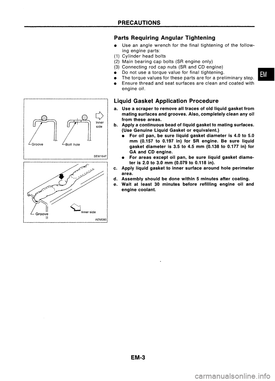
Liquid Gasket Application Procedure
a. Use ascraper toremove alltraces ofold liquid gasket from
mating surfaces andgrooves. Also,completely cleananyoil
from these areas.
b. Apply acontinuous beadofliquid gasket tomating surfaces.
(Use Genuine LiquidGasket orequivalent.)
• For oilpan, besure liquid gasket diameter is4.0 to5.0
mm (0.157 to0.197 in)for SR engine. Besure liquid
gasket diameter is3.5 to4.5 mm (0.138 to0.177 in)for
GA and CDengine.
• For areas except oilpan, besure liquid gasket diame-
ter is2.0 to3.0 mm (0.079 to0.118 in).
c. Apply liquidgasket toinner surface aroundholeperimeter
area.
d. Assembly shouldbedone within 5minutes aftercoating.
e. Wait atleast 30minutes beforerefilling engineoiland
engine coolant.
EM.3