Page 1204 of 1701

o
Cylinder
headboltwasher
0 __ 0
•
Cylinder headside
Tighten innumerical order.
~ 58.8 (6,43)
Ol
""
E
z
~ 29.4 (3,22)
E!"
2
Ol
c
'c
QJ
.E
Cl
i=
SEM877A
SEM124D
SEM614EA TIMING
CHAIN
[]K]
Installation (Cont'd)
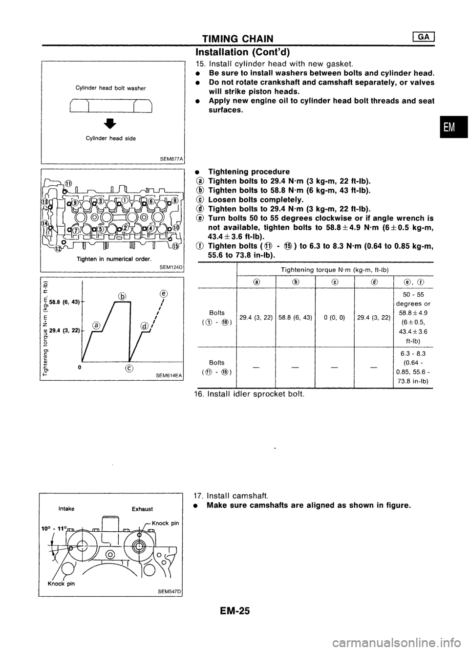
15. Install cylinder headwithnewgasket.
• Besure toinstall washers betweenboltsandcylinder head.
• Donot rotate crankshaft andcamshaft separately, orvalves
will strike piston heads.
• Apply newengine oiltocylinder headboltthreads andseat
surfaces.
• Tightening procedure
@
Tighten boltsto29.4 N'm (3kg-m, 22ft-Ib).
@
Tighten boltsto58.8 N'm(6kg-m, 43ft-Ib).
@
Loosen boltscompletely.
@
Tighten boltsto29.4 N'm (3kg-m, 22ft-Ib).
@
Turn bolts 50to55 degrees clockwise orifangle wrench is
not available, tightenboltsto58.8:1: 4.9N'm (6:1:0.5kg-m,
43.4:1: 3.6ft-Ib).
CD
Tighten bolts
(@-@)
to6.3 to8.3 N'm (0.64 to0.85 kg-m,
55.6 to73.8 in-Ib).
Tightening torqueN'm(kg-m, ft-Ib)
@
@
@
@
@,CD
50 -55
degrees or
Bolts 29.4(3,22) 58.8 (6,43) 0(0,0) 58.8:1:4.9
((1) -
@»)
29.4
(3,22)
(6:1:0.5,
43.4:1: 3.6
ft-Ib)
6.3 -8.3
Bolts (0.64
-
(@ -@)
-
- -
-
0.85,55.6 -
73.8 in-Ib)
16. Install idlersprocket bolt.
•
Intake Exhaust
17.
Install camshaft.
• Make surecamshafts arealigned asshown infigure.
SEM547D EM-25
Page 1214 of 1701

SEM154D
SEM549A CYLINDER
HEAD
Inspection (Cont'd)
CAMSHAFT RUNOUT
1. Measure camshaft runoutatthe center journal.
Runout (Totalindicator reading):
Standard: Less than0.02mm(0.0008 in)
Limit: 0.1 mm (0.004 in)
2. Ifitexceeds thelimit, replace camshaft.
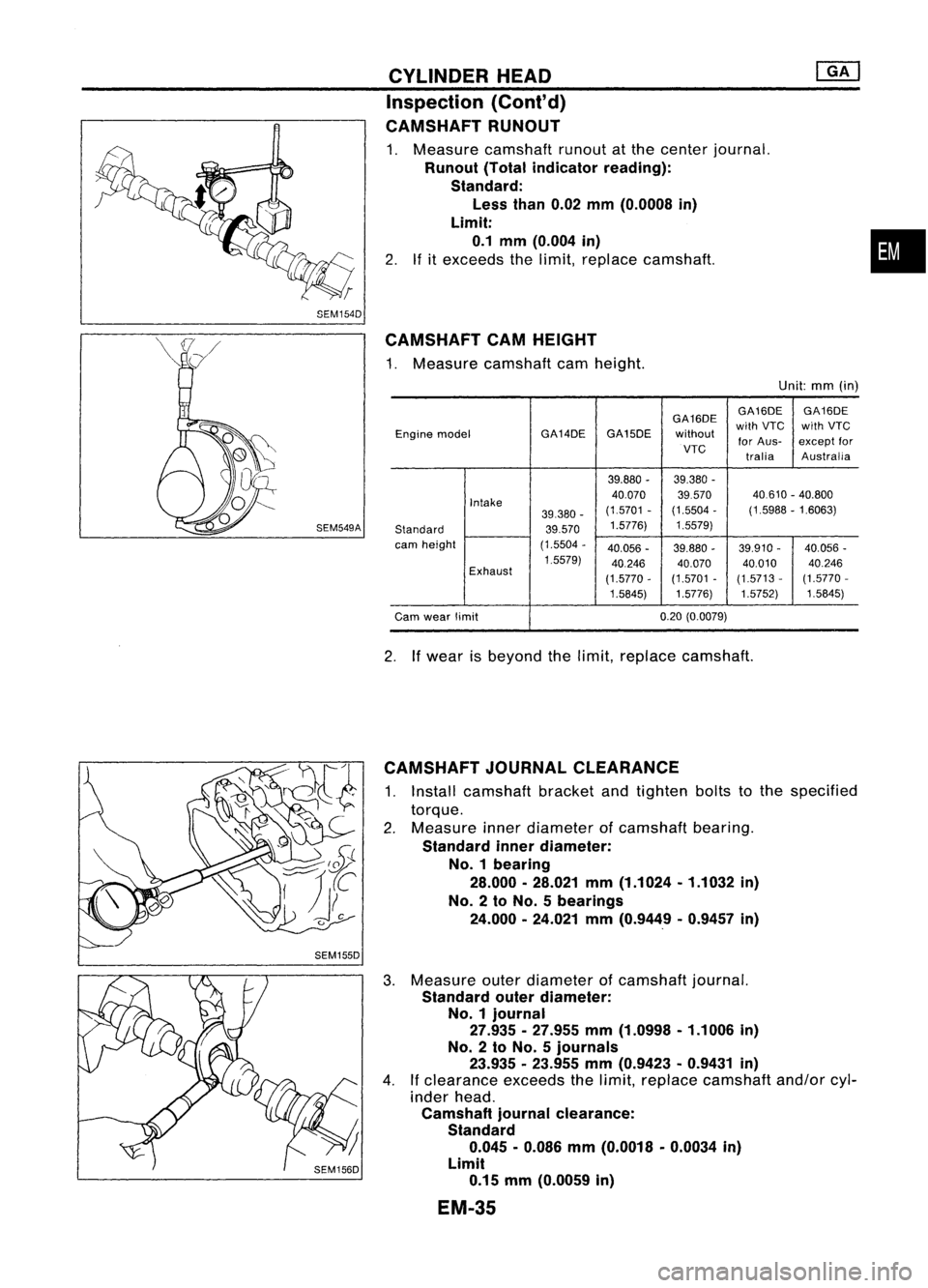
CAMSHAFT CAMHEIGHT
1. Measure camshaft camheight.
Unit:mm(in)
GA16DE GA16DE
GA16DE
Engine model GA14DEGA15DE
withoutwith
VTC withVTC
for Aus- except
for
VTC traliaAustralia
39.880 -39.380 -
Intake 40.070
39570 40.610
-40.800
39.380 -(1.5701
-(1.5504 -(1.5988 -1.6063)
Standard 39.5701.5776)
1.5579)
cam height (1.5504-
40.056 -39.880 -39.910 -40.056
-
1.5579) 40.24640.07040.01040.246
Exhaust (1.5770-(1.5701
-(1.5713 -(1.5770
-
1.5845) 1.5776}1.5752)
1.5845}
Cam wear limit 0.20
(O.0079)
2. Ifwear isbeyond thelimit, replace camshaft.
•
CAMSHAFT JOURNALCLEARANCE
1. Install camshaft bracketandtighten boltstothe specified
torque.
2. Measure innerdiameter ofcamshaft bearing.
Standard innerdiameter:
No. 1bearing
28.000.28.021 mm(1.1024.1.1032 in)
No. 2to No. 5bearings
24.000 •24.021 mm(0.9449 .0.9457 in)
3. Measure outerdiameter ofcamshaft journal.
Standard outerdiameter:
No.1 journal
27.935.27.955 mm(1.0998 .1.1006 in)
No.2 toNo.5 journals
23.935 -23.955 mm(0.9423 •0.9431 in)
4. Ifclearance exceedsthelimit, replace camshaft and/orcyl-
inder head.
Camshaft journalclearance:
Standard 0.045 •0.086 mm(0.0018 •0.0034 in)
Limit 0.15 mm(0.0059 in)
EM-3S
Page 1230 of 1701
![NISSAN ALMERA N15 1995 Service Manual Cylinderbore
grade number
No. 4
Cylinder block
SEM426C CYLINDER
BLOCK
[]K]
Inspection (Cont'd)
2. Check forscratches andseizure. Ifseizure isfound, hone
it.
• Ifcylinder blockorpiston isrepla NISSAN ALMERA N15 1995 Service Manual Cylinderbore
grade number
No. 4
Cylinder block
SEM426C CYLINDER
BLOCK
[]K]
Inspection (Cont'd)
2. Check forscratches andseizure. Ifseizure isfound, hone
it.
• Ifcylinder blockorpiston isrepla](/manual-img/5/57349/w960_57349-1229.png)
Cylinderbore
grade number
No. 4
Cylinder block
SEM426C CYLINDER
BLOCK
[]K]
Inspection (Cont'd)
2. Check forscratches andseizure. Ifseizure isfound, hone
it.
• Ifcylinder blockorpiston isreplaced, matchpiston grade
with grade number oncylinder blocklower surface.
3. Measure pistonskirtdiameter.
Piston diameter "A":
Refer toSDS (EM-161).
Measuring point"a"(Distance fromthebottom):
Refer toSDS (EM-161).
4. Check thatpiston-to-bore clearanceiswithin specification.
Piston-to-bore clearance"B":
0.015 -0.035 mm(0.0006 -0.0014 in)
5. Determine pistonoversize according toamount ofcylinder
wear.
Oversize pistonsareavailable forservice. RefertoSDS (EM-
161).
6. Cylinder boresizeisdetermined byadding piston-to-bore
clearance topiston diameter "A".
Rebored sizecalculation:
D=A+B-C
where,
0:
Bored diameter
A: Piston diameter asmeasured
B: Piston-to-bore clearance
C: Honing allowance 0.02mm(0.0008 in)
7. Install mainbearing capsandtighten boltstothe specified
torque. Thiswillprevent distortion ofcylinder bores.
8. Cut cylinder bores.
• When anycylinder needsboring, allother cylinders must
also bebored.
• Donot cuttoo much outofcylinder boreatatime. Cutonly
0.05 mm(0.0020 in)orso indiameter atatime.
9. Hone cylinders toobtain specified piston-to-bore clearance.
10. Measure finishedcylinder boreforout-of-round andtaper.
• Measurement shouldbedone aftercylinder borecools
down.
EM-51
•
Page 1232 of 1701

Mainjournal andpinjournal
R
SEM588ACYLINDER
BLOCK
[ill
Inspection (Conl'd)
When grinding crankpinand crank journal:
a. Grind untilclearance iswithin specified standardbearing
clearance.
b. Fillets should befinished asshown inthe figure.
R: 2.3 -2.5 mm (0.091 -0.098 in)
•
~ Front
No.5
Main journal
grade number
Cylinder
block
SEM427C
8.
Ifcrankshaft, cylinderblockormain bearing isreused
again, measure mainbearing clearance. Ifthe above parts
are allreplaced, selectthickness ofmain bearings asfol-
lows:
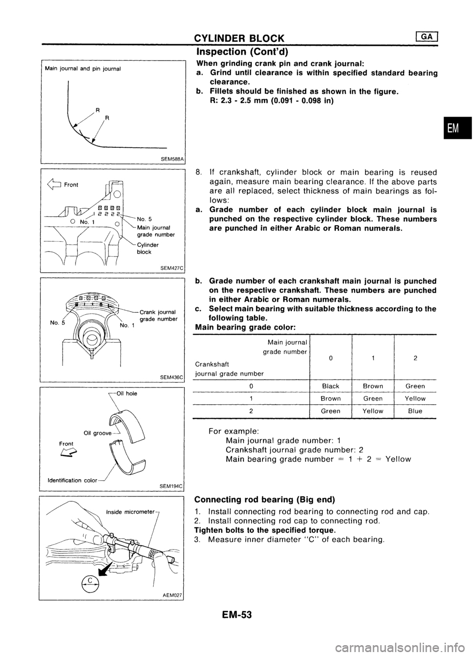
a. Grade number ofeach cylinder blockmainjournal is
punched onthe respective cylinderblock.These numbers
are punched ineither Arabic orRoman numerals.
b. Grade number ofeach crankshaft mainjournal ispunched
on the respective crankshaft. Thesenumbers arepunched
in either Arabic orRoman numerals.
c. Select mainbearing withsuitable thickness according tothe
following table.
Main bearing gradecolor:
Main journal
grade number
0
1
2
Crankshaft
journal gradenumber
0
Black
Brown Green
1
BrownGreenYellow
2
GreenYellow Blue
Crank
journal
grade number
SEM436C
\i1hOle
o,.",,!f0
Front ~~
Q
I\}:J
Identification color~
SEM194C
For
example:
Main journal gradenumber: 1
Crankshaft journalgradenumber: 2
Main bearing gradenumber
=
1
+
2 Yellow
)=====
.-:::::::======_ ..
;::..----
AEM027Connecting
rodbearing (Bigend)
1. Install connecting rodbearing toconnecting rodand cap.
2. Install connecting rodcap toconnecting rod.
Tighten boltstothe specified torque.
3. Measure innerdiameter "C"ofeach bearing.
EM-53
Page 1236 of 1701

IdentificationNo.
\ca
p
\
NO.1
t.:?
Enginefront
SEM420C CYLINDER
BLOCK
Assembly (Cont'd)
•
Front
Pistonringcompressor
SEM293C
2.
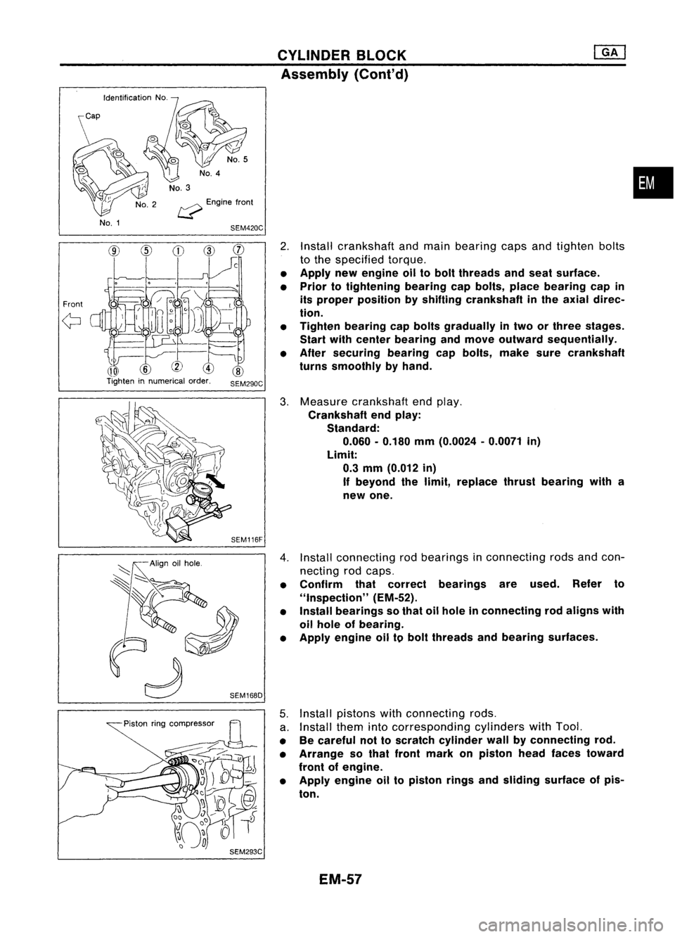
Install crankshaft andmain bearing capsandtighten bolts
to the specified torque.
• Apply newengine oiltobolt threads andseat surface.
• Prior totightening bearingcapbolts, placebearing capin
its proper position byshifting crankshaft inthe axial direc-
tion.
• Tighten bearing capbolts gradually intwo orthree stages.
Start withcenter bearing andmove outward sequentially.
• After securing bearingcapbolts, makesurecrankshaft
turns smoothly byhand.
3. Measure crankshaft endplay.
Crankshaft endplay:
Standard:
0.060 -0.180 mm(0.0024 -0.0071 in)
Limit: 0.3 mm (0.012 in)
If beyond thelimit, replace thrustbearing witha
new one.
4. Install connecting rodbearings inconnecting rodsandcon-
necting rodcaps.
• Confirm thatcorrect bearings areused. Referto
"Inspection" (EM-52).
• Install bearings sothat oilhole inconnecting rodaligns with
oil hole ofbearing.
• Apply engine oiltobolt threads andbearing surfaces.
5. Install pistons withconnecting rods.
a. Install themintocorresponding cylinderswithTool.
• Becareful nottoscratch cylinder wallbyconnecting rod.
• Arrange sothat front mark onpiston headfaces toward
front ofengine.
• Apply engine oiltopiston ringsandsliding surface ofpis-
ton.
EM-57
Page 1237 of 1701
Rearoilseal retainer
SEM736DCYLINDER
BLOCK
[ill
Assembly (Cont'd)
b. Install connecting rodcaps.
Tighten connecting rodcap nuts tothe specified torque.
tD.J:
Connecting rodcap nuts
(1) Tighten to13.72 to15.68 N'm(1.399 to1.599
kg-m, 10.120 to11.566 ft-Ib).
(2) Turn nutsto35° to40° degrees clockwise withan
angle wrench. Ifan angle wrench isnot avail-
able tighten nutsto23 to28 N'm (2.3to2.9 kg-m,
17 to21 ft-Ib).
6. Measure connecting rodside clearance.
Connecting rodside clearance:
Standard:
0.200 -0.470 mm(0.0079 -0.0185 in)
limit:
0.52 mm(0.0205 in)
If beyond thelimit, replace connecting rod
and/or crankshaft.
7. Install rearoilseal retainer.
a. Before installing rearoilseal retainer, removealltraces of
liquid gasket fromcylinder blockandretainer witha
scraper.
b. Apply acontinuous beadofliquid gasket torear oilseal
retainer.
• Apply around innersideofbolt holes.
EM-58
Page 1245 of 1701
SEM050D
Cut here.
~ 7mm (0.28 In)
liquid gasket
---j.~
oruu
Groove Bolthole
SEM357E
SEM065D OIL
PAN
Installation
1. Install aluminum oilpan.
a. Use ascraper toremove alltraces ofliquid gasket from
mating surfaces.
• Also remove tracesofliquid gasket frommating surface of
cylinder blockandfront cover.
b. Apply acontinuous beadofliquid gasket tomating surface
of aluminum oilpan.
• Use Genuine LiquidGasket orequivalent.
• Besure liquid gasket diameter is4.0 to5.0 mm (0.157 to
0.197 in).
• Attaching shouldbedone within 5minutes aftercoating.
• For areas marked with
"*",
apply liquid gasket tothe outer
side ofthe bolt hole.
c. Install aluminum oilpan.
• Install boltsinthe reverse orderofremoval.
CD •
@)
bolts:
~: 16-19 N'm (1.6-1.9 kg-m, 12-14 ft-Ib)
@,
@
bolts:
~: 6.4-7.5 N'm (0.65 •0.76 kg-m, 56.4-66.0 in-Ib)
2. Install thetwo engine totransaxle bolts.
For tightening torque,refertoMT orAT section ("REMOVAL
AND INSTALLATION").
3. Install rearcover plate.
EM-66
Page 1256 of 1701
MethodA
Method B 90+5degrees
-0
Engine Paint
mark
front
:0
118
~
(12,87)
Plasticzone
EO
78
0,
(8,58)
~
E
39
z
(4,29)
SEM074DATIMING
CHAIN
[]B]
Installation (Cont'd)
@
Method A:Turn allbolts 90to95 degrees clockwise with
Tool orsuitable anglewrench.
Method B:
If
angle wrench isnot available, dothe follow-
ing. Mark theside ofall bolts withpaint marks
facing thefront ofthe engine. Thenturnthem 90
to 95 degrees clockwise.
CD
Turn allbolts 90to95 degrees clockwise. •
@
Ensure thatpaint mark oneach boltfaces therear ofthe
engine. (Method Bonly)
Do not turn anybolt 180to190 degrees clockwise allatonce.
Tightening torqueN'm(kg-m, ft-Ib)
@
39(4.0, 29)
@
78(8.0, 58)
@
0(0,0)
@
34-44 (3.5 -4.5, 25-33)
@
90-95 degrees (90degree preferred)
CD
90
-95 degrees (90degree preferred)
14. Install cylinder headoutside bolts.
15. Install thefollowing waterhoses.
• Water hoseforcylinder block.
• Water hosesforheater.
16. Install knocksensor harness connector.
EM-77