Page 1508 of 1701
ENGINEMAINTENANCE ~
Checking CoolingSystem(Cont'd)
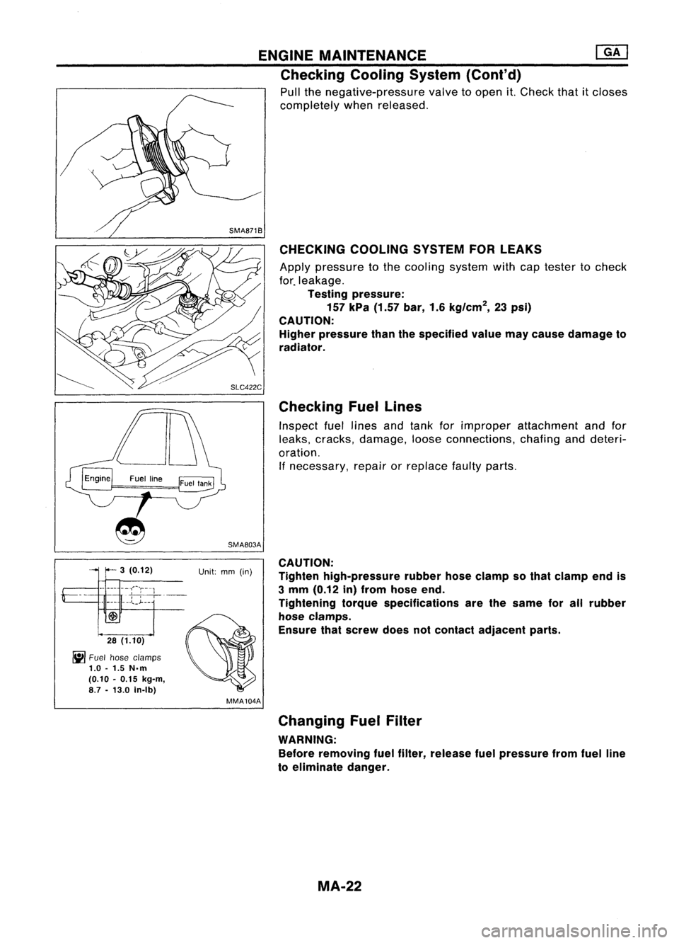
Pull thenegative-pressure valvetoopen it.Check thatitcloses
completely whenreleased.
SMA871B CHECKING COOLINGSYSTEMFORLEAKS
Apply pressure tothe cooling systemwithcaptester tocheck
for. leakage.
Testing pressure:
157 kPa (1.57 bar,1.6kg/cm
2,
23psi)
CAUTION: Higher pressure thanthespecified valuemaycause damage to
radiator.
Checking Fuellines
Inspect fuellines andtank forimproper attachment andfor
leaks, cracks, damage, looseconnections, chafinganddeteri-
oration. If necessary, repairorreplace faultyparts.
SMA803A
3 (0.12) Unit:mm(in)
-- --- ----,;~-r--1
"
,
-,-,-,
~-
_______ .J",_~__
28 (1.10)
~ Fuel hose clamps
1.0 -1.5 N.m
(0.10 -0.15 kg-m,
8.7 -13.0 in-Ib)
MMA104ACAUTION:
Tighten high-pressure rubberhoseclamp sothat clamp endis
3 mm (0.12 in)from hose end.
Tightening torquespecifications arethesame forallrubber
hose clamps.
Ensure thatscrew doesnotcontact adjacent parts.
Changing FuelFilter
WARNING: Before removing fuelfilter, release fuelpressure fromfuelline
to eliminate danger.
MA-22
Page 1518 of 1701
![NISSAN ALMERA N15 1995 Service Manual ENGINEMAINTENANCE [][]
Checking CoolingSystem(Cont'd)
Pull thenegative-pressure valvetoopen it.Check thatitcloses
completely whenreleased.
CHECKING COOLINGSYSTEMFORLEAKS
Apply pressure tothe c NISSAN ALMERA N15 1995 Service Manual ENGINEMAINTENANCE [][]
Checking CoolingSystem(Cont'd)
Pull thenegative-pressure valvetoopen it.Check thatitcloses
completely whenreleased.
CHECKING COOLINGSYSTEMFORLEAKS
Apply pressure tothe c](/manual-img/5/57349/w960_57349-1517.png)
ENGINEMAINTENANCE [][]
Checking CoolingSystem(Cont'd)
Pull thenegative-pressure valvetoopen it.Check thatitcloses
completely whenreleased.
CHECKING COOLINGSYSTEMFORLEAKS
Apply pressure tothe cooling systemwithcaptester tocheck
f~r leakage.
Testing pressure:
157 kPa (1.57 bar,1.6kg/cm
2,
23psi)
CAUTION:
Higher pressure thanthespecified valuemaycause damage to
radiator.
SMA811C
SMA803A
Checking
FuelLines
Inspect fuellines andtank forimproper attachment, leaks,
cracks, damage, looseconnections, chafingordeterioration.
If necessary, repairorreplace faultyparts.
3 (0.12) Unit:mm(in)
_._-- --,"'~'r---1
"
,
-
-
---;--,
-,---
•• J..
_J- __
28 (1.10)
~ Fuel hose clamps
1.0 -1.5 N.m
(0.10 -0.15 kg-m,
8.7 -13.0 in-Ib)
MMA104A
• FUEL PRESRELEASE.
0
FUEL PUMP WILLSTOP BY
TOUCHING STARTDURING
IDLE_
CRANK AFEW TIMES AFTER
ENGINE STALL.
---S-T~-RT--
SEF823KCAUTION:
Tighten high-pressure rubberhoseclamp sothat clamp endis
3 mm (0.12 in)from hose end.
Tightening torquespecifications arethesame forallrubber
hose clamps.
Ensure thatscrew doesnotcontact adjacent parts.
Changing FuelFilter
WARNING:
Before removing fuelfilter, release fuelpressure fromfuelline
to eliminate danger.
rF.i\
1.Start engine.
~ 2.Perform "FUELPRESSURE RELEASE"in"WORK
SUPPORT" modewithCONSULT.
3. After engine stalls,crankengine twoorthree times
to make surethatfuel pressure isreleased.
4. Turn ignition switchoff.
MA-32
Page 1524 of 1701
ENGINEMAINTENANCE
Air conditioner
compressor
SMA442C
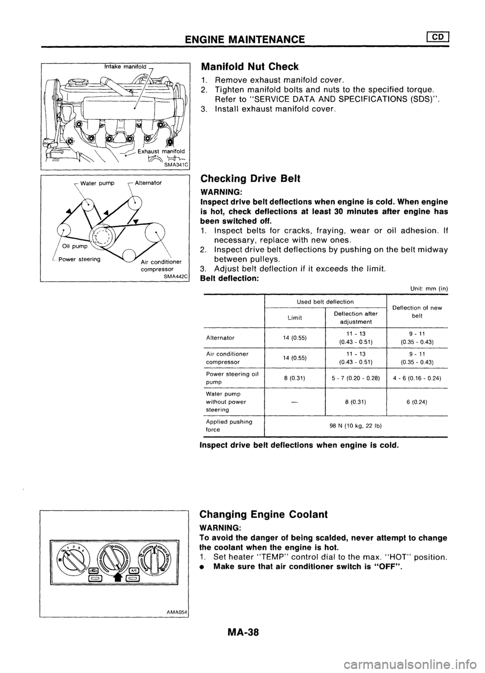
AMA054 Manifold
NutCheck
1. Remove exhaustmanifold cover.
2. Tighten manifold boltsandnuts tothe specified torque.
Refer to"SERVICE DATAANDSPECIFICATIONS (SOS)".
3. Install exhaust manifold cover.
Checking DriveBelt
WARNING:
Inspect drivebeltdeflections whenengine iscold. When engine
is hot, check deflections atleast 30minutes afterengine has
been switched off.
1. Inspect beltsforcracks, fraying, wearoroil adhesion. If
necessary, replacewithnewones.
2. Inspect drivebeltdeflections bypushing onthe belt midway
between pulleys.
3. Adjust belt
deflection
if
it
exceeds thelimit.
Belt deflection:
Unit:mm(in)
Used beltdeflection
Deflectionofnew
Limit Deflection
after
belt
adjustment
Alternator 14(0.55) 11
-13 9-11
(0.43 -051) (0.35-0.43)
Air conditioner
14(0.55) 11
-13
9-11
compressor (0.43-051) (0.35-0.43)
Power steering oil
8(0.31) 5-7 (0.20 -0.28) 4-6 (0.16 -0.24)
pump
Water pump
without power
-
8(0.31) 6(0.24)
steering
Applied pushing
98N(10 kg,22Ib)
force
Inspect drivebeltdeflections whenengine iscold.
Changing EngineCoolant
WARNING:
To avoid thedanger ofbeing scalded, neverattempt tochange
the coolant whentheengine ishot.
1. Set heater "TEMP" controldialtothe max. "HOT" position.
• Make surethatairconditioner switchis"OFF".
MA-38
Page 1533 of 1701
CHASSISANDBODY MAINTENANCE
OK MINMax,
line
Min, line
SBR418C Changing
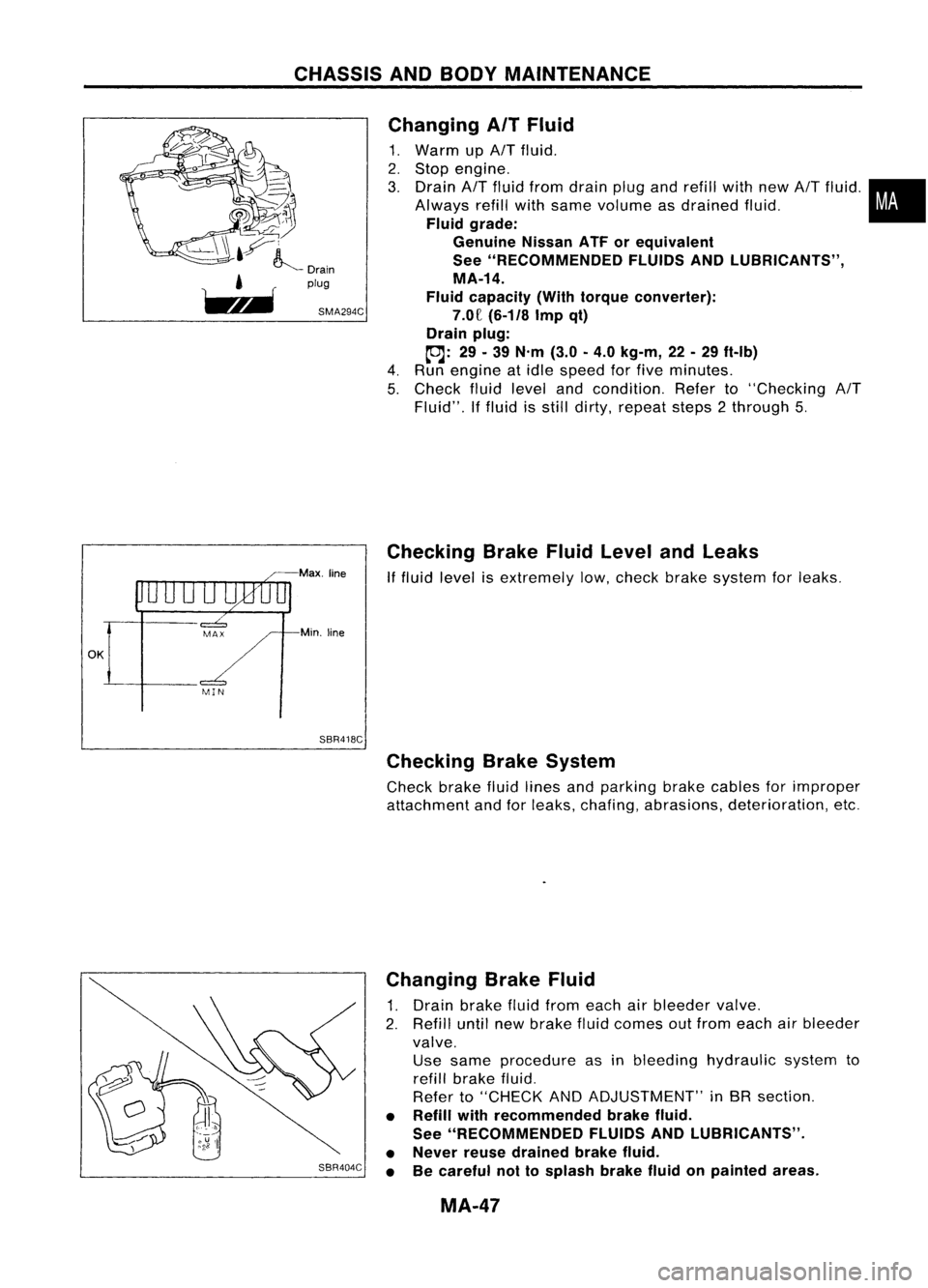
AITFluid
1. Warm up
AIT
fluid.
2. Stop engine.
3. Drain
AIT
fluid from drain plugandrefill withnew
AIT
fluid .•
Always refillwithsame volume asdrained fluid.
i
Fluid grade:
Genuine NissanATForequivalent
See "RECOMMENDED FLUIDSANDlUBRICANTS",
MA-14.
Fluid capacity (Withtorque converter):
7.0£
(6-1/8
Impqt)
Drain plug:
toJ:
29.39
N'm
(3.0-4.0
kg-m,
22-29
ft-Ib)
4. Run engine atidle speed forfive minutes.
5. Check fluidlevel andcondition. Referto"Checking
AIT
Fluid". Iffluid isstill dirty, repeat steps2through 5.
Checking BrakeFluidLevel andLeaks
If
fluid level isextremely low,check brakesystem forleaks.
Checking BrakeSystem
Check brakefluidlines andparking brakecables forimproper
attachment andforleaks, chafing, abrasions, deterioration, etc.
SBR404C Changing
BrakeFluid
1. Drain brake fluidfrom each airbleeder valve.
2. Refill untilnewbrake fluidcomes outfrom each airbleeder
valve. Use same procedure asinbleeding hydraulic systemto
refill brake fluid.
Refer to"CHECK ANDADJUSTMENT" inBR section.
• Refill withrecommended brakefluid.
See "RECOMMENDED FLUIDSANDlUBRICANTS".
• Never reusedrained brakefluid.
• Becareful nottosplash brakefluidonpainted areas.
MA-47
Page 1536 of 1701
0
0
•
0
0
~ /0
H
H
0
0
(2)
4wheels
5 wheels
SMA785C
Radial
tires
CHASSIS
ANDBODY MAINTENANCE
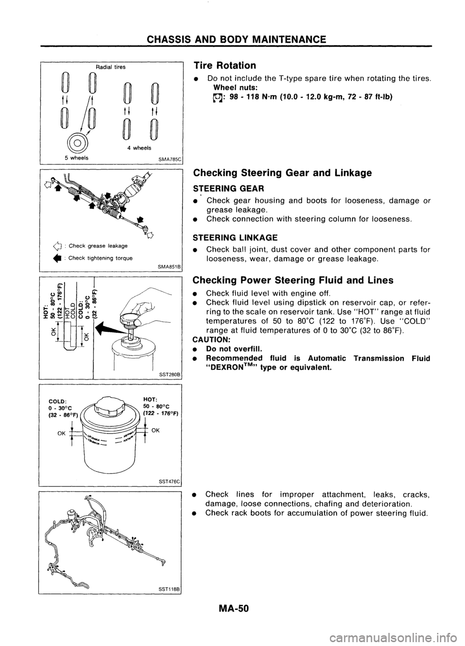
Tire Rotation
Do not include theT-type sparetirewhen rotating thetires .
Wheel nuts:
~: 98-118 N'm (10.0 -12.0 kg-m, 72-87 ft-Ib)
Q :
Check grease leakage
• :Check tightening torque
Checking
SteeringGearandLinkage
STEERING GEAR
• Check gearhousing andboots forlooseness, damageor
grease leakage.
• Check connection withsteering columnforlooseness.
STEERING LINKAGE
• Check balljoint, dustcover andother component partsfor
looseness, wear,damage orgrease leakage.
SMA851B
Checking PowerSteering FluidandLines
• Check fluidlevel withengine off.
• Check fluidlevel using dipstick onreservoir cap,orrefer-
ring tothe scale onreservoir tank.Use"HOT" rangeatfluid
temperatures of50 to80°C (122to176°F). Use"COLD"
range atfluid temperatures of
a
to 30°C (32to86°F).
CAUTION:
• Donot overfill.
• Recommended fluidisAutomatic Transmission Fluid
''DEXRON™,, typeorequivalent.
SST280B
SST476C
•Check linesforimproper attachment, leaks,cracks,
damage, looseconnections, chafinganddeterioration.
• Check rackboots foraccumulation ofpower steering fluid.
MA-50
Page 1541 of 1701
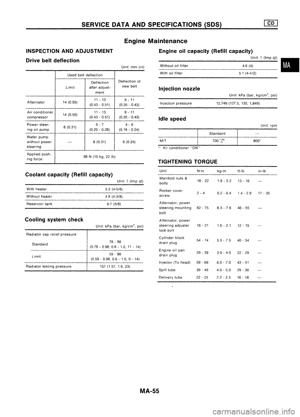
SERVICEDATAANDSPECIFICATIONS (50S)
Used beltdeflection
Deflection Deflection
of
Limit afteradjust- new
belt
ment
Alternator 14(055) 11
-13 9-11
(0.43 -0.51)
(0.35-0.43)
Air conditioner
14(0.55) 11
-13
9-11
compressor (0.43
-0.51)
(0.35-0.43)
Power steer-
8(0.31) 5
-7
4-6
ing oilpump (0.20-0.28)
(0.16-0.24)
Water pump
without power
-
8
(0.31) 6(0.24)
steering
Applied push-
98N(10 kg, 22Ib)
ing force
Coolant capacity (Refillcapacity)
INSPECTION
ANDADJUSTMENT
Drive beltdeflection
Unit:kPa(bar, kg/cm', psi)
12,749 (127.5, 130,1,849)
Without
oilfilter
With oilfilter
Injection pressure
Injection
nozzle
Idle speed
Unit:rpm
Standard
M/T
700
'go
800'
': Air conditioner "ON"
TIGHTENING TORQUE
Unit N'mkg-m
ft-Ib in-Ib
Manifold nuts
&
18-22
1.8-2.2
bolts 13
-16
Rocker cover
2-4
0.2-0.4 1.4-2.9 17-35
screw
Alternator, power
steering mounting 62-75
6.3-76 46
-55
bolt
Alternator, power
steering adjuster 16
-21
1.6-2.1
12-15
lock bolt
Cylinder block
54-74
5.5-7.5 40
-54
drain plug
Engine oilpan
29-39 3.0-4.0 22-29
drain plug
Injector (Tohead)
59-69 6.0-7.0 43-51
Spill tube 39-49
4.0-5.0 29-36
Delivery tube 22-25 2.2-2.5
16-18
Engine
Maintenance
Engine oilcapacity (Refillcapacity)
Unit:[(Imp qt)•
46 (4)
51 (4--1/2)
Unit:
mm(in)
Unit:
f
(Imp qt)
5.2 (4-5/8)
49 (4-3/8)
0.7 (5/8)
Unit: kPa(bar, kg/cm', psi)
78 -98
(0.78 -0.98, 08-1.0, 11-14)
59 -98
(0.59 -0.98, 06-10, 9-14)
157 (1.57, 1.6,23)
Standard
Limit
With
heater
Without heater
Reservoir tank
Radiator caprelief pressure
Radiator testingpressure
Cooling
systemcheck
MA-55
Page 1544 of 1701
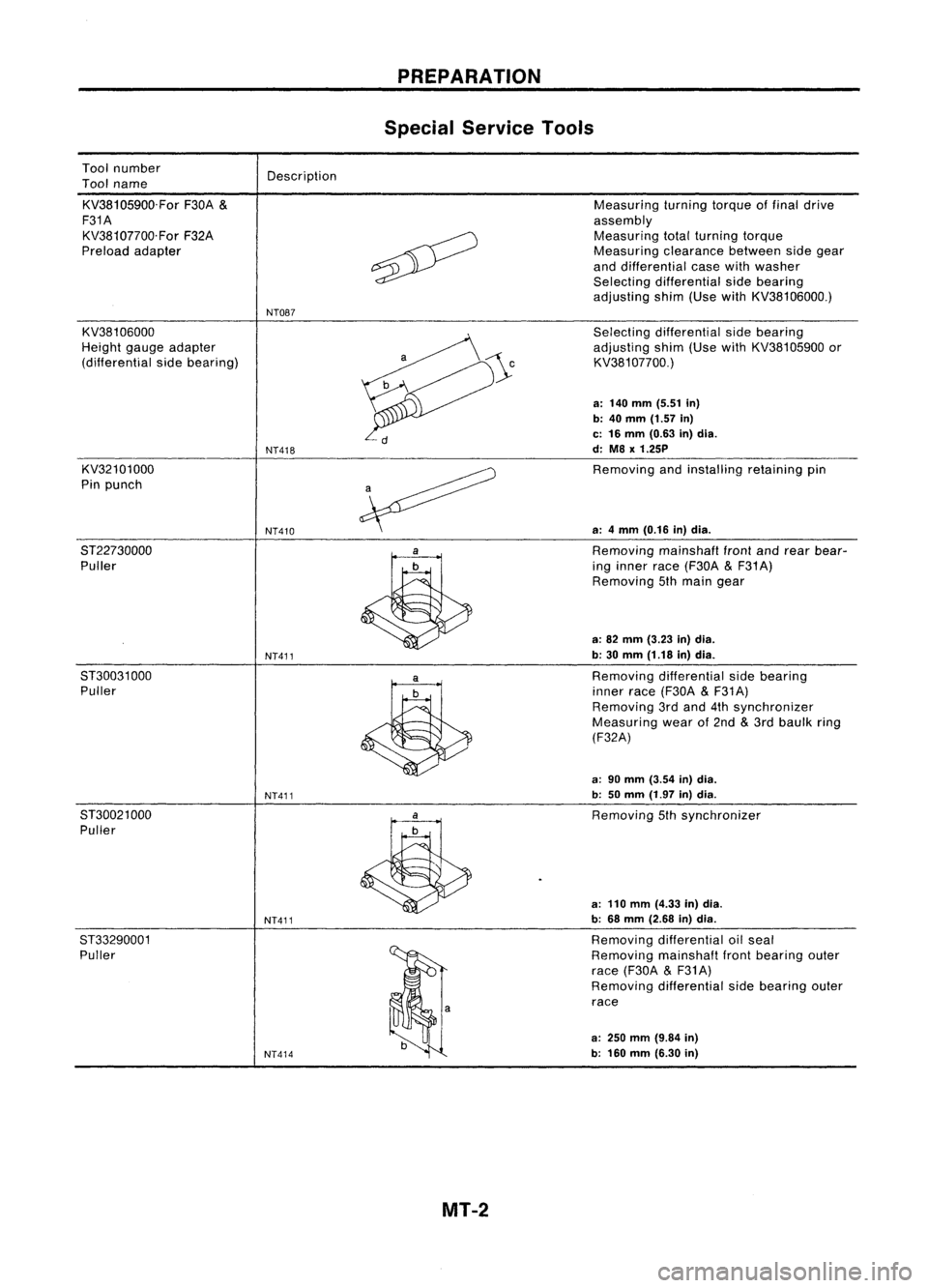
Toolnumber
Tool name
KV38105900.For F30A
&
F31A KV38107700.For F32A
Preload adapter Description
NT087 PREPARATION
Special Service Tools
Measuring turningtorqueoffinal drive
assembly Measuring totalturning torque
Measuring clearancebetweensidegear
and differential casewithwasher
Selecting differential sidebearing
adjusting shim(UsewithKV38106000.)
KV38106000
Height gaugeadapter
(differential sidebearing)
KV32101000
Pin punch
8T22730000 Puller
8T30031 000
Puller
8T30021 000
Puller
ST33290001 Puller
NT418
NT410
NT411
NT411
NT411
NT414
Selecting
differential sidebearing
adjusting shim(UsewithKV38105900 or
KV381 07700.)
a: 140 mm (5.51 in)
b: 40
mm
(1.57
in)
c: 16 mm (0.63 in)dia.
d: M8
x
1.25P
Removing andinstalling retainingpin
a: 4mm (0.16 in)dia.
Removing mainshafl
front
andrear bear-
ing inner race(F30A
&
F31 A)
Removing 5thmain gear
a: 82 mm (3.23 in)dia.
b: 30 mm (1.18 in)dia.
Removing differential sidebearing
inner race(F30A
&
F31A)
Removing 3rdand 4thsynchronizer
Measuring wearof2nd
&
3rd baulk ring
(F32A)
a: 90 mm (3.54 in)dia.
b: 50mm (1.97 in)dia.
Removing 5thsynchronizer
a: 110 mm (4.33 in)dia.
b: 68 mm (2.68 in)dia.
Removing differential oilseal
Removing mainshaflfrontbearing outer
race (F30A
&
F31A)
Removing differential sidebearing outer
race
a:
250
mm
(9.84
in)
b: 160 mm (6.30 in)
MT-2
Page 1550 of 1701
@
M/T
toengine
CD
REMOVAL
ANDINSTAllATION
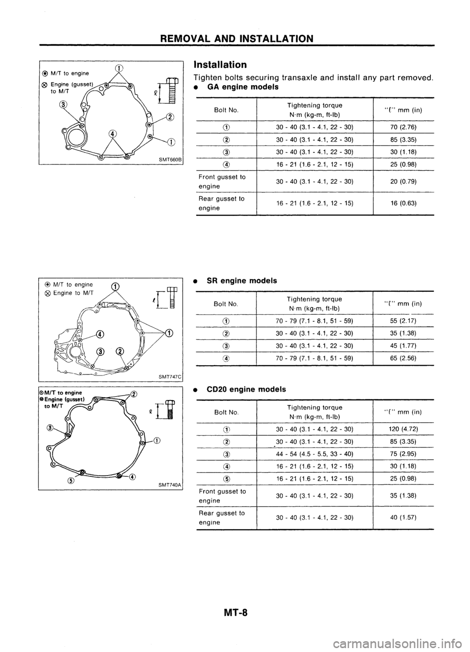
Installation
Tighten boltssecuring transaxle andinstall anypart removed.
• GA engine models
Bolt No. Tightening
torque
"C"mm (in)
N'm (kg-m, ft-Ib)
G) 30-40 (3.1 -4.1,22 -30) 70
(2.76)
@ 30-40 (3.1 -4.1,22 -30) 85(3.35)
@
30-40 (3.1 -4.1, 22-30) 30(1.18)
@ 16-21 (1.6 -2.1,12 -15) 25(0.98)
Front gusset to
30-40 (3.1 -4.1,22 -30) 20(0.79)
engine
Rear gusset to
16-21 (1.6 -2.1,12 -15) 16
(0.63)
engine
@
M/T
toengine ~
Q9
Engine toM/T
leV
~o". Q~.\
17
SMT747C
CD
SMT740A •
SRengine models
Bolt No. Tightening
torque
"C"mm (in)
N'm (kg-m, ft-Ib)
--
G)
70-79 (7.1 -8.1,51 -59) 55
(2.17)
@
30-40 (3.1 -4.1,22 -30) 35
(1.38)
@
30-40 (3.1 -4.1,22 -30) 45
(1.77)
@ 70-79 (7.1 -8.1,51 -59) 65
(2.56)
• CD20 engine models
Boll No. Tightening
torque
"C"mm (in)
N'm (kg-m, ft-Ib)
G)
30
-40 (3.1 -4.1, 22-30) 120
(4.72)
@
30-40 (3.1 -4.1,22 -30) 85
(3.35)
@
44
-54 (4.5 -5.5, 33-40) 75
(2.95)
@
16-21 (1.6 -2.1,12 -15) 30
(1.18)
@
16-21 (1.6 -2.1,12 -15) 25
(0.98)
Front gusset to
30-40 (3.1 -4.1, 22-30) 35
(1.38)
engine
Rear gusset to
30-40 (3.1 -4.1, 22-30) 40
(1.57)
engine
MT-8