Page 1258 of 1701
•
TIMING
CHAIN
Installation (Cont'd)
• Tightening procedure
STEP 1:
RH camshaft
Tighten bolts
@-
@l
inthat order then
tighten bolts
CD-
@
inthat order.
~: 2N'm (0.2kg-m, 1.4ft-Ib)
LH camshaft
Tighten bolts
@-
@
inthat order then
tighten bolts
CD-
@l
inthat order.
~: 2N'm (0.2kg-m, 1.4ft-Ib)
STEP 2:
Tighten boltsinthe specified order.
~: 6N'm (0.6kg-m, 4.3ft-Ib)
STEP 3:
Tighten boltsinthe specified order.
Bolt type
@
CID CID ~
(f)
~: 9.8-11.8 N'm
(1.0 -1.2 kg-m, 7.2-8.7 ft-Ib)
Bolt type
@
~: 18-25 N'm
(1.8 -2.6 kg-m, 13-19 ft-Ib)
21. Install camshaft sprockets.
Line upmating marksontiming chainwithmating markson
camshaft sprockets.
SEM987CA
, "--_ ../ / I
SEM696DA
LH
camshaft
Tighten innumerical order.
~ Engine front
•Lock camshafts asshown infigure andtighten tospecified
torque.
~: 137-157 N'm
(14.0 -16.0 kg-m, 101-116 ft-Ib)
Apply engine oiltothreads andseating surfaces ofcamshaft
sprocket boltsbefore installing them.
SEM584D
22.Install timing chainguide.
EM-79
Page 1268 of 1701

SEM929CCYLINDER
HEAD ~
Inspection (Cont'd)
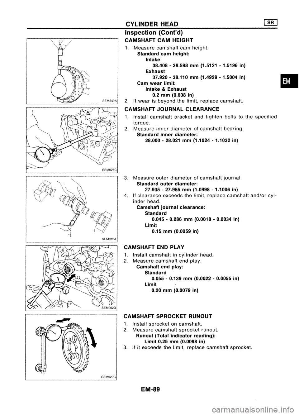
CAMSHAFT CAMHEIGHT
1. Measure camshaft camheight.
Standard camheight:
Intake 38.408 -38.598 mm(1.5121 .1.5196 in)
Exhaust 37.920 •38.110 mm(1.4929. 1.5004in)
Cam wear limit:
Intake
&
Exhaust
0.2 mm (0.008 in)
2. Ifwear isbeyond thelimit, replace camshaft.
CAMSHAFT JOURNALCLEARANCE
1. Install camshaft bracketandtighten boltstothe specified
torque.
2. Measure innerdiameter ofcamshaft bearing.
Standard innerdiameter:
28.000 -28.021 mm(1.1024 -1.1032 in)
Measure outerdiameter ofcamshaft journal.
Standard outerdiameter:
27.935 .27.955 mm(1.0998 -1.1006 in)
If clearance exceedsthelimit, replace camshaft and/orcyl-
inder head.
Camshaft journalclearance:
Standard 0.045 -0.086 mm(0.0018 .0.0034 in)
Limit 0.15 mm(0.0059 in)
CAMSHAFT ENDPLAY
1. Install camshaft incylinder head.
2. Measure camshaft endplay.
Camshaft endplay:
Standard 0.055. 0.139mm(0.0022 -0.0055 in)
Limit 0.20 mm(0.0079 in)
CAMSHAFT SPROCKETRUNOUT
1. Install sprocket oncamshaft.
2. Measure camshaft sprocketrunout.
Runout (Totalindicator reading):
Limit 0.25mm(0.0098 in)
3. Ifitexceeds thelimit, replace camshaft sprocket.
EM-89
•
Page 1284 of 1701

AB
Taper:A-B
Out-at-round: X-
y
y
SEM316A CYLINDER
BLOCK ~
Inspection (Cont'd)
6. Cylinder boresizeisdetermined byadding piston-to-bore
clearance topiston diameter "A".
Rebored sizecalculation:
D=A+B-C where,
D: Bored diameter
A: Piston diameter asmeasured •
B: Piston-to-bore clearance
C: Honing allowance 0.02mm(0.0008 in)
7. Install mainbearing caps,andtighten tothe specified
torque.
• Otherwise, cylinderboresmaybedistorted infinal assem-
bly.
8. Cut cylinder bores.
• When anycylinder needsboring, allother cylinders must
also bebored.
• Donot cuttoo much outofcylinder boreatatime. Cutonly
0.05 mm(0.0020 in)orso indiameter atatime.
9. Hone cylinders toobtain specified piston-to-bore clearance.
10. Measure finishedcylinder boreforout-of-round andtaper.
• Measurement shouldbedone aftercylinder borecools
down.
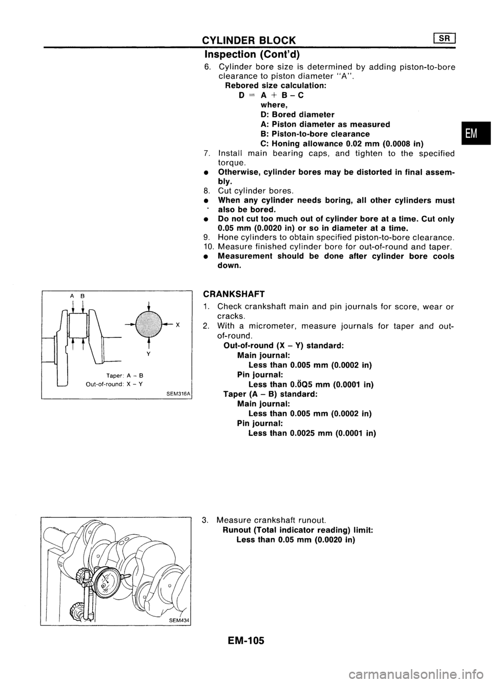
CRANKSHAFT
1. Check crankshaft mainandpinjournals forscore, wearor
cracks.
2. With amicrometer, measurejournalsfortaper andout-
of-round.
Out-of-round (X-Y) standard:
Main journal:
Less than0.005 mm(0.0002 in)
Pin journal:
Less than0.005 mm(0.0001 in)
Taper (A-B) standard:
Main journal:
Less than0.005 mm(0.0002 in)
Pin journal:
Less than0.0025 mm(0.0001 in)
3. Measure crankshaft runout.
Runout (Totalindicator reading)limit:
Less than0.05mm(0.0020 in)
EM-105
Page 1286 of 1701

Crankshaft
front view
Crankshaft
front view
•
Crankshaft
Cylinderblockmainjournal gradenumber
main journal
grade num-
0 12
3
ber
012
3
0
(A,Black) (B,
Brown) (C,
Green) (0,Yellow)
.
12
3
4
1
(B,Brown) (C,Green) (0,
Yellow) (E,Blue)
2
3
4
5
2
(C,Green) (0,
Yellow) (E,Blue) (F,Pink)
3
4
5
6
3
(0,Yellow) (E,
Blue) (F,
Pink) (G,Nocolor)
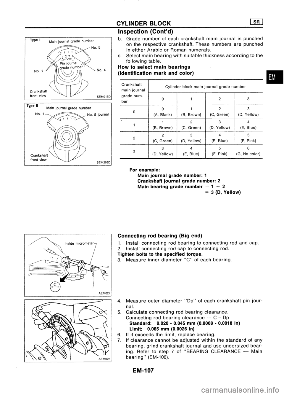
For example:
Main journal gradenumber: 1
Crankshaft journalgradenumber: 2
Main bearing gradenumber =1+ 2
=
3(D, Yellow)
CYLINDER
BLOCK ~
Inspection (Conl'd)
b. Grade number ofeach crankshaft mainjournal ispunched
on the respective crankshaft. Thesenumbers arepunched
in either Arabic orRoman numerals.
c. Select mainbearing withsuitable thickness according tothe
following table.
How toselect mainbearings
(Identification markandcolor)
SEM013D No.
4
SEM203D
Main
journal gradenumber
No.5
Main journal gradenumber
NO.1
Type
I
No.1
Type II
Connectingrodbearing (Bigend)
1. Install connecting rodbearing toconnecting rodand cap.
2. Install connecting rodcap toconnecting rod.
Tighten boltstothe specified torque.
3. Measure innerdiameter "C"ofeach bearing.
4. Measure outerdiameter "Dp"ofeach crankshaft pinjour-
nal.
5. Calculate connecting rodbearing clearance.
Connecting rodbearing clearance
=
C-Dp
Standard:
0.020.0.045
mm
(0.0008 .0.0018
in)
Limit:
0.065
mm
(0.0026
in)
6. Ifitexceeds thelimit, replace bearing.
7.
If
clearance cannotbeadjusted withinthestandard ofany
bearing, grindcrankshaft journalanduseundersized bear-
ing. Refer tostep 7of "BEARING CLEARANCE -Main
bearing" (EM-106).
EM-107
Page 1290 of 1701
![NISSAN ALMERA N15 1995 Service Manual Tighteninnumerical order.
'::::::-.... Alignoilhole.
~~
'~~-
SEM015D
SEM159B CYLINDER
BLOCK [][]
Assembly (Cont'd)
2. Install crankshaft andmain bearing capsandtighten bolts
to the spec NISSAN ALMERA N15 1995 Service Manual Tighteninnumerical order.
'::::::-.... Alignoilhole.
~~
'~~-
SEM015D
SEM159B CYLINDER
BLOCK [][]
Assembly (Cont'd)
2. Install crankshaft andmain bearing capsandtighten bolts
to the spec](/manual-img/5/57349/w960_57349-1289.png)
Tighteninnumerical order.
'::::::-.... Alignoilhole.
~~
'~~-
SEM015D
SEM159B CYLINDER
BLOCK [][]
Assembly (Cont'd)
2. Install crankshaft andmain bearing capsandtighten bolts
to the specified torque.
• Apply newengine oiltothread ofbearing capbolts.
• Prior totightening bearingcapbolts, shiftcrankshaft back
and forth toproperly seatthebearing cap.
• Tightening procedure
a. Tighten allbolts to26 to32 N'm (2.7to3.3 kg-m, 20to24 •
in-Ib).
b. Turn allbolts 75to80 degrees clockwise withTool orsuit-
able angle wrench.
c. Loosen allbolts completely.
d. Tighten allbolts to32 to38 N'm (3.3to3.9 kg-m, 24to28
ft-Ib).
e. Turn allbolts 45to50 degrees clockwise withTool orsuit-
able angle wrench.
• Ifan angle wrench isnot available, markallbearing cap
bolts onthe side facing engine rear.Then, turneach bolt
specified degreesclockwise. Confirmangleofdegrees with
a graduator, notbyeye-measurement.
• After securing bearingcapbolts, makesurecrankshaft
turns smoothly byhand.
3. Measure crankshaft endplay.
Crankshaft endplay:
Standard
0.10 -0.26 mm(0.0039 -0.0102 in)
Limit
0.30 mm(0.0118 in)
If beyond thelimit, replace thrustbearings withnewones.
4. Install connecting rodbearings inconnecting rodsandcon-
necting rodcaps.
• Confirm thatcorrect bearings areused. Referto
"I nspection" .
• Install bearings sothat oilhole inconnecting rodaligns with
oil hole ofbearing.
• Apply newengine oiltobolt threads andbearing surfaces.
5. Install pistons withconnecting rods.
a. Install themintocorresponding cylinderswithTool.
• Becareful nottoscratch cylinder wallbyconnecting rod.
• Arrange sothat front mark onpiston headfaces toward
front ofengine.
• Apply newengine oiltopiston ringsandsliding surface of
piston.
EM-111
Page 1291 of 1701
Connectingrodcap nut
SEM017D
SEM218D
SEM219D CYLINDER
BLOCK ~
Assembly (Cont'd)
b. Install connecting rodcaps.
Tighten connecting rodcap nuts tothe specified torque.
Tightening procedure:
1) Tighten nutsto14 to16 N'm (1.4to1.6 kg-m, 10to
12 ft-Ib).
2) Turn nuts60to65 degrees clockwise with
angle wrench.
If
angle wrench isnot available,
tighten nutsto38 to44 N'm (3.9to4.5 kg-m, 28
to 33 ft-Ib).
6. Measure connecting rodside clearance.
Connecting rodside clearance:
Standard 0.20 -0.35 mm(0.0079 -0.0138 in)
Limit 0.50 mm(0.0197 in)
If
beyond thelimit, replace connecting rodand/or crank-
shaft.
7. Install rearoilseal retainer.
a. Before installing rearoilseal retainer, removealltraces of
liquid gasket frommating surface usingascraper.
• Also remove tracesofliquid gasket frommating surface of
cylinder block.
b. Apply acontinuous beadofliquid gasket tomating surface
of rear oilseal retainer.
• Use Genuine LiquidGasket orequivalent.
EM-112
Page 1302 of 1701
SEM558
SEM517D
SEM518D TIMING
BELT
[f[]
Camshaft TimingBelt(Cont'd)
Belt tensioner, tensionerspringandidler
1. Check belttensioner andidler forsmooth turning.
2. Check condition oftensioner spring.
Crankshaft sprocketandfront camshaft sprocket
Check teethforabnormal signs.
INSTALLATION
1. Install crankshaft sprocketplateincorrect direction.
2. Confirm thatNO.1 piston isset atTDC onitscompression
stroke. (TDCisindicated bycrankshaft pulleynotchwithout
painted mark.)
3. Install tensioner andreturn spring.
Temporarily tightenboltssothat tensioner isset atthe fully
outside position.
4. Install idlerandtighten bolttothe specified torque.
EM-123
•
Page 1313 of 1701

SEM724B
SEM720B
WKOO"'P;O
Notch
~~~ SEM721BCYLINDER
HEAD
Inspection (Cont'd)
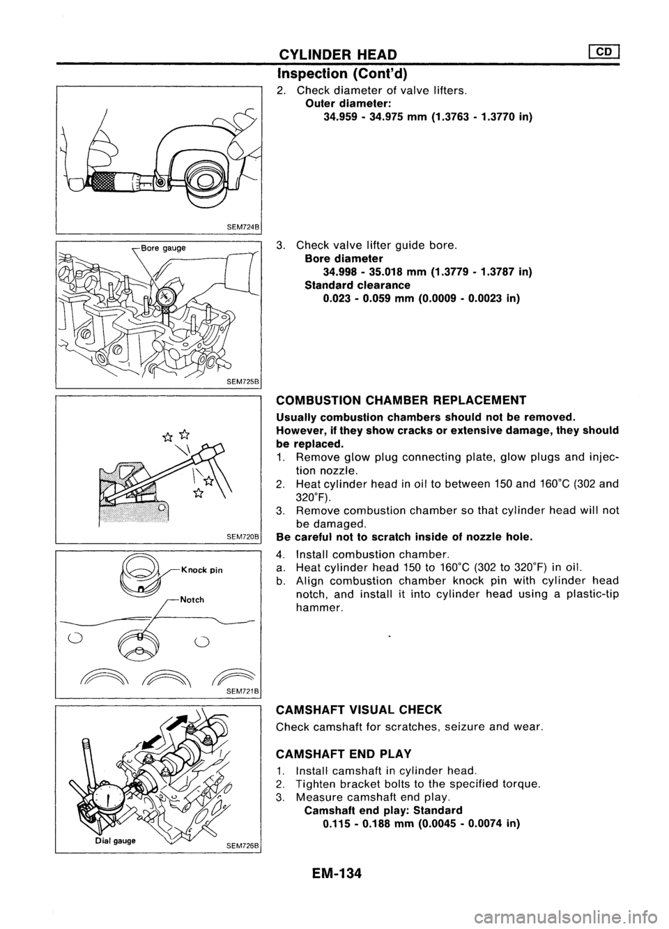
2. Check diameter ofvalve lifters.
Outer diameter:
34.959 -34.975 mm(1.3763 -1.3770 in)
3. Check valvelifterguide bore.
Bore diameter
34.998 -35.018 mm(1.3779 -1.3787 in)
Standard clearance
0.023 -0.059 mm(O.0009 -0.0023 in)
COMBUSTION CHAMBERREPLACEMENT
Usually combustion chambersshouldnotberemoved.
However, ifthey show cracks orextensive damage,theyshould
be replaced.
1. Remove glowplugconnecting plate,glowplugs andinjec-
tion nozzle.
2. Heat cylinder headinoil tobetween 150and 160°C (302and
320°F).
3. Remove combustion chambersothat cylinder headwillnot
be damaged.
Be careful nottoscratch insideofnozzle hole.
4. Install combustion chamber.
a. Heat cylinder head150to160°C (302to320°F) inoil.
b. Align combustion chamberknockpinwith cylinder head
notch, andinstall itinto cylinder headusing aplastic-tip
hammer.
CAMSHAFT VISUALCHECK
Check camshaft forscratches, seizureandwear.
CAMSHAFT ENDPLAY
1. Install camshaft incylinder head.
2. Tighten bracketboltstothe specified torque.
3. Measure camshaft endplay.
Camshaft endplay: Standard
0.115 -0.188 mm(O.0045 -0.0074 in)
EM-134