1995 NISSAN ALMERA N15 torque
[x] Cancel search: torquePage 687 of 1701
SMA525AON-VEHICLE
SERVICE
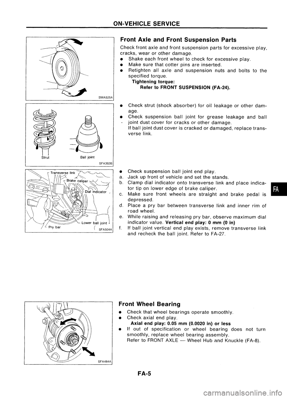
Front AxleandFront Suspension Parts
Check frontaxleandfront suspension partsforexcessive play,
cracks, wearorother damage.
• Shake eachfrontwheel tocheck forexcessive play.
• Make surethatcotter pinsareinserted.
• Retighten allaxle andsuspension nutsandbolts tothe
specified torque.
Tightening torque:
Refer toFRONT SUSPENSION (FA-24).
Strut
Ball
joint
SFA392B
•
Check strut(shock absorber) foroilleakage orother dam-
age.
• Check suspension balljoint forgrease leakage andball
joint dustcover forcracks orother damage.
If ball joint dustcover iscracked ordamaged, replacetrans-
verse link.
• Check suspension balljoint endplay.
a. Jack upfront ofvehicle andsetthe stands.
b. Clamp dialindicator ontotransverse linkand place indica- •
tor tiponlower edgeofbrake caliper. •
c. Make surefront wheels arestraight andbrake pedalis
depressed.
d. Place apry bar between transverse linkand inner rimof
road wheel.
e. While raising andreleasing prybar, observe maximum dial
indicator value.
Vertical endplay: 0mm (0in)
f. Ifball joint vertical endplay exists, remove transverse link
and recheck theball joint. Refer toFA-27.
SFA484A Front
Wheel Bearing
• Check thatwheel bearings operatesmoothly.
• Check axialendplay.
Axial endplay: 0.05mm(0.0020 in)orless
• If
out ofspecification orwheel bearing doesnotturn
smoothly, replacewheelbearing assembly.
Refer toFRONT AXLE-Wheel HubandKnuckle (FA-B).
FA-5
Page 689 of 1701
yf-\;
if
\mll//
Front
-----
A Inside
B: Outside
I
I
Lock
nut
SFA486A
SFA439B
SFA108A ON-VEHICLE
SERVICE
Front Wheel Alignment (Cont'd)
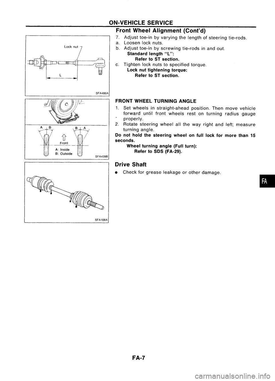
7. Adjust toe-inbyvarying thelength ofsteering tie-rods.
a. Loosen locknuts.
b. Adjust toe-inbyscrewing tie-rodsinand out.
Standard length
"L":
Refer toST section.
c. Tighten locknuts tospecified torque.
Lock nuttightening torque:
Refer toST section.
FRONT WHEEL TURNING ANGLE
1. Set wheels instraight-ahead position.Thenmove vehicle
forward untilfront wheels restonturning radiusgauge
properly.
2. Rotate steering wheelallthe way right andleft;measure
turning angle.
Do not hold thesteering wheelonfull lock formore than15
seconds.
Wheel turning angle(Fullturn):
Refer to50S (FA-29).
Drive Shaft
• Check forgrease leakage orother damage .
FA-7
•
Page 710 of 1701
,...............A
SFA858AFRONT
SUSPENSION
Transverse LinkandLower BallJoint (Cont'd)
INSPECTION
• Check transverse linkfordamage, cracksordeformation.
Replace ifnecessary.
• Check rubber bushing fordamage, cracksanddeformation.
Replace transverse linkifnecessary.
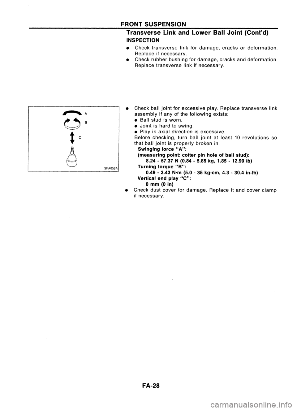
• Check balljoint forexcessive play.Replace transverse link
assembly ifany ofthe following exists:
• Ball stud isworn .
• Joint ishard toswing .
• Play inaxial direction isexcessive.
Before checking, turnballjoint atleast 10revolutions so
that balljoint isproperly brokenin.
Swinging force
"A":
(measuring point:cotter pinhole ofball stud):
8.24 -57.37 N(0.84 -5.85 kg,1.85 -12.90 Ib)
Turning torque
"B":
0.49 -3.43 N'm(5.0-35 kg-em, 4.3-30.4 in-Ib)
Vertical endplay
"e":
o
mm (0in)
• Check dustcover fordamage. Replaceitand cover clamp
if necessary.
FA-28
Page 712 of 1701
SERVICEDATAANDSPECIFICATIONS (SDS)
Inspection andAdjustment (Cont'd)
Nissan genuine greaseorequivalent
g
(oz)
Grease
Capacity
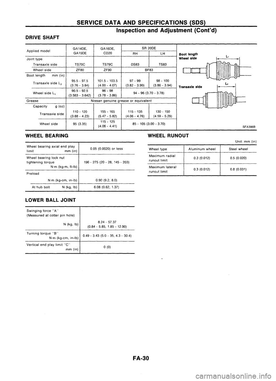
DRIVE
SHAFT
GA14DE,GA16DE, SA
20DE
Applied model
GA15DECD20
AHLH
Bootlength
Joint type
Wheel
side
Transaxle side TS70C TS79C
DS83TS83
Wheel side ZF80ZF90 BF83
Boot length mm(in)
Transaxle sideL
2
95.5
-97.5 101.5-103.5 97
-99 98-100
(376 -3.84) (4.00-4.07) (3.82-3.90) (3.86-3.94)
Transaxle side
Wheel sideL, 90.5
-92.5 96-98
94-96 (3.70 -3.78)
(3.563 -3.642) (3.78
-3.86)
85-105 (3.00 -3.70)
Transaxle
side
Wheel side 110
-120
(388 -4.23)
95 (3.35) 155
-165
(5.47 -5.82)
115 -125
(4.06 -4.41) 115
-135
(4.06 -4.76) 130
-150
(4.59 -5.29)
SFA3968
WHEEL BEARING WHEEL
RUNOUT
Unit:mm(in)
Wheel bearing axialendplay
limit mm(in)
Wheel bearing locknut
tightening torque
N'm (kg-m, ft-Ib)
Preload 0.05
(0.0020) orless
196 -275 (20-28, 145 -203) Wheel
type Aluminum
wheel Steelwheel
Maximum radial
0.3(0.012) 0.5(0.020)
runout limit
Maximum lateral
03(0.012) 0.8(0.031)
runout limit
N'm (kg-em, in-Ib)
At hub bolt
N
(kg, Ib)
0.90
(9.2, 8.0)
6.08 (0.62, 1.37)
LOWER BALLJOINT
Swinging force"A"
(Measured atcotter pinhole)
N (kg, Ib)
8.24
-5737
(0.84 -5.85, 1.85-12.90)
Turning torque"B"
Nm (kg-em, in-Ib)
Vertical endplay limit "C"
mm (in)
0.49
-3.43 (5.0-35, 4.3 -30.4)
0(0)
FA-30
Page 716 of 1701
Connector
/
SFE145A
t2Front
SFE366AFUEL
SYSTEM
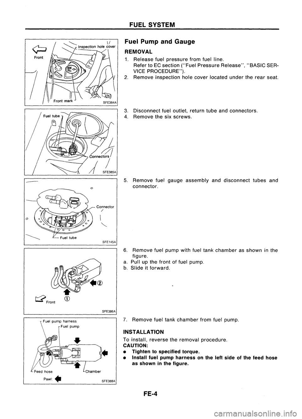
Fuel Pump andGauge
REMOVAL
1. Release fuelpressure fromfuelline.
Refer toEC section ("FuelPressure Release", "BASICSER-
VICE PROCEDURE").
2. Remove inspection holecover located undertherear seat.
3. Disconnect fueloutlet, returntubeandconnectors.
4. Remove thesixscrews.
5. Remove fuelgauge assembly anddisconnect tubesand
connector.
6. Remove fuelpump withfueltank chamber asshown inthe
figure.
a. Pull upthe front offuel pump.
b. Slide itforward.
Fuel pump harness
Fuel pump
SFE366A
7.
Remove fueltank chamber fromfuelpump.
INSTALLATION
To install, reverse theremoval procedure.
CAUTION:
• Tighten tospecified torque.
• Install fuelpump harness onthe leftside ofthe feed hose
as shown inthe figure.
FE-4
Page 721 of 1701
CONTENTS(Cont'd.)
CONSULT Reference ValueinData Monitor
Mode 74
Major Sensor Reference GraphinData
Monitor Mode 76
ECM Terminals andReference Value 78
TROUBLE DIAGNOSIS FORPOWER SUPPLY 88
Main Power Supply andGround Circuit.. 88
TROUBLE DIAGNOSIS FORDTC11 94
Camshaft PositionSensor(CMPS) 94
TROUBLE DIAGNOSIS FORDTC
12 101
Mass AirFlow Sensor (MAFS) 101
TROUBLE DIAGNOSIS FORDTC
13 108
Engine Coolant Temperature Sensor(ECTS) 108
TROUBLE DIAGNOSIS FORDTC
21 113
Ignition Signal 113
TROUBLE DIAGNOSIS FORDTC
34 119
Knock Sensor (KS) 119
TROUBLE DIAGNOSIS FORDTC
41 124
Intake AirTemperature Sensor(IATS) 124
TROUBLE DIAGNOSIS FORNON-DETECTABLE
ITEMS , '"
.128
Throttle Position Sensor 128
Vehicle SpeedSensor (VSS) 133
Start Signal 138
Injector 141
Fuel Pump 145
Idle AirControl Valve(IACV) -Auxiliary Air
Control (AAC)Valve 150
Cooling FanControl 156
Power Steering OilPressure Switch 169
Park/Neutral PositionSwitch 173
EVAP Canister PurgeControl Solenoid Valve179
EGR Valve andEVAP Canister PurgeControl
Solenoid Valve 183
Heated Oxygen Sensor(H02S) 189
Oxygen Sensor(02S) 194
Valve Timing Control (VTC) 198
IACV-FICD SolenoidValve 204
Electrical LoadSignal 211
Torque Converter ClutchSolenoid Valve 219
MIL
&
Data LinkConnectors 223
SR
ENGINE ANDEMISSION CONTROL OVERALL
SYSTE M
226
Circuit Diagram 226
System Diagram 227
ECCS Component PartsLocation 228
Vacuum HoseDrawing 231
System Chart... 232
ENGINE
ANDEMISSION BASICCONTROL
SYSTEM DESCRiPTION
233
Multipart FuelInjection (MFI)System 233
Distributor Ignition
(01)
System 235
Air Conditioning CutControl 236
Fuel CutControl (atnoload
&
high engine
speed) 237
EVAPORATIVE EMISSIONSYSTEM
238
Description 238
Inspection 238
POSITIVE CRANKCASE VENTILATION
240
Description 240
Inspection 240
BASIC SERVICE
PROCEDURE 241
Fuel Pressure Release 241
Fuel Pressure Check 241
Fuel Pressure Regulator Check 242
Injector Removal andInstallation 242
Idle Speed/Ignition Timing/IdleMixtureRatio
Adjustment 243
ON-BOARD DIAGNOSTIC SYSTEMDESCRIPTION ..250
Malfunction IndicatorLamp(MIL) 250
CONSULT 254
TROUBLE DIAGNOSIS -General Description
264
Introduction 264
Work Flow 265
Description forWork Flow 266
Diagnostic Worksheet 267
Diagnostic TroubleCode(DTC) Chart 268
Fail-Safe Chart 270
Basic Inspection 271
Symptom MatrixChart. 274
CONSULT Reference ValueinData Monitor
Mode 277
Major Sensor Reference GraphinData
Monitor Mode 279
ECM"Terminals andReference Value 281
TROUBLE DIAGNOSIS FORPOWER SUPPLY
286
Main Power Supply andGround Circuit.. 286
TROUBLE DIAGNOSIS FORDTC
11 289
Camshaft PositionSensor(CMPS) 289
TROUBLE DIAGNOSIS FORDTC
12 293
Mass AirFlow Sensor (MAFS) 293
TROUBLE DIAGNOSIS FORDTC
13 297
Engine Coolant Temperature Sensor(ECTS) 297
TROUBLE DIAGNOSIS FORDTC
21 301
Ignition Signal 301
TROUBLE DIAGNOSIS FORDTC
34 306
Knock Sensor (KS) 306
Page 722 of 1701
CONTENTS(Cont'd.)
TROUBLE DIAGNOSIS FORDTC
43 309
Throttle Position Sensor 309
TROUBLE DIAGNOSIS FORNON-DETECTABLE
ITEMS
314
Vehicle SpeedSensor (VSS) 314
Start Signal 317
Exhaust GasRecirculation (EGR)Valveand
EVAP Canister PurgeControl 319
Injector 324
Fuel Pump 327
Idle AirControl Valve(IACV)-Air Regulator 332
Idle AirControl Valve(IACV) -Auxiliary Air
Control (AAC)Valve :335
Idle AirControl Valve(IACV)-FICD Solenoid
Valve '"339
Cooling FanControl 343
Power Steering OilPressure Switch 354
Park/Neutral PositionSwitch 357
Heated Oxygen Sensor(H02S) 362
Torque
Converter
ClutchSolenoid Valve 367
Malfunction IndicatorLamp(MIL)
&
Data Link
Connector (DLC)forCONSULT 370
CD
INJECTION SYSTEM
371
VE.TYPE INJECTION PUMP
372
Removal 372
Installation 373
Adjustment 374
INJECTION NOZZLE
376
Removal andInstallation 376
Disassembly 376
Inspection 377
Cleaning 377
Assembly 378
Test andAdjustment 379
FUEL
SYSTEM CHECK
381
Priming PumpCheck 381
Fuel CutSolenoid Valve 381
CRANKCASE VENTILATION SYSTEM
382
Ventilation Hose 382
ENGINE ANDEMISSION CONTROLOVERALL
SYSTEM
383
Component PartsLocation 383
System Diagram 384
Circuit Diagram ,385
System Chart. 386
TROUBLE DIAGNOSES
387
ECM Terminals andReference Values 387
Quick-glow System 390
Partial LoadAdvance (PLA)Control 399
Cooling FanControl 404
Air Conditioner CutControl 413
Fuel CutControl 416
GA
SERVICE DATAANDSPECIFICATIONS
(505).417
General Specifications 417
Inspection andAdjustment.. 417
SR
SERVICE DATAANDSPECIFICATIONS
(505).418
General Specifications 418
Inspection andAdjustment.. .418
CD
SERVICE DATAANDSPECIFICATIONS
(505).419
VE-type Injection Pump 419
Injection Nozzle 419
•
When youread wiring diagrams:
• Read GIsection, "HOWTOREAD WIRING DIAGRAMS" .
• See Elsection, "POWER SUPPLYROUTING" forpower distribution circuit.
When youperform troublediagnoses, readGIsection, "HOWTOFOllOW FLOWCHART INTROU-
BLE DIAGNOSES" and"HOW TOPERFORM EFFICIENT DIAGNOSIS FORANELECTRICAL INCIDENT".
Page 727 of 1701
PRECAUTIONSANDPREPARATION
Engine Fuel
&
Emission ControlSystem
I
GA, SR
I
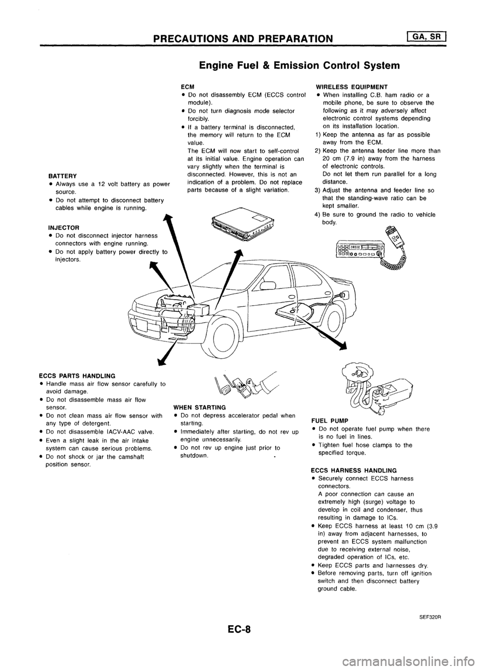
BATTERY • Always usea12 volt battery aspower
source.
• Do not attempt todisconnect battery
cables whileengine isrunning.
INJECTOR • Do not disconnect injectorharness
connectors withengine running.
• Do not apply battery powerdirectly to
injectors.
ECCS PARTS HANDLING
• Handle massairflow sensor carefully to
avoid damage.
• Do not disassemble massairflow
sensor.
• Do not clean massairflow sensor with
any type ofdetergent.
• Do not disassemble IACV-AACvalve.
• Even aslight leakinthe airintake
system cancause serious problems.
• Do not shock orjar the camshaft
position sensor. ECM
• Do not disassembly EGM(EGGS control
module).
• Do not turn diagnosis modeselector
forcibly.
• Ifabattery terminal isdisconnected,
the memory willreturn tothe ECM
value.
The ECM willnow start toself-control
at its initial value. Engine operation can
vary slightly whentheterminal is
disconnected. However,thisisnot an
indication ofaproblem. Donot replace
parts because ofaslight variation.
WHEN STARTING
• Do not depress accelerator pedalwhen
starting.
• Immediately afterstarting, donot revup
engine unnecessarily .
• Do not revupengine justprior to
shutdown.
EC-8 WIRELESS
EQUIPMENT
• When installing C.B.hamradio ora
mobile phone, besure toobserve the
following asitmay adversely affect
electronic controlsystems depending
on itsinstallation location.
1) Keep theantenna asfar aspossible
away fromtheEGM.
2) Keep theantenna feederlinemore than
20 em (7.9 in)away fromtheharness
of electronic controls.
Do not letthem runparallel foralong
distance.
3) Adjust theantenna andfeeder lineso
that thestanding-wave ratiocanbe
kept smaller.
4) Be sure toground theradio tovehicle
body.
FUEL PUMP
• Do not operate fuelpump whenthere
is no fuel inlines.
• Tighten fuelhose clamps tothe
specified torque.
ECCS HARNESS HANDLING
• Securely connectEGGSharness
connectors.
A poor connection cancause an
extremely high(surge) voltage to
develop incoil and condenser, thus
resulting indamage toICs .
• Keep ECGS harness atleast 10em (3.9
in) away fromadjacent harnesses, to
prevent anEGGS system malfunction
due toreceiving externalnoise,
degraded operation ofIGs, etc.
• Keep EGCS partsandharnesses dry.
• Before removing parts,turnoffignition
switch andthen disconnect battery
ground cable.
SEF320R