Page 1570 of 1701
ADJUSTMENT
I
RS5F30A
&
RS5F31 A
I
SMT646-A
I"
KV38106000
SMT454-ADifferential
SideBearing Preload
If any ofthe following partsarereplaced, adjustdifferential side
bearing preload.
• Differential case
• Differential sidebearing
• Clutch housing
• Transmission case
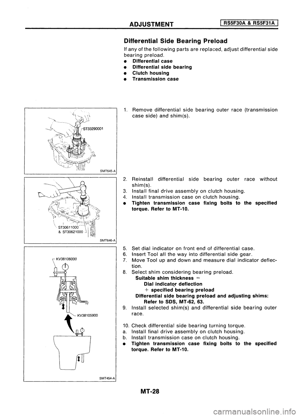
1. Remove differential sidebearing outerrace(transmission
case side) andshim(s).
2. Reinstall differential sidebearing outerracewithout
shim(s).
3. Install finaldrive assembly onclutch housing.
4. Install transmission caseonclutch housing.
• Tighten transmission casefixing boltstothe specified
torque. RefertoMT-10.
5. Set dial indicator onfront endofdifferential case.
6. Insert Toolallthe way intodifferential sidegear.
7. Move Toolupand down andmeasure dialindicator deflec-
tion.
8. Select shimconsidering bearingpreload.
Suitable shimthickness =
Dial
indicat~r
deflection
+ specified bearingpreload
Differential sidebearing preload andadjusting shims:
Refer to50S, MT-62, 63.
9. Install selected shim(s)anddifferential sidebearing outer
race.
10. Check differential sidebearing turningtorque.
a. Install finaldrive assembly onclutch housing.
b. Install transmission caseonclutch housing.
• Tighten transmission casefixing boltstothe specified
torque. RefertoMT-10.
MT-28
Page 1571 of 1701
~casecover"U--0-ring
~spacer
Mainshaft rearbearing ~ Mainshaft
outer race ~
0
bearing
- \ adjusting
shim
I ~--
SMT613AA
SMT599 ADJUSTMENT
I
RS5F30A
&
RS5F31A
I
Differential SideBearing Preload(Cont'd)
c. Measure turningtorqueoffinal drive assembly.
Turning torqueoffinal drive assembly
(New bearing):
Refer toSOS, MT-62.
• When oldbearing isused again, turning torquewillbe
slightly lessthan theabove.
• Make suretorque isclose tothe specified range.
• Changes inturning torqueoffinal drive assembly perrev-
olution shouldbewithin 1.0N'm (10kg-em, 8.7in-Ib) with-
out binding.
Mainshaft BearingPreload
If any ofthe following partsarereplaced, adjustmainshaft bear-
il}g preload.
• Mainshaft
• Mainshaft bearings
• Clutch housing
• Transmission case
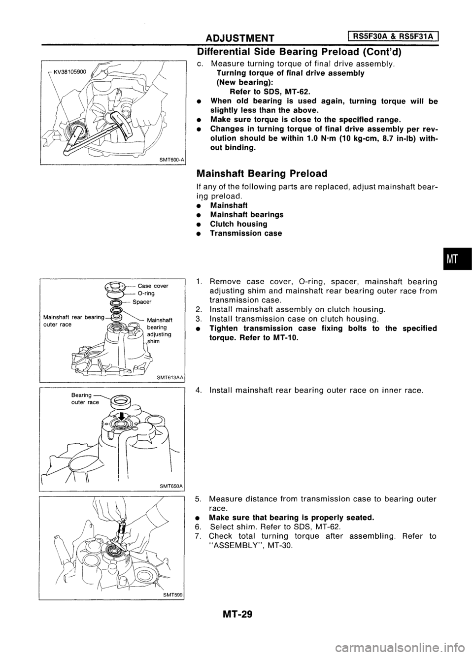
1. Remove casecover, O-ring, spacer, mainshaft bearing
adjusting shimandmainshaft rearbearing outerracefrom
transmission case.
2. Install mainshaft assemblyonclutch housing.
3. Install transmission caseonclutch housing.
• Tighten transmission casefixing boltstothe specified
torque. RefertoMT-10.
4. Install mainshaft rearbearing outerraceoninner race.
5. Measure distancefromtransmission casetobearing outer
race.
• Make surethatbearing isproperly seated.
6. Select shim.RefertoSDS, MT-62.
7. Check totalturning torqueafterassembling. Referto
"ASSEMBLY", MT-30.
MT-29
•
Page 1572 of 1701
ASSEMBLY
I
RS5F30A &RS5F31 A
I
SMT648AA
1.
Install striking rod,lever andinterlock.
• Tape edges ofstriking rodtoavoid damaging oilseal lip
during installation.
• When taped edges ofstriking rodare past theoilseal,
remove tape.
2. Install reverse checksleeve assembly.
3. Install check balls,reverse checkspring andcheck plug.
4. Check reverse checkturning torque(Atstriking rod).
Reverse checkturning torque(Atstriking rod):
Refer toSOS, MT-61.
• Ifnot within specification, selectanother checkplughaving
a different lengthandreinstall it.
Reverse checkplug:
Refer toSOS, MT-61.
5. Install selected reversecheckplug.
• Apply locking sealanttothread ofplug before installing it.
6. Install check ballplug, shiftcheck balland shift check
spring.
7. Install oilpocket.
SMT580
8.
Install gearcomponents ontoclutch housing.
- RS5F30A-
a. Install finaldrive assembly andreverse idlergear.
MT-30
Page 1574 of 1701
ASSEMBLYI
RSSF30A
&
RSSF31 A
I
SMT720
c.
Install mainshaft assembly.
• Take carenottodamage oilchannel wheninserting main-
shaft intoclutch housing.
9. Apply grease toshifter caps,theninstall itto control
bracket. Installcontrol bracket with1st
&
2nd shift fork.
10. Install 3rd
&
4th and 5thshift forks.
11. Insert forkshaft.
• Apply multi-purpose greasetosupport springbefore install-
ing.
12. Install reverse idlerspacer.
13. Apply recommended sealanttomating surface ofclutch
housing.
14. Install transmission caseonclutch housing.
15. Measure totalturning torque.
Total (Final drive+Mainshaft) turningtorque(New
bearing): Refer toSOS, MT-62.
• When oldbearing isused again, turning torquewillbe
slightly lessthan theabove.
• Make suretorque isclose tothe specified range.
MT-32
Page 1596 of 1701
ADJUSTMENT
I
RS5F32A
I
SMT646-A
SMT454-B Differential
SideBearing Preload
If any ofthe following partsarereplaced, adjustdifferential side
bearing preload.
• Differential case
• Differential sidebearing
• Clutch housing
• Transmission case
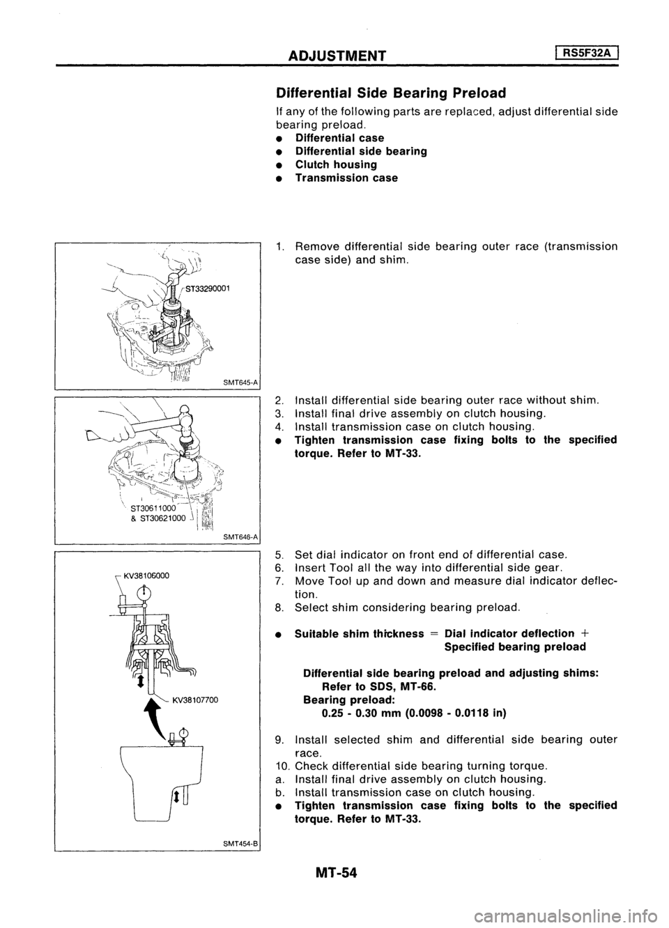
1. Remove differential sidebearing outerrace(transmission
case side) andshim.
2. Install differential sidebearing outerracewithout shim.
3. Install finaldrive assembly onclutch housing.
4. Install transmission caseonclutch housing.
• Tighten transmission casefixing boltstothe specified
torque. RefertoMT -33.
5. Set dial indicator onfront endofdifferential case.
6. Insert Toolallthe way intodifferential sidegear.
7. Move Toolupand down andmeasure dialindicator deflec-
tion.
8. Select shimconsidering bearingpreload.
• Suitable shimthickness
=
Dial indicator deflection +
Specified bearingpreload
Differential sidebearing preload andadjusting shims:
Refer toSDS, MT-66.
Bearing preload:
0.25 -0.30 mm(0.0098 -0.0118 in)
9. Install selected shimanddifferential sidebearing outer
race.
10. Check differential sidebearing turningtorque.
a. Install finaldrive assembly onclutch housing.
b. Install transmission caseonclutch housing.
• Tighten transmission casefixing boltstothe specified
torque. RefertoMT-33.
MT-54
Page 1597 of 1701
ADJUSTMENT
I
RS5F32A
I
Differential SideBearing Preload(Cont'd)
c. Measure turningtorqueoffinal drive assembly.
Turning torqueoffinal drive assembly
(New bearing):
2.9 -6.9 N'm (30-70 kg-em, 26-61 in-Ib)
• When oldbearing isused again, turning torquewillbe
slightly lessthan theabove.
• Make suretorque isclose tothe specified range.
• Changes inturning torqueoffinal drive assembly perrev-
olution shouldbewithin 1.0N'm (10kg-em, 8.7in-Ib) with-
out binding.
MT-55
•
Page 1598 of 1701
ASSEMBLY
I
RS5F32A ,
J
Reverse checkplug
~ Reverse checkspring
V
Check ball(Large)
"-- Check ball(Small)
b~6
,
~
l ~---- -'.
SMT584
SMT688
SMT648AA SMT671B
1.
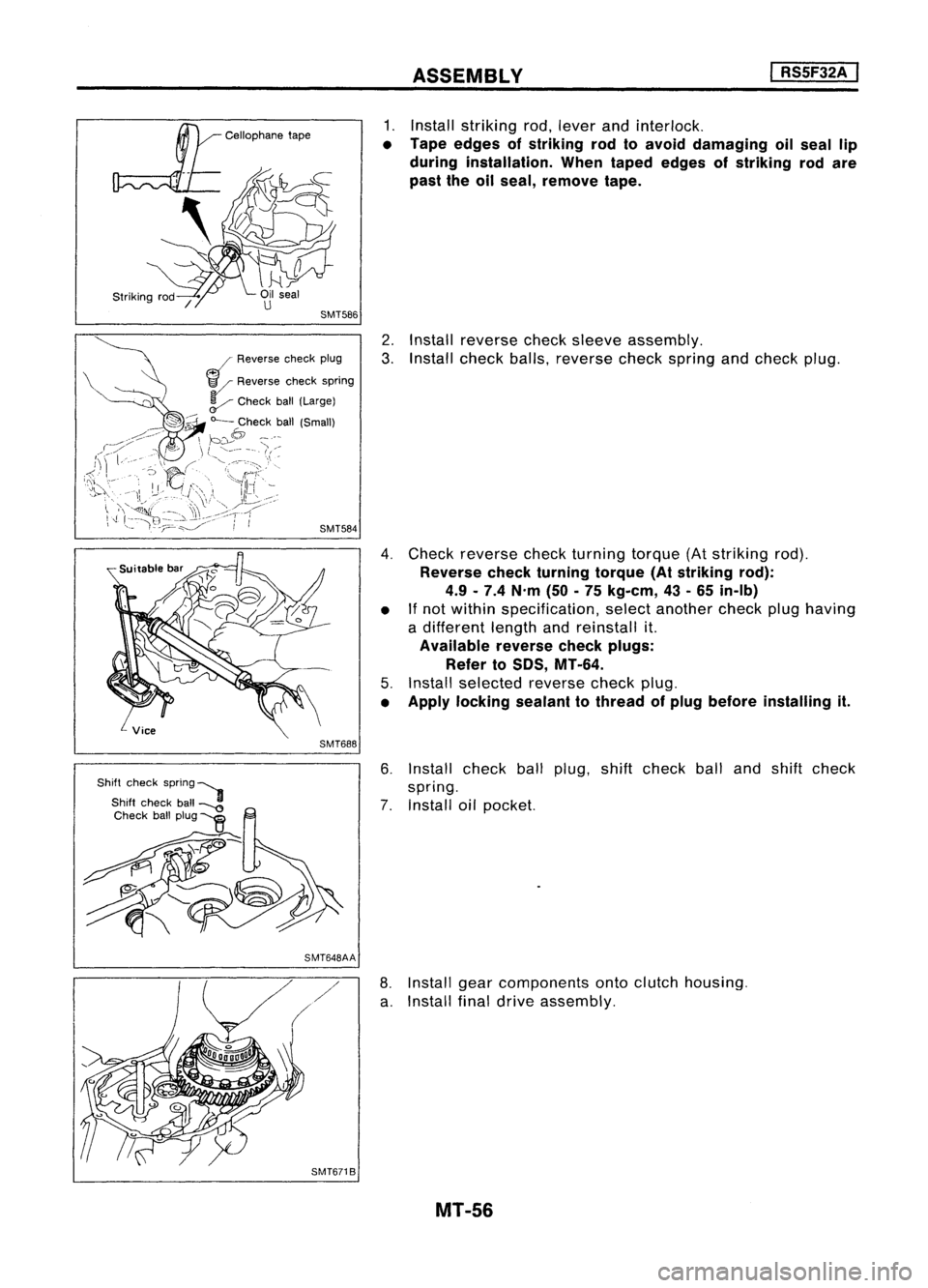
Install striking rod,lever andinterlock.
• Tape edges ofstriking rodtoavoid damaging oilseal lip
during installation. Whentaped edges ofstriking rodare
past theoilseal, remove tape.
2. Install reverse checksleeve assembly.
3. Install check balls,reverse checkspring andcheck plug.
4. Check reverse checkturning torque(Atstriking rod).
Reverse checkturning torque(Atstriking rod):
4.9 -7.4 N'm (50-75 kg-em, 43-65 in-Ib)
• If
not within specification, selectanother checkplughaving
a different lengthandreinstall it.
Available reversecheckplugs:
Refer to
50S,
MT-64.
5. Install selected reversecheckplug.
• Apply locking sealanttothread ofplug before installing it.
6. Install checkballplug, shiftcheck ballandshift check
spring.
7. Install oilpocket.
8. Install gearcomponents ontoclutch housing.
a. Install finaldrive assembly.
MT-56
Page 1603 of 1701
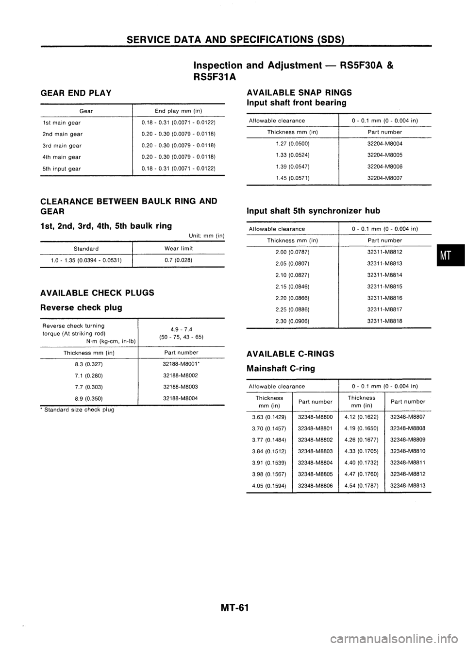
SERVICEDATAANDSPECIFICATIONS (SOS)
Inspection andAdjustment -RS5F30A
&
RS5F31A
GEAR ENDPLAY
Gear
1st main gear
2nd main gear
3rd main gear
4th main gear
5th input gear End
play mm(in)
0,18 -0,31 (0,0071 -0,0122)
0,20 -0,30 (0,0079 -0,0118)
0,20 -0,30 (0,0079 -0,0118)
0,20 -0,30 (0,0079 -0,0118)
0,18 -031 (0,0071 -0,0122) AVAILABLE
SNAPRINGS
Input shaftfrontbearing
Allowable clearance
Thickness mm(in)
1,27 (0,0500)
1,33 (0,0524)
1,39 (0,0547)
1.45 (0,0571) 0-
0,1 mm (0-0,004 in)
Part number
32204-M8004
32204-M8005
32204-M8006
32204-M8007
CLEARANCE BETWEENBAULKRINGAND
GEAR
1st, 2nd, 3rd,4th,5thbaulk ring
Standard
1.0 -1.35 (0.0394 -0.0531)
AVAILABLE CHECKPLUGS
Reverse checkplug
Reverse checkturning
torque (Atstriking rod)
N'm (kg-em, in-Ib)
Thickness mm(in)
8.3 (0.327)
7.1 (0.280)
7.7 (0.303)
8.9 (0.350)
, Standard sizecheck plug Unit:
mm(in)
Wear limit
0.7 (0.028)
4.9 -7.4
(50 -75, 43-65)
Part number
32188-M8001' 32188-M8002
32188-M8003
32188-M8004 Input
shaft5thsynchronizer hub
Allowable clearance 0-
0,1 mm (0-0,004 in)
Thickness mm(in) Part
number
2,00 (00787) 32311-M8812
•
2,05
(0,0807) 32311-M8813
2,10 (0,0827) 32311-M8814
2,15 (0,0846) 32311-M8815
2,20 (0.0866) 32311-M8816
2.25 (0.0886) 32311-M8817
2.30 (0.0906) 32311-M8818
AVAILABLE C-RINGS
Mainshaft C-ring
Allowable clearance 0-
01 mm (0-0.004 in)
Thickness Partnumber Thickness
Partnumber
mm (in) mm
(in)
3.63 (01429) 32348-M8800
4.12(0.1622) 32348-M8807
3.70 (0.1457) 32348-M8801 4.19
(0,1650) 32348-M8808
3.77 (0.1484) 32348-M8802 4.26
(0.1677) 32348-M8809
3.84 (0.1512) 32348-M8803 4.33
(0.1705) 32348-M8810
3.91 (0.1539) 32348-M8804
4.40(0.1732) 32348-M8811
3,98 (0.1567) 32348-M8805 4.47
(0.1760) 32348-M8812
4.05 (0.1594) 32348-M8806 4.54
(0.1787) 32348-M8813
MT-61