Page 1604 of 1701

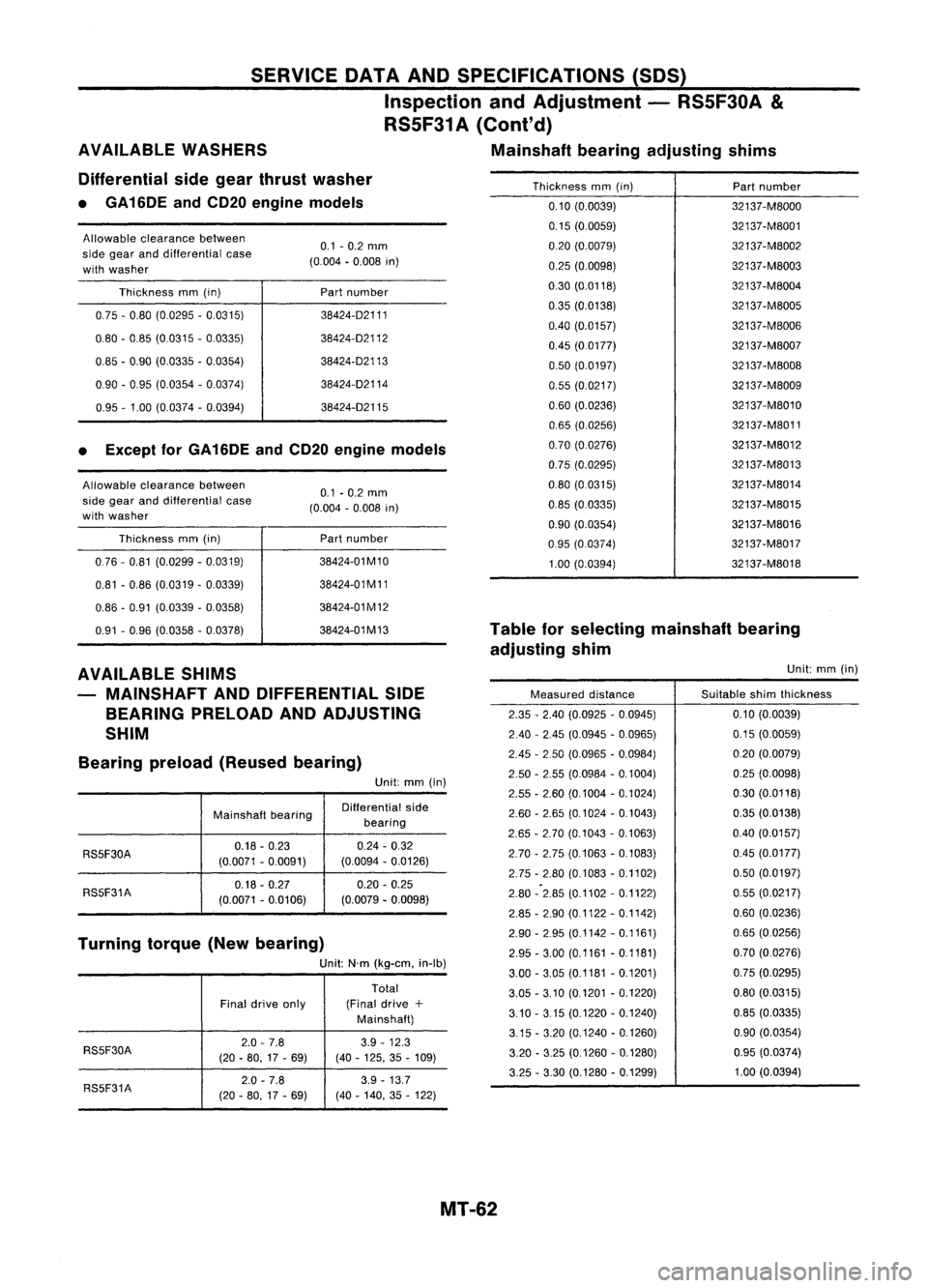
Thicknessmm(in)
Partnumber
0.10 (0.0039) 32137-M8000
0.15 (0.0059) 32137-M8001
0.20 (0.0079) 32137-M8002
0.25 (0.0098) 32137-M8003
0.30 (0.0118) 32137-M8004
035 (0.0138) 32137-M8005
0.40 (0.0157) 32137-M8006
0.45 (00177) 32137-M8007
0.50 (0.0197) 32137-M8008
0.55 (0.0217) 32137-M8009
0.60 (0.0236) 32137-M8010
0.65 (0.0256) 32137-M8011
0.70 (0.0276) 32137
-M8012
0.75 (0.0295) 32137-M8013
080 (0.0315) 32137-M8014
0.85 (0.0335) 32137-M8015
0.90 (0.0354) 32137
-M8016
095 (0.0374) 32137-M8017
1.00 (0.0394) 32137-M8018
Table forselecting mainshaft bearing
adjusting shim
38424-02111
38424-02112
38424-02113
38424-02114
38424-02115
Part
number
Part number
38424-01 M10
38424-01 M11
38424-01 M12
38424-01M13 0.1
-0.2 mm
(0.004 -0.008 in)
0.1 -0.2 mm
(0.004 -0.008 in)
Thickness
mm(in)
0.75 -0.80 (0.0295 -0.0315)
0.80 -0.85 (0.0315 -0.0335)
0.85 -0.90 (0.0335 -0.0354)
0.90 -0.95 (0.0354 -0.0374)
0.95 -1.00 (0.0374 -0.0394)
Thickness mm(in)
076 -0.81 (0.0299 -0.0319)
0.81 -0.86 (0.0319 -0.0339)
0.86 -0.91 (0.0339 -0.0358)
0.91 -0.96 (0.0358 -0.0378)
Allowable
clearance between
side gear anddifferential case
with washer
Allowable
clearance between
side gear anddifferential case
with washer
• Except forGA16DE andCD20 engine models
SERVICE
DATAANDSPECIFICATIONS (SDS)
Inspection andAdjustment -RS5F30A
&
RS5F31 A(Cont'd)
AVAILABLE WASHERS Mainshaftbearingadjusting shims
Differential sidegear thrust washer
• GA16DE andCD20 engine models
AVAILABLE SHIMS
MAINSHAFT ANDDIFFERENTIAL SIDE
BEARING PRELOAD ANDADJUSTING
SHIM
Bearing preload(Reused bearing)
Unit:mm(in)
Mainshafl bearing Oifferential
side
bearing
RS5F30A 0.18
-0.23 0.24-0.32
(0.0071 -0.0091) (0.0094
-0.0126)
RS5F31A 0.18
-0.27 0.20
-0.25
(0.0071 -0.0106) (0.0079
-0.0098)
Turning torque(Newbearing)
Unit:N'm(kg-em, in-Ib)
Total
Final drive only (Final
drive+
Mainshafl)
RS5F30A 2.0
-7.8 3.9-12.3
(20 -80, 17-69) (40
-125, 35-109)
2.0 -7.8 3.9
-13.7
RS5F31A (20-80, 17-69) (40-140, 35-122) Measured
distance
2.35 -2.40 (0.0925 -0.0945)
2.40 -2.45 (0.0945 -0.0965)
2.45 -2.50 (0.0965 -0.0984)
2.50 -2.55 (0.0984 -0.1004)
2.55 -2.60 (0.1004 -0.1024)
2.60 -2.65 (0.1024 -0.1043)
2.65 -2.70 (0.1043 -0.1063)
2.70 -2.75 (0.1063 -0.1083)
2.75 -2.80 (0.1083 -0.1102)
2.80 -2.85 (0.1102 -0.1122)
2.85 -2.90 (0.1122 -0.1142)
2.90 -2.95 (0.1142 -0.1161)
2.95 -3.00 (0.1161 -0.1181)
3.00 -3.05 (0.1181 -0.1201)
3.05 -3.10 (0.1201 -0.1220)
3.10 -315 (0.1220 -0.1240)
3.15 -3.20 (0.1240 -0.1260)
3.20 -3.25 (0.1260 -0.1280)
3.25 -3.30 (0.1280 -0.1299) Unit:
mm(in)
Suitable shimthickness
0.10 (0.0039)
0.15 (0.0059)
0.20 (0.0079)
0.25 (0.0098)
0.30 (0.0118)
0.35 (0.0138)
0.40 (0.0157)
0.45 (0.0177)
0.50 (0.0197)
0.55 (0.0217)
0.60 (0.0236)
0.65 (0.0256)
0.70 (0.0276)
0.75 (0.0295)
0.80 (0.0315)
0.85 (0.0335)
0.90 (0.0354)
0.95 (0.0374)
1.00 (0.0394)
MT-62
Page 1606 of 1701

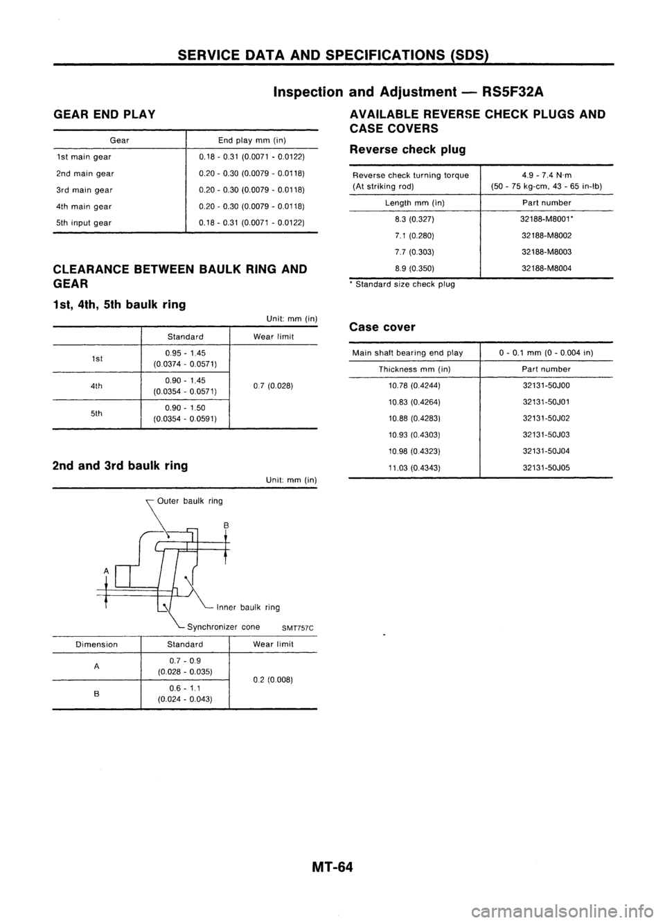
GEARENDPLAY SERVICE
DATAANDSPECIFICATIONS (SOS)
Inspection andAdjustment -RS5F32A
AVAILABLE REVERSECHECKPLUGSAND
CASE COVERS
CLEARANCE BETWEENBAULKRINGAND
GEAR
1 st, 4th, 5thbaulk ring
Gear
1st main gear
2nd main gear
3rd main gear
4th main gear
5th input gear End
play mm(in)
0.18 -0.31 (0.0071 -0.0122)
0.20 -0.30 (0.0079 -0.0118)
0.20 -0.30 (0.0079 -0.0118)
0.20 -0.30 (0.0079 -0.0118)
0.18 -0.31 (0.0071 -0.0122) Reverse
checkplug
Reverse checkturning torque
(At striking rod)
Length mm(in)
8.3 (0.327)
7.1 (0.280)
7.7 (0.303)
8.9 (0.350)
* Standard sizecheck plug 4.9
-7.4 N'm
(50 -75 kg-em, 43-65 in-Ib)
Part number
32188-M8001*
32188-M8002
32188-M8003
32188-M8004
Unit: mm(in)
Standard Wear
limit
1st 0.95
-1.45
(0.0374 -0.0571)
4th 0.90
-1.45
07(0.028)
(0.0354 -0.0571)
5th 0.90
-1.50
(0.0354 -0.0591)
2nd and 3rdbaulk ring
Unit:mm(in)
:I{ ~
'00"
',,'k
,iog
\..- Synchronizer coneSMT757C
Dimension StandardWear
limit
A 0.7
-0.9
(0.028 -0.035)
02(0008)
B
0.6
-1.1
(0.024 -0.043) Case
cover
Main shalt bearing endplay
Thickness mm(in)
10.78 (0.4244)
10.83 (0.4264)
10.88 (0.4283)
10.93 (0.4303)
10.98 (0.4323)
11.03 (0.4343) 0-
0.1 mm (0-0.004 in)
Part number
32131-50JOO
32131-50J01
32131-50J02
32131-50J03
32131-50J04
32131-50J05
MT-64
Page 1608 of 1701
Unit:mm(in)
2.9 -6.9 (30-70, 26-61)
0.25
-0.30 (0.0098 -0.0118)
Differential
sidebearing
Final drive
Bearing
preload(Reused bearing)
Turning torque(Newbearing)
Unit:N'm(kg-cm, in-Ib)
Reverse brakecam
H SERVICE
DATAANDSPECIFICATIONS (SDS)
Inspection andAdjustment -RS5F32A (Cont'd)
INPUT SHAFT BRAKING MECHANISM AVAILABLESHIMS
DIFFERENTIAL SIDEBEARING
PRELOAD ANDADJUSTING SHIM
Reverse
brakeearn
SMT735B
Maximum height"H"between
the control bracket fittingsur-
face and1-2shiller 67.16
-67.64
(2.6441 -2.6330) Differential
sidebearing adjusting shims
mm (in)
Clearance "C"between
reverse brakecarnandstriking
lever c
SMT736B
0.05 -0.125
(0.0020 -0.0049) Thickness
mm(in)
Partnumber
0.44 (0.0173)
38454-M8000
0.48 (0.0189)
38454-M8001
0.56 (0.0220) 38454-M8003
0.60 (0.0236) 38454-M8004
0.64 (0.0252) 38454-M8005
0.68 (0.0268) 38454-M8006
0.72 (00283) 38454-M8007
0.76 (00299)
38454-M8008
0.80 (0.0315)
38454-M8009
0.84 (0.0331) 38454-M8010
0.88 (0.0346) 38454-M8011
mrn (in)
MT-66
Page 1610 of 1701
PRECAUTIONSANDPREPARATION
SBR820B Precautions
• When installing eachrubber part,finaltightening mustbe
carried outunder unladen condition* withtires onground.
*:
Fuel, radiator coolantandengine oilfull. Spare tire,jack,
hand tools andmats indesignated positions.
• Use flare nutwrench whenremoving orinstalling brake
tubes.
• After installing removedsuspension parts,check wheel
alignment.
• Donot jack upatthe trailing armandlateral link.
• Always torquebrakelineswhen installing.
Special Service Tools
Tool number
Tool name Description
GG9431 0000
Flare nuttorque
wrench
HT71780000
Spring compressor
ST35652000
Shock absorber
attachment
NT406
NT144
NT145
Removing
andinstalling brakepiping
a:
10
mm
(0.39
in)
Removing andinstalling coilspring
Fixing strutassembly
Tool name
Description
Commercial
ServiceTools
Equivalent to
GG9431 0000
G)
Flare nutcrows
foot
@
Torque wrench Removing
andinstalling brakepiping
NT360
a:
10
mm
(0.39
in)
RA-2
Page 1612 of 1701
SMA525A
SMA113
---I
SRA690A ON-VEHICLE
SERVICE
Rear AxleandRear Suspension Parts
Check axleandsuspension partsforexcessive play,wear or
damage.
• Shake eachrearwheel tocheck forexcessive play.
• Retighten allnuts andbolts tothe specified torque.
Tightening torque:
Refer toREAR SUSPENSION (RA-8).
• Check shockabsorber for
oil
leakage orother damage.
Rear Wheel Bearing
• Check axialendplay.
Axial endplay:
0.05 mm(0.0020 in)orless
• Check thatwheel hubbearings operatesmoothly.
• Check tightening torqueofwheel bearing locknut.
(OJ:
186 •255 N.m (19-26 kg-m, 137•188 ft-Ib)
• Replace wheelbearing assembly ifthere isaxial endplay
or wheel bearing doesnotturn smoothly. RefertoREAR
AXLE -Wheel Hub(RA-6).
RA-4
Page 1614 of 1701
REARAXLE
Wheel Hub
SEC. 430
SRA710A
6
~
186 •255
(19 •26, 137 -188)
Drum
brake
r2'\
Front ~22-29 (2.2 •3.0, 16-22)
Disc
brake
25 -33(2.5 -3.4, 18-25)
~ :N.m (kg-m. ft-Ib)
G)
Spindle
@
Baffle plate
@
Back plate
@
Wheel hubbearing
@
Washer
@
Wheel bearing locknut
(J)
Cotter pin
@
Hubcap
@
ABS sensor
REMOVAL
CAUTION:
• Before removing therear wheel hubassembly, disconnect
the ABS wheel sensor fromtheassembly. Thenmove it
away fromthehub assembly. Failuretodo somay result in
damage tothe sensor wiresandthesensor becoming inop-
erative.
• Wheel hubbearing doesnotrequire maintenance. Ifany of
the following symptoms arenoted, replace wheelhubbear-
ing assembly.
• Growling noiseisemitted fromwheel hubbearing during
operation.
• Wheel hubbearing dragsorturns roughly. Thisoccurs
when turning hubbyhand afterbearing locknutistightened
to specified torque.
RA-6
Page 1617 of 1701

SRA696A
SRA697A
S
Control rod
Lateral link
~H";""I"
ITorsion
beam
SRA698AREAR
SUSPENSION
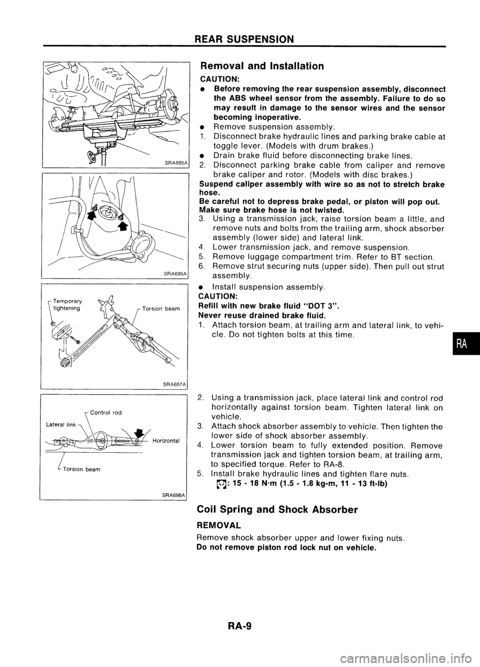
Removal andInstallation
CAUTION:
• Before removing therear suspension assembly,disconnect
the ABS wheel sensor fromtheassembly. Failuretodo so
may result indamage tothe sensor wiresandthesensor
becoming inoperative.
• Remove suspension assembly.
1. Disconnect brakehydraulic linesandparking brakecableat
toggle lever.(Models withdrum brakes.)
• Drain brake fluidbefore disconnecting brakelines.
2. Disconnect parkingbrakecablefromcaliper andremove
brake caliper androtor. (Models withdiscbrakes.)
Suspend caliperassembly withwire soasnot tostretch brake
hose.
Be careful nottodepress brakepedal, orpiston willpop out.
Make surebrake hoseisnot twisted.
3. Using atransmission jack,raise torsion beamalittle, and
remove nutsandbolts fromthetrailing arm,shock absorber
assembly (lowerside)andlateral link.
4. Lower transmission jack,andremove suspension.
5. Remove luggagecompartment trim.Refer toBT section.
6. Remove strutsecuring nuts(upper side).Thenpulloutstrut
assembly.
• Install suspension assembly.
CAUTION: Refill withnewbrake fluid"DOT
3".
Never reusedrained brakefluid.
1. Attach torsion beam,attrailing armandlateral link,tovehi-
cle. Donot tighten boltsatthis time.
2. Using atransmission jack,place lateral linkand control rod
horizontally againsttorsionbeam.Tighten laterallinkon
vehicle.
3. Attach shockabsorber assembly tovehicle. Thentighten the
lower sideofshock absorber assembly.
4. Lower torsion beamtofully extended position.Remove
transmission jackandtighten torsion beam,attrailing arm,
to specified torque.RefertoRA-8.
5. Install brakehydraulic linesandtighten flarenuts.
~: 15-18 N'm (1.5.1.8 kg-m,11-13 ft-Ib)
Coil Spring andShock Absorber
REMOVAL
Remove shockabsorber upperandlower fixing nuts.
Do not remove pistonrodlock nutonvehicle.
RA-9
•
Page 1619 of 1701

REARSUSPENSION
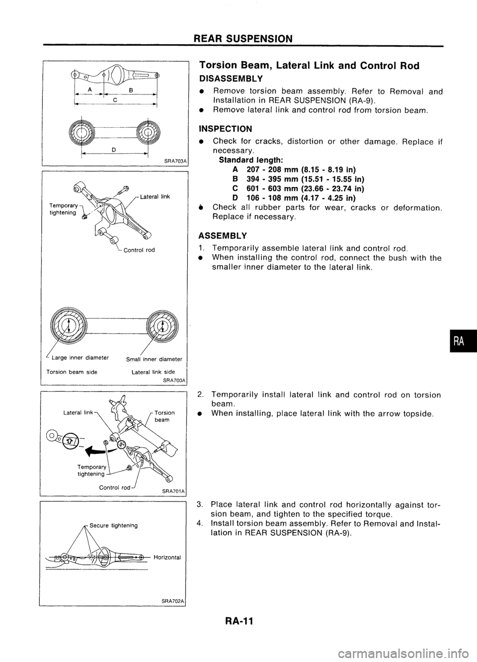
Torsion Beam,Lateral LinkandControl Rod
DISASSEMBL Y
• Remove torsionbeamassembly. RefertoRemoval and
Installation inREAR SUSPENSION (RA-9).
• Remove laterallinkand control rodfrom torsion beam.
Lateral link
SRA703A
INSPECTION
• Check forcracks, distortion orother damage. Replaceif
necessary.
Standard length:
A 207.208 mm(8.15 -8.19 in)
B 394 -395 mm (15.51 -15.55 in)
C 601 -603 mm (23.66 .23.74 in)
o 106 -108 mm (4.17 -4.25 in)
• Check allrubber partsforwear, cracks ordeformation.
Replace ifnecessary.
ASSEMBLY
1. Temporarily assemblelaterallinkand control rod.
• When installing thecontrol rod,connect thebush withthe
smaller innerdiameter tothe lateral link.
Temporary
I~~
Ilgh"oIog ,,'
d) ,
~ Cootrol100
Large innerdiameter
Smallinnerdiameter
•
Torsion beamside Laterallinkside
SRA700A
2.Temporarily installlateral linkand control rodontorsion
beam.
• When installing, placelateral linkwith thearrow topside.
0""
;;~h"0109
~ .$
Horizontal 3.
Place lateral linkand control rodhorizontally againsttor-
sion beam, andtighten tothe specified torque.
4. Install torsion beamassembly. RefertoRemoval andInstal-
lation inREAR SUSPENSION (RA-9).
SRA702A
RA-11