Page 1620 of 1701
SERVICEDATAANDSPECIFICATIONS (50S)
General Specifications
Suspension type
Shock absorber type
Stabilizer Multi-link
beamsuspension
Double-acting hydraulic
Standard equipment
WHEEL ALIGNMENT (Unladen*) Inspection
andAdjustment
WHEEL BEARING
Camber Minimum-1'45'
(-1.75')
Degree minute Nominal
-1'00'
(-1.00')
(Decimal degree) Maximum -0'15'
(-0.25')
Total toe-in Minimum-3
(-0.12)
Distance (A-B) Nominal
1
(0.04)
mm (in) Maximum 5(0.20)
Angle (leftpius right) Minimum -16'(-0.27')
Degree minute Nominal
5'
(0.08')
(Decimal degree)Maximum 26'
(0.43') Wheel
bearing axialendplay
mm (in)
Wheel bearing locknuttighten-
ing torque
N'm(kg-m. ft-lb) 0.05
(0.0020) orless
186 -255
(19 -26, 137 -188)
': Fuel, radiator coolantandengine oilfull. Spare tire.jack, hand
tools andmats indesignated positions.
RA-12
Page 1669 of 1701
Toolnumber
Tool name PRECAUTIONS
ANDPREPARATION
Special Service Tools
Description
KV481 00700
Torque adapter
KV481 02500
Pressure gaugeadapter NT169
NT542 PF3/B"~
@
@
PF3/B"~ ~x1.5 pitch
M16 x1.5 pitch Measuring
pinionrotating torque
Measuring oilpressure
ST27180001
Steering wheelpuller
NT544(1.14
in)
@Q'O
,'25 0;'0'
@ @
MB
x1.25 pitch Removing
andinstalling steeringwheel
HT72520000
Ball joint remover
ST27091000 Pressure gauge
KV481 04400
Rack sealringreformer
ST3127S000
G)
GG91030000
Torque wrench
@ HT62940000
Socket adapter
@
HT62900000
Socket adapter NT546
NT547
NT550
NT541 To
control valve
Shut-off valve
~ 1/4"~rque wrench
~ withrange of
1/4"
to
3/B" 2.9
N.m
~ ""(30kg-em,
'V
'td"
3/B
to
1/2
26
in-Ib)
ST-3 Removing
balljoint
a:
33
mm
(1.30
in)
b: 50
mm
(1.97
in)
r:
R11.5
mm
(0.453
in)
Measuring oilpressure
Reforming teflonring
a: 50 mm (1.97 in)dia.
b: 36 mm (1.42 in)dia.
c:
100
mm
(3.94
in)
Measuring turningtorque
•
Page 1680 of 1701
MANUALSTEERING GEARANDLINKAGE (ModelR24N)
Removal andInstallation
SEC. 480
A :
N.m (kg-m, tt-Ib)
(!)
Hole cover
@
Lower joint
@
Manual steering gearassembly
@
Steering gearmounting clamp
tt'J
29•39
(3.0 -4.0,22 -", ~
~
@~ SST056CA
@
Rack mounting insulator
@
Cotter pin
CAUTION:
The rotation ofthe spiral cable(SRS"Airbag" component part)
is limited.
If
the steering gearmust beremoved, setthe front
wheels inthe straight-ahead direction.Donot rotate thesteer-
ing column whilethesteering gearisremoved.
• Detach tie-rodoutersockets fromknuckle armswithTool.
• Initially, tightennutontie-rod outersocket andknuckle arm
to 29 to39 N'm (3to 4kg-m, 22to29 ft-Ib).
• Tighten nutfurther toalign nutgroove withthefirst pinhole
so cotter pincan beinstalled.
CAUTION:
Tightening torquemustnotexceed 49N.m (5kg-m, 36ft-Ib).
ST-14
Page 1682 of 1701
MANUALSTEERING GEARANDLINKAGE (ModelR24N)
Inspection (Cont'd)
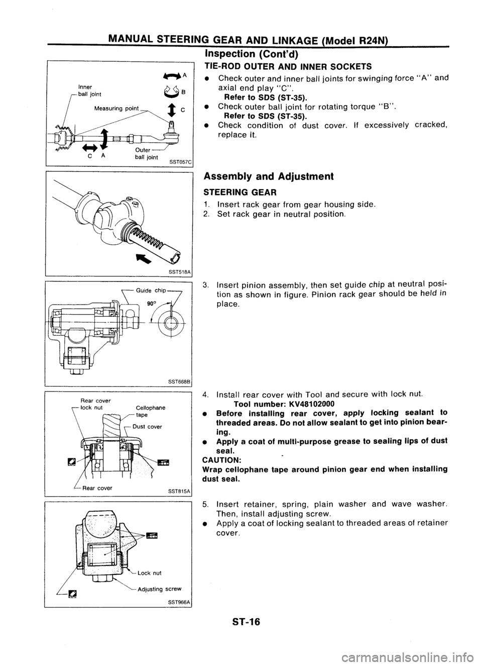
TIE-ROD OUTERANDINNER SOCKETS
...... A •
Check outerandinner balljoints for
swinging
force"A"and
axial endplay "C".
Refer toSOS CST-35).
Measuring point •
Check outerballjoint forrotating torque"B".
Refer toSOS CST-35).
• Check condition ofdust cover. Ifexcessively cracked,
replace it.
SST057C Assembly andAdjustment
STEERING GEAR
1. Insert rackgear from gearhousing side.
2. Set rack gear inneutral position.
SST518A
GO":,%?
'~
SST6688
3.
Insert pinion assembly, thensetguide chipatneutral posi-
tion asshown infigure. Pinionrackgear should be
held
in
place.
SST815A
4.
Install rearcover withTool andsecure withlocknut.
Tool number: KV48102000
• Before installing rearcover, applylocking sealant to
threaded areas.Donot allow sealant toget into pinion bear-
ing.
• Apply acoat ofmulti-purpose greasetosealing lipsofdust
seal.
CAUTION:
Wrap cellophane tapearound piniongearendwhen installing
dust seal.
5. Insert retainer, spring,plainwasher andwave washer.
Then, install adjusting screw.
• Apply acoat oflocking sealant tothreaded areasofretainer
cover.
Adjusting screw
SST966A
5T-16
Page 1683 of 1701
SST272A
Pinion
rotating
torque
MANUAL
STEERING GEARANDLINKAGE (ModelR24N)
Assembly andAdjustment (Cant'd)
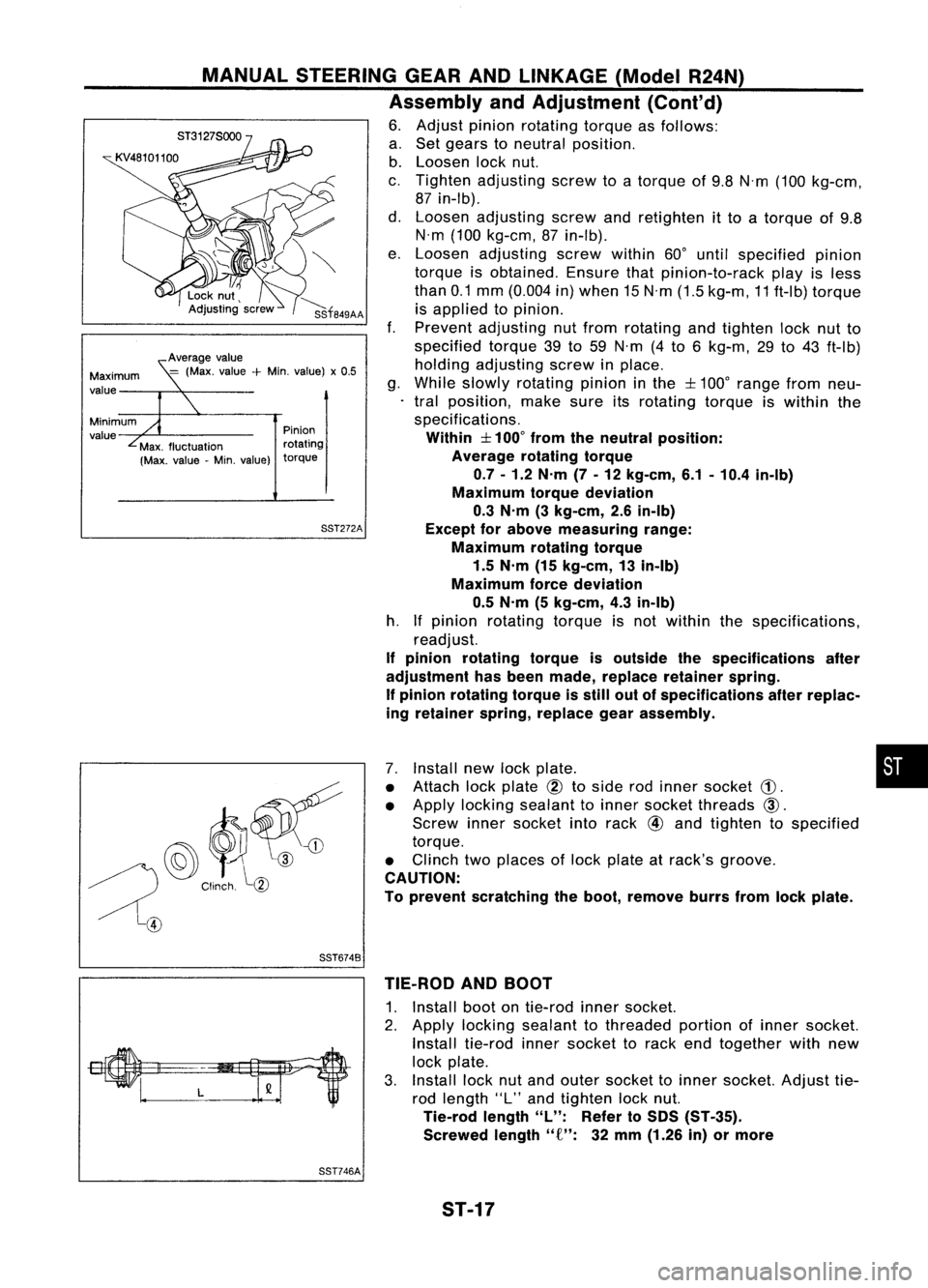
6. Adjust pinionrotating torqueasfollows:
a. Set gears toneutral position.
b. Loosen locknut.
c. Tighten adjusting screwtoatorque of9.8 N'm (100 kg-cm,
87 in-Ib).
d. Loosen adjusting screwandretighten itto atorque of9.8
N'm (100 kg-cm, 87in-Ib).
e. Loosen adjusting screwwithin60°until specified pinion
torque isobtained. Ensurethatpinion-to-rack playisless
than 0.1mm (0.004 in)when 15N'm (1.5kg-m, 11ft-Ib) torque
is applied topinion.
f. Prevent adjusting nutfrom rotating andtighten locknutto
specified torque39to59 N'm (4to 6kg-m, 29to43 ft-Ib)
holding adjusting screwinplace.
g. While slowly rotating pinioninthe
:f::
100° range fromneu-
tral position, makesureitsrotating torqueiswithin the
specifications.
Within
:f::
100° from theneutral position:
Average rotatingtorque
0.7 -1.2 N'm (7-12 kg-em, 6.1-10.4 in-Ib)
Maximum torquedeviation
0.3 N'm (3kg-em, 2.6in-Ib)
Except forabove measuring range:
Maximum rotatingtorque
1.5 N'm (15kg-em, 13in-Ib)
Maximum forcedeviation
0.5 N'm (5kg-em, 4.3in-Ib)
h. Ifpinion rotating torqueisnot within thespecifications,
readjust.
If pinion rotating torqueisoutside thespecifications after
adjustment hasbeen made, replace retainer spring.
If pinion rotating torqueisstill outofspecifications afterreplac-
ing retainer spring,replace gearassembly.
Average
value
=
(Max. value
+
Min. value) x0.5
Minimum
value Maximum
value
@~~
/) Clinch
l(1)
~@
7.
Install newlockplate. •
• Attach lockplate
@
toside rodinner socket
CD.
• Apply locking sealant toinner socket threads
CID.
Screw innersocket intorack
@
and tighten tospecified
torque.
• Clinch twoplaces oflock plate atrack's
groove.
CAUTION:
To prevent scratching theboot, remove burrsfromlockplate.
SST6748 TIE-ROD ANDBOOT
1. Install bootontie-rod innersocket.
2. Apply locking sealant tothreaded portionofinner socket.
Install tie-rod innersocket torack endtogether withnew
lock plate.
3. Install locknutand outer socket toinner socket. Adjusttie-
rod length "L"and tighten locknut.
Tie-rod length
"L":
Referto50S (ST-35).
Screwed length"
f":
32mm (1.26 in)ormore
SST746A
ST-17
Page 1686 of 1701
POWERSTEERING GEARANDLINKAGE (ModelPR24AC)
Removal andInstallation (Cont'd)
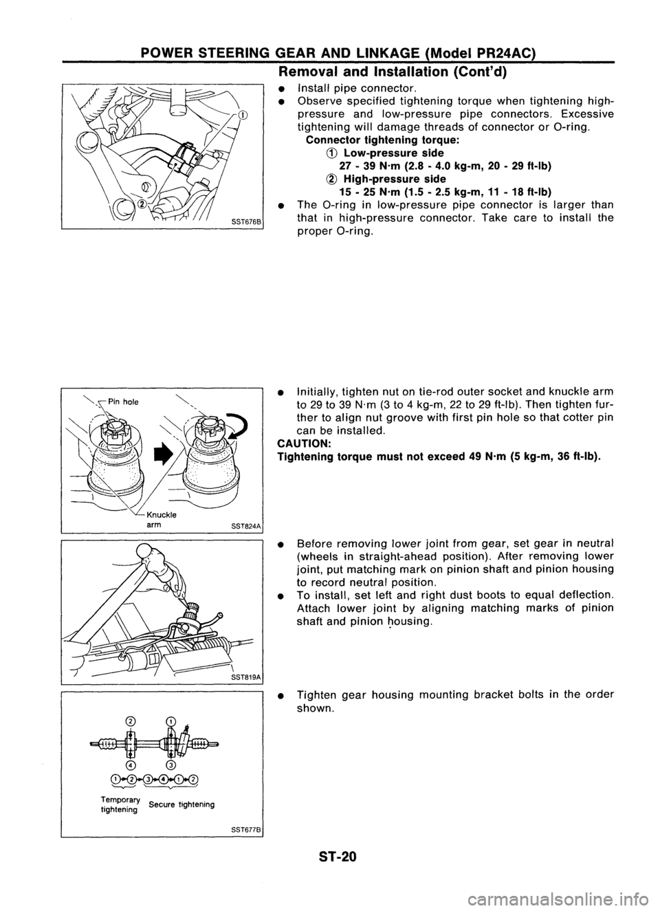
• Install pipeconnector.
• Observe specified tightening torquewhentightening high-
pressure andlow-pressure pipeconnectors. Excessive
tightening willdamage threadsofconnector orO-ring.
Connector tighteningtorque:
CD
Low-pressure side
27 -39 N'm (2.8-4.0 kg-m, 20-29 ft-Ib)
~ High-pressure side
15 -25 N'm (1.5-2.5 kg-m, 11-18 ft-Ib)
• The O-ring inlow-pressure pipeconnector islarger than
that inhigh-pressure connector.Takecaretoinstall the
proper O-ring.
• Initially, tightennutontie-rod outersocket andknuckle arm
to 29 to39 N'm (3to 4kg-m, 22to29 ft-Ib). Thentighten fur-
ther toalign nutgroove withfirstpinhole sothat cotter pin
can beinstalled.
CAUTION:
Tightening torquemustnotexceed 49N'm (5kg-m, 36ft-Ib).
• Before removing lowerjointfrom gear, setgear inneutral
(wheels instraight-ahead position).Afterremoving lower
joint, putmatching markonpinion shaftandpinion housing
to record neutral position.
• Toinstall, setleftand right dustboots toequal deflection.
Attach lowerjointbyaligning matching marksofpinion
shaft andpinion ~ousing.
• Tighten gearhousing mounting bracketboltsinthe order
shown.
o
@
~
'--v---' ~
Temporary ..
tightening SecuretIghtening
SST6778
ST-20
Page 1688 of 1701
POWERSTEERING GEARANDLINKAGE (ModelPR24AC)
Disassembly
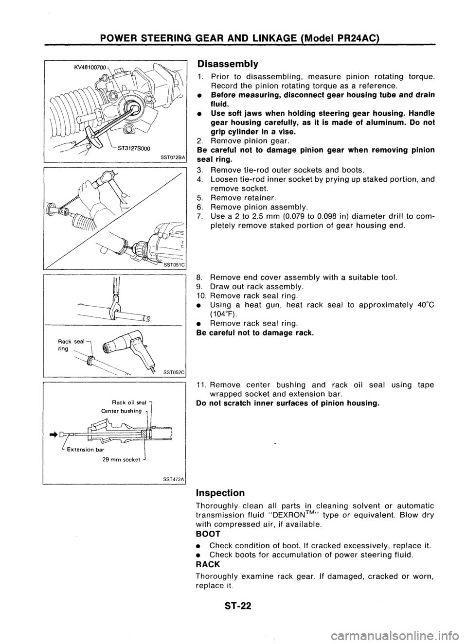
1. Prior todisassembling, measurepinionrotating torque.
Record thepinion rotating torqueasareference.
• Before measuring, disconnectgearhousing tubeanddrain
fluid.
• Use softjaws when holding steering gearhousing. Handle
gear housing carefully, asitis made ofaluminum. Donot
grip cylinder inavise.
2. Remove piniongear.
Be careful nottodamage piniongearwhen removing pinion
seal ring.
3. Remove tie-rodoutersockets andboots.
4. Loosen tie-rodinnersocket byprying upstaked portion, and
remove socket.
5. Remove retainer.
6. Remove pinionassembly.
7. Use a2to 2.5 mm (0.079 to0.098 in)diameter drilltocom-
pletely remove stakedportion ofgear housing end.
8. Remove endcover assembly withasuitable tool.
9. Draw outrack assembly.
10. Remove rackseal ring.
• Using aheat gun,heat racksealtoapproximately 40°C
(104°F).
• Remove racksealring.
Be careful nottodamage rack.
11. Remove centerbushing andrack oilseal using tape
wrapped socketandextension bar.
Do not scratch innersurfaces ofpinion housing .
.. !tension bar
29 mm socket
SST472AInspection
Thoroughly cleanallparts incleaning solventorautomatic
transmission fluid''DEXRON™,, typeorequivalent. Blowdry
with compressed air,ifavailable.
BOOT
• Check condition ofboot. Ifcracked excessively, replaceit.
• Check bootsforaccumulation ofpower steering fluid.
RACK
Thoroughly examinerackgear. Ifdamaged, crackedorworn,
replace it.
ST-22
Page 1689 of 1701
POWERSTEERING GEARANDLINKAGE (ModelPR24AC)
Inspection (Cont'd)
PINION ASSEMBLY
• Thoroughly examinepiniongear.Ifpinion gearisdamaged,
cracked orworn, replace it.
• Check thatallbearings rollfreely. Ensure thatballs, rollers
and races arenotcracked, pittedorworn. Replace ifnec-
essary.
GEAR HOUSING CYLINDER
Check gearhousing cylinder boreforscratches orother dam-
age. Replace ifnecessary.
SST083B
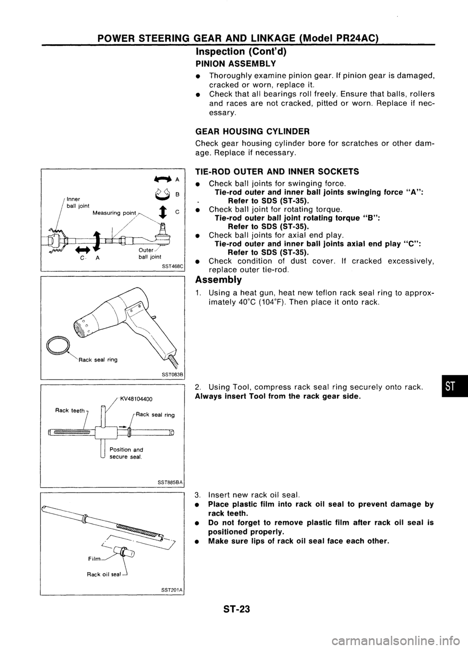
•
2.
Using Tool,compress rackseal ringsecurely ontorack.
Always insertToolfrom therack gear side.
TIE-ROD
OUTERANDINNER SOCKETS
• Check balljoints forswinging force.
Tie-rod outerandinner ball
joints
swinging force
"A":
Refer toSOS (ST-35).
• Check balljoint forrotating torque.
Tie-rod outerballjoint rotating torque
"B":
Refer to50S (ST-35).
• Check balljoints foraxial endplay.
Tie-rod outerandinner balljoints axialendplay
"e":
Refer to50S (ST-35).
• Check condition ofdust cover. Ifcracked excessively,
replace outertie-rod.
Assembly
1. Using aheat gun,heat newteflon rackseal ringtoapprox-
imately 40°C(104°F). Thenplace
it
onto rack.
Us
Rack sealring
Inner
ball joint
+
Measuring pOin;~~
+
C
/'
~R"k ,.. I
""9
Position and
secure seal.
SST885BA
c--.~
~
Film
Rack oilseal 3.
Insert newrack oilseal.
• Place plastic filmintorack oilseal toprevent damage by
rack teeth.
• Donot forget toremove plasticfilmafter rackoilseal is
positioned properly.
• Make surelipsofrack oilseal face each other.
SST201A ST-23