1991 ACURA NSX relay
[x] Cancel search: relayPage 521 of 1640
Anti-lock Brake System (ABS) Description
Features/Construction/Operation (cont'd)
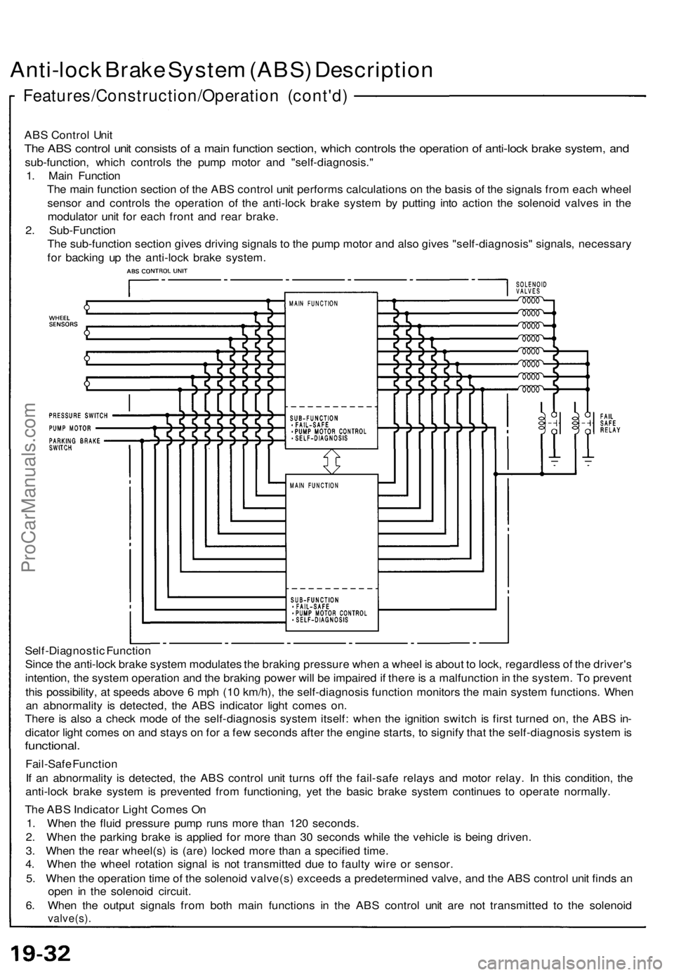
ABS Control Unit
The ABS control unit consists of a main function section, which controls the operation of anti-lock brake system, and
sub-function, which controls the pump motor and "self-diagnosis."
1. Main Function
The main function section of the ABS control unit performs calculations on the basis of the signals from each wheel
sensor and controls the operation of the anti-lock brake system by putting into action the solenoid valves in the
modulator unit for each front and rear brake.
2. Sub-Function
The sub-function section gives driving signals to the pump motor and also gives "self-diagnosis" signals, necessary
for backing up the anti-lock brake system.
Self-Diagnostic Function
Since the anti-lock brake system modulates the braking pressure when a wheel is about to lock, regardless of the driver's
intention, the system operation and the braking power will be impaired if there is a malfunction in the system. To prevent
this possibility, at speeds above 6 mph (10 km/h), the self-diagnosis function monitors the main system functions. When
an abnormality is detected, the ABS indicator light comes on.
There is also a check mode of the self-diagnosis system itself: when the ignition switch is first turned on, the ABS in-
dicator light comes on and stays on for a few seconds after the engine starts, to signify that the self-diagnosis system is
functional.
Fail-Safe Function
If an abnormality is detected, the ABS control unit turns off the fail-safe relays and motor relay. In this condition, the
anti-lock brake system is prevented from functioning, yet the basic brake system continues to operate normally.
The ABS Indicator Light Comes On
1. When the fluid pressure pump runs more than 120 seconds.
2. When the parking brake is applied for more than 30 seconds while the vehicle is being driven.
3. When the rear wheel(s) is (are) locked more than a specified time.
4. When the wheel rotation signal is not transmitted due to faulty wire or sensor.
5. When the operation time of the solenoid valve(s) exceeds a predetermined valve, and the ABS control unit finds an
open in the solenoid circuit.
6. When the output signals from both main functions in the ABS control unit are not transmitted to the solenoid
valve(s).ProCarManuals.com
Page 528 of 1640
ALB Checker
Function Test (cont'd)
4. Turn the Mode Selector switch further to "2". 5. Depress the brake pedal firmly and push the Start
Test switch
The ABS indicator light should not go on while the
Test in Progress light is ON. There should bekickback on the brake pedal. If not as described, go
to troubleshooting, page 19-44 ('91-'92) ('93-'96).
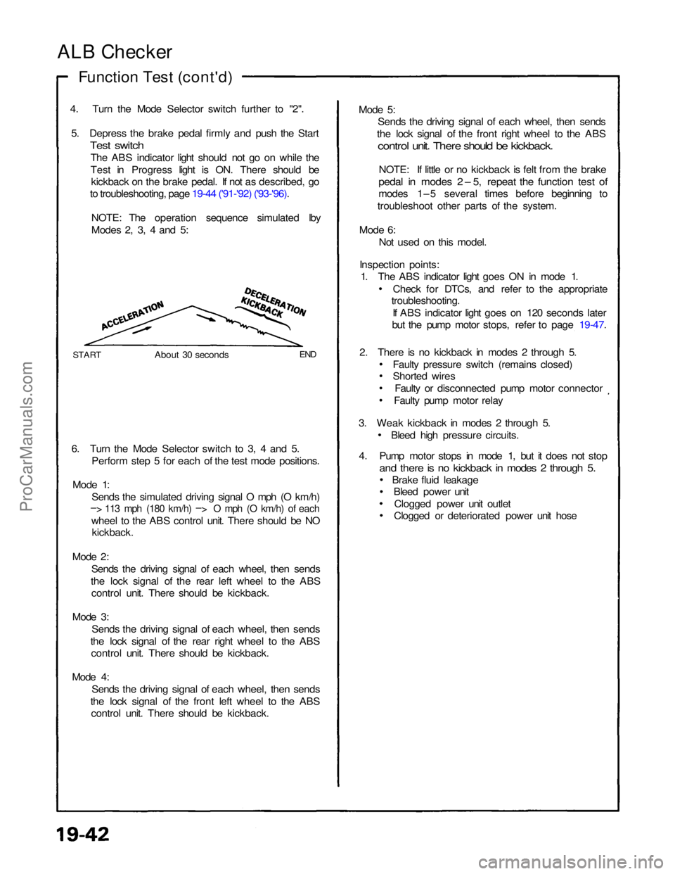
NOTE: The operation sequence simulated lby
Modes 2, 3, 4 and 5:
START
About 30 seconds
END
6. Turn the Mode Selector switch to 3, 4 and 5. Perform step 5 for each of the test mode positions.
Mode 1: Sends the simulated driving signal O mph (O km/h)
– > 113 mph (180 km/h) –
>
O mph (O km/h) of each
wheel to the ABS control unit. There should be NO
kickback.
Mode 2: Sends the driving signal of each wheel, then sends
the lock signal of the rear left wheel to the ABS control unit. There should be kickback.
Mode 3: Sends the driving signal of each wheel, then sends
the lock signal of the rear right wheel to the ABS control unit. There should be kickback.
Mode 4: Sends the driving signal of each wheel, then sends
the lock signal of the front left wheel to the ABS control unit. There should be kickback. Mode 5:
Sends the driving signal of each wheel, then sends
the lock signal of the front right wheel to the ABS
control unit. There should be kickback.
NOTE: If little or no kickback is felt from the brake
pedal in modes 2 – 5, repeat the function test of
modes 1–5 several times before beginning to
troubleshoot other parts of the system.
Mode 6: Not used on this model.
Inspection points: 1. The ABS indicator light goes ON in mode 1.
Check for DTCs, and refer to the appropriate
troubleshooting.
If ABS indicator light goes on 120 seconds later
but the pump motor stops, refer to page 19-47.
2. There is no kickback in modes 2 through 5. Faulty pressure switch (remains closed)
Shorted wiresFaulty or disconnected pump motor connector
Faulty pump motor relay
3. Weak kickback in modes 2 through 5. Bleed high pressure circuits.
4. Pump motor stops in mode 1, but it does not stop
and there is no kickback in modes 2 through 5.
Brake fluid leakageBleed power unit
Clogged power unit outlet
Clogged or deteriorated power unit hoseProCarManuals.com
Page 537 of 1640
Solenoid Flushin g
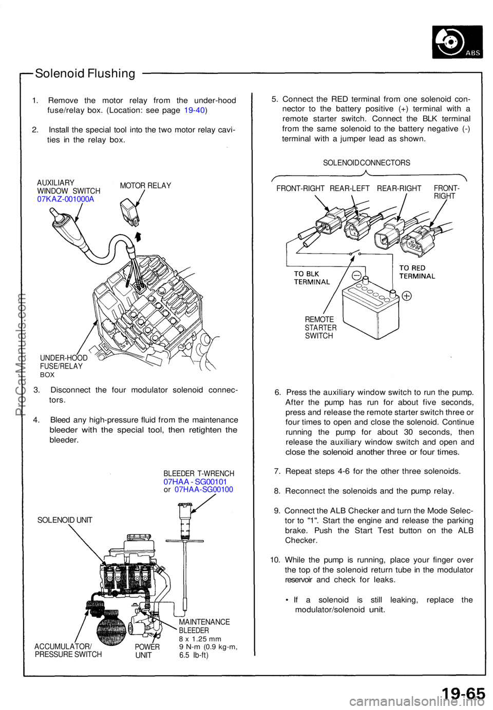
1. Remov e th e moto r rela y fro m th e under-hoo d
fuse/rela y box . (Location : se e pag e 19-40 )
2 . Instal l th e specia l too l int o th e tw o moto r rela y cavi -
tie s i n th e rela y box .
AUXILIAR Y
WINDO W SWITC H
07KAZ-001000 A
MOTOR RELA Y
UNDER-HOO DFUSE/RELAYBOX
3. Disconnec t th e fou r modulato r solenoi d connec -
tors .
4 . Blee d an y high-pressur e flui d fro m th e maintenanc e
bleeder wit h th e specia l tool , the n retighte n th e
bleeder .
SOLENOI D UNI T
BLEEDE R T-WRENC H07HAA - SG0010 1or 07HA A-SG0010 0
ACCUMULATOR /
PRESSUR E SWITC HPOWERUNIT
MAINTENANC EBLEEDER8 x 1.2 5 mm9 N- m (0. 9 kg-m ,6.5 Ib-ft )
5. Connec t th e RE D termina l fro m on e solenoi d con -
necto r t o th e batter y positiv e (+ ) termina l wit h a
remot e starte r switch . Connec t th e BL K termina l
fro m th e sam e solenoi d t o th e batter y negativ e (- )
termina l wit h a jumpe r lea d a s shown .
SOLENOI D CONNECTOR S
FRONT-RIGH T REAR-LEF T REAR-RIGH T
FRONT-RIGHT
REMOT ESTARTE RSWITCH
6. Pres s th e auxiliar y windo w switc h t o ru n th e pump .
Afte r th e pum p ha s ru n fo r abou t fiv e seconds ,
pres s an d releas e th e remot e starte r switc h thre e o r
fou r time s t o ope n an d clos e th e solenoid . Continu e
runnin g th e pum p fo r abou t 3 0 seconds , the n
releas e th e auxiliar y windo w switc h an d ope n an d
clos e th e solenoi d anothe r thre e o r fou r times .
7. Repea t step s 4- 6 fo r th e othe r thre e solenoids .
8 . Reconnec t th e solenoid s an d th e pum p relay .
9 . Connec t th e AL B Checke r an d tur n th e Mod e Selec -
to r t o "1" . Star t th e engin e an d releas e th e parkin g
brake . Pus h th e Star t Tes t butto n o n th e AL B
Checker .
10. Whil e th e pum p i s running , plac e you r finge r ove r
th e to p o f th e solenoi d retur n tub e in th e modulato r
reservoi r an d chec k fo r leaks .
• I f a solenoi d i s stil l leaking , replac e th e
modulator/solenoi d
unit.
ProCarManuals.com
Page 543 of 1640
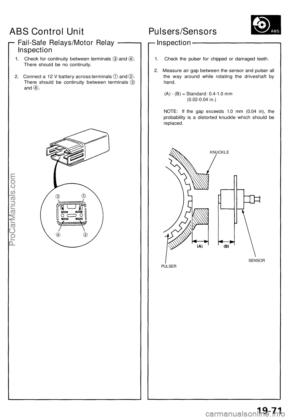
Fail-Safe Relays/Moto r Rela y
Inspectio n
1. Chec k fo r continuit y betwee n terminal s an d
There shoul d b e n o continuity .
2. Connec t a 1 2 V batter y acros s terminal s an d
There shoul d b e continuit y betwee n terminal s
and
Pulsers/Sensor s
Inspection
1. Chec k th e pulse r fo r chippe d o r damage d teeth .
2 . Measur e ai r ga p betwee n th e senso r an d pulse r al l
th e wa y aroun d whil e rotatin g th e driveshaf t b y
hand .
(A) - (B) = Standard: 0.4-1.0 mm
(0.02-0.04 in.)
NOTE: I f th e ga p exceed s 1. 0 m m (0.0 4 in) , th e
probabilit y i s a distorte d knuckl e whic h shoul d b e
replaced .
KNUCKL E
SENSOR
PULSER
ABS Control Unit
ProCarManuals.com
Page 595 of 1640
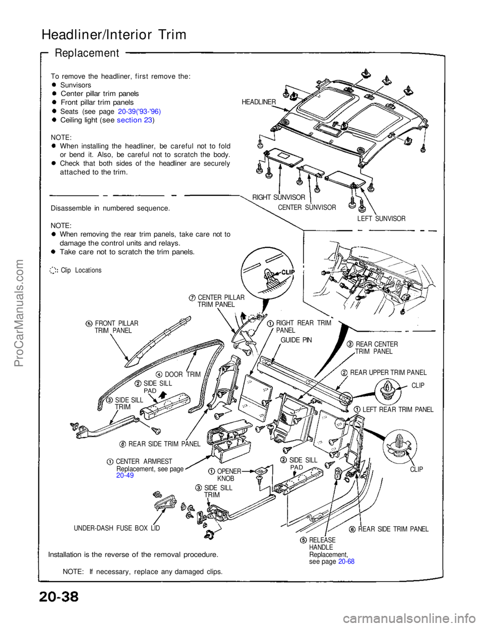
Headliner/lnterior Trim
Replacement
To remove the headliner, first remove the: Sunvisors
Center pillar trim panels
Front pillar trim panels
Seats (see page 20-39('93-'96)
Ceiling light (see section 23)
NOTE:
When installing the headliner, be careful not to fold
or bend it. Also, be careful not to scratch the body.
Check that both sides of the headliner are securely
attached to the trim.
Disassemble in numbered sequence.
NOTE: When removing the rear trim panels, take care not to
damage the control units and relays.
Take care not to scratch the trim panels.
Clip Locations
CENTER PILLAR
TRIM PANEL
FRONT PILLAR
TRIM PANEL
DOOR TRIM
SIDE SILL
PAD
SIDE SILL
TRIM
REAR SIDE TRIM PANEL
CENTER ARMREST
Replacement, see page
20-49
OPENER
KNOB
SIDE SILL
TRIM
UNDER-DASH FUSE BOX LID
Installation is the reverse of the removal procedure.
NOTE: If necessary, replace any damaged clips.
RELEASE
HANDLE
Replacement,
see page 20-68
REAR SIDE TRIM PANEL CLIP
SIDE SILL
PAD
LEFT REAR TRIM PANEL
CLIP
REAR UPPER TRIM PANEL REAR CENTER
TRIM PANEL
GUIDE PIN
RIGHT REAR TRIM
PANEL LEFT SUNVISOR
CENTER SUNVISOR
RIGHT SUNVISOR
HEADLINERProCarManuals.com
Page 684 of 1640
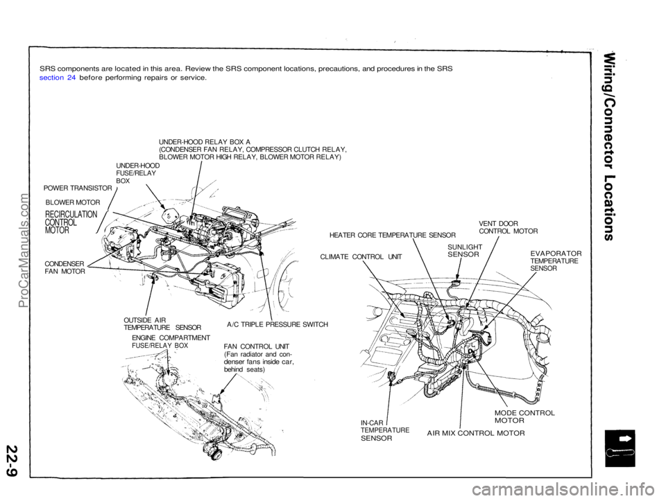
SRS components are located in this area. Review the SRS component locations, precautions, and procedures in the SRS
section 24 before performing repairs or service.
POWER TRANSISTORBLOWER MOTOR
RECIRCULATION
CONTROL
MOTOR
CONDENSER
FAN MOTOR UNDER-HOOD RELAY BOX A
(CONDENSER FAN RELAY, COMPRESSOR CLUTCH RELAY,
BLOWER MOTOR HIGH RELAY, BLOWER MOTOR RELAY)
UNDER-HOOD
FUSE/RELAY
BOX
HEATER CORE TEMPERATURE SENSOR
CLIMATE CONTROL UNIT VENT DOOR
CONTROL MOTOR
OUTSIDE AIR
TEMPERATURE SENSOR ENGINE COMPARTMENT
FUSE/RELAY BOX
A/C TRIPLE PRESSURE SWITCH
FAN CONTROL UNIT (Fan radiator and con-
denser fans inside car,
behind seats)
EVAPORATOR
TEMPERATURE
SENSOR
IN-CAR
TEMPERATURE
SENSOR
MODE CONTROL
MOTOR
AIR MIX CONTROL MOTOR
SUNLIGHT
SENSORProCarManuals.com
Page 703 of 1640
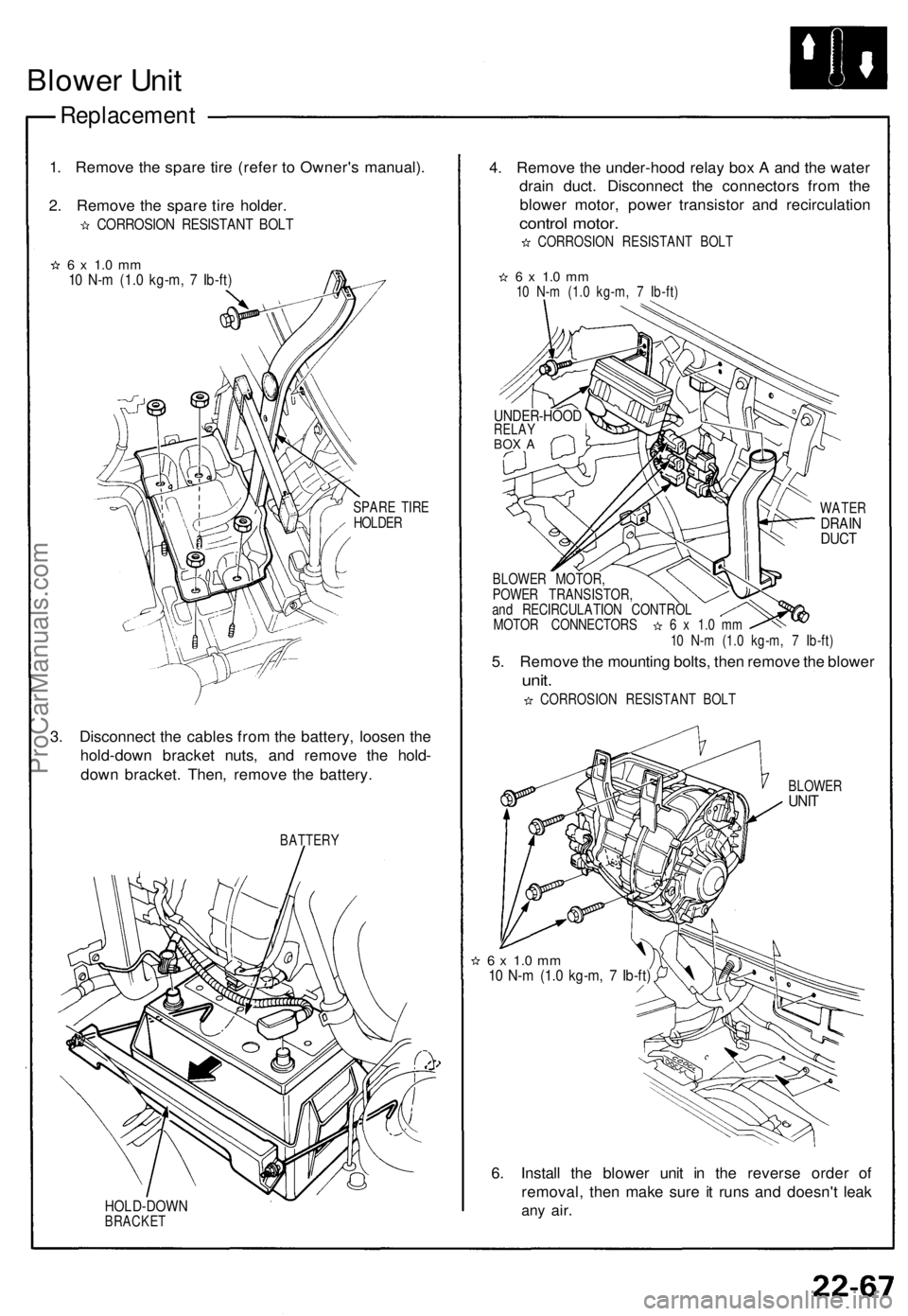
Blower Unit
Replacement
1. Remove the spare tire (refer to Owner's manual).
2. Remove the spare tire holder.
CORROSION RESISTANT BOLT
6 x 1.0 mm
10 N-m (1.0 kg-m, 7 Ib-ft)
SPARE TIRE
HOLDER
3. Disconnect the cables from the battery, loosen the
hold-down bracket nuts, and remove the hold-
down bracket. Then, remove the battery.
BATTERY
HOLD-DOWN
BRACKET
4. Remove the under-hood relay box A and the water
drain duct. Disconnect the connectors from the
blower motor, power transistor and recirculation
control motor.
CORROSION RESISTANT BOLT
6 x 1.0 mm
10 N-m (1.0 kg-m, 7 Ib-ft)
WATER
DRAIN
DUCT
BLOWER MOTOR,
POWER TRANSISTOR,
and RECIRCULATION CONTROL
MOTOR CONNECTORS 6 x 1.0 mm
10 N-m (1.0 kg-m, 7 Ib-ft)
5. Remove the mounting bolts, then remove the blower
unit.
CORROSION RESISTANT BOLT
BLOWER
UNIT
6 x 1.0 mm
10 N-m (1.0 kg-m, 7 Ib-ft)
6. Install the blower unit in the reverse order of
removal, then make sure it runs and doesn't leak
any
air.
UNDER-HOOD
RELAY
BOX AProCarManuals.com
Page 732 of 1640
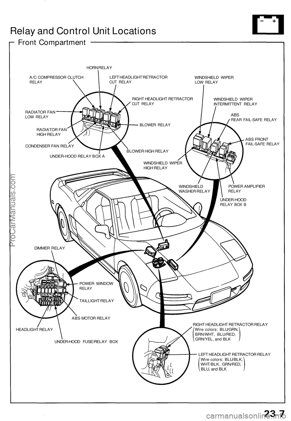
Relay and Control Unit Locations
Front Compartment
HORN RELAY
A/C COMPRESSOR CLUTCH
RELAY
RADIATOR FAN
LOW RELAY
RADIATOR FAN
HIGH RELAY
CONDENSER FAN RELAY
UNDER-HOOD RELAY BOX A
LEFT HEADLIGHT RETRACTOR
CUT RELAY
WINDSHIELD WIPER
LOW RELAY
WINDSHIELD WIPER
INTERMITTENT RELAY
POWER AMPLIFIER
RELAY
ABS
REAR FAIL-SAFE RELAY
ABS FRONT
FAIL-SAFE RELAY
HEADLIGHT RELAY
RIGHT HEADLIGHT RETRACTOR RELAY
Wire colors: BLU/GRN,
BRN/WHT, BLU/RED,
GRN/YEL, and BLK
LEFT HEADLIGHT RETRACTOR RELAY
Wire colors: BLU/BLK,
WHT/BLK, GRN/RED,
BLU,
and BLK
RIGHT HEADLIGHT RETRACTOR
CUT RELAY
BLOWER RELAY
BLOWER HIGH RELAY
WINDSHIELD WIPER
HIGH RELAY
WINDSHIELD
WASHER RELAY
UNDER-HOOD
RELAY BOX B
DIMMER RELAY
POWER WINDOW
RELAY
TAILLIGHT RELAY
ABS MOTOR RELAY
UNDER-HOOD FUSE/RELAY BOXProCarManuals.com