Page 408 of 1640

System Description
Major Components
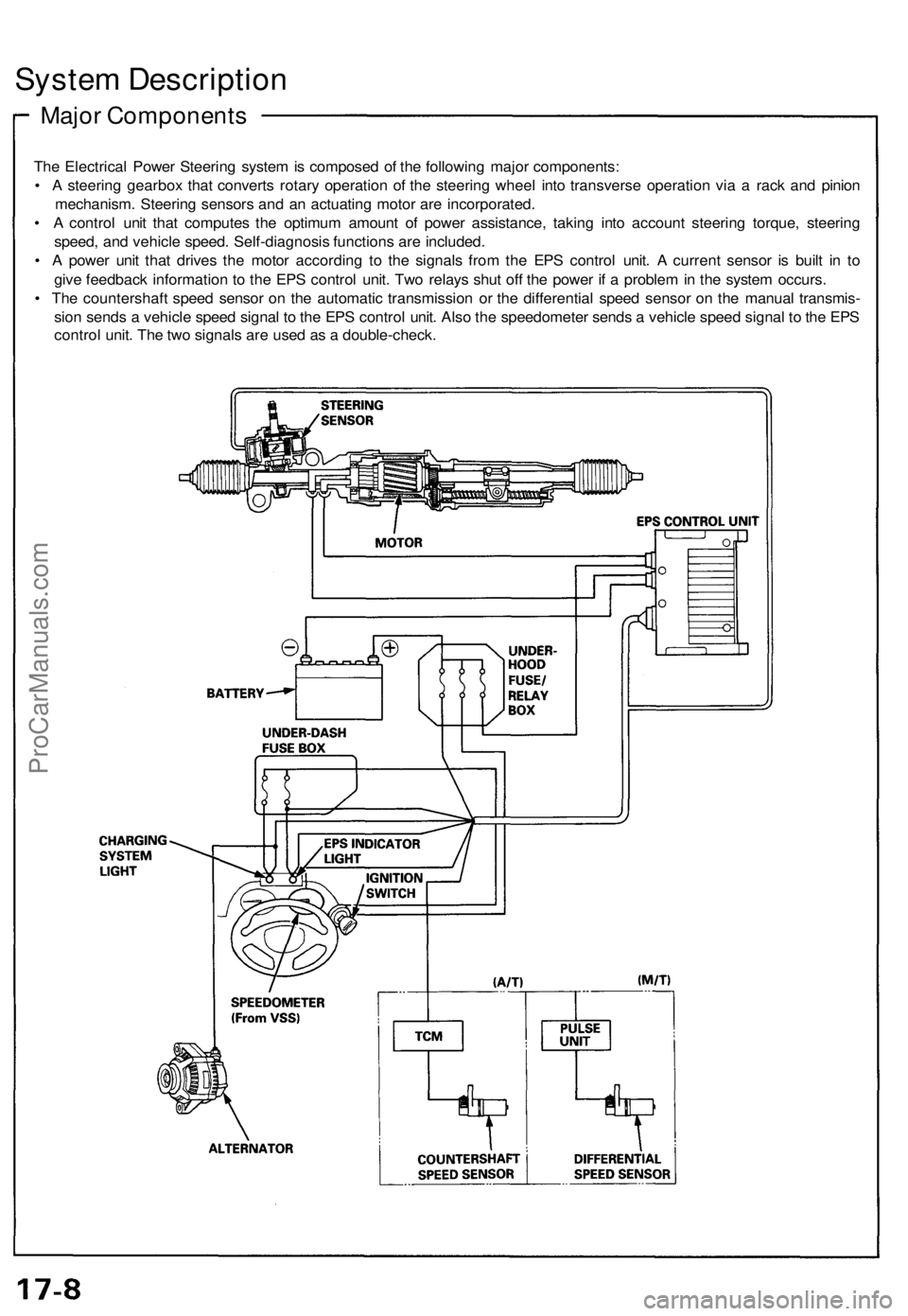
The Electrical Power Steering system is composed of the following major components:
• A steering gearbox that converts rotary operation of the steering wheel into transverse operation via a rack and pinion
mechanism. Steering sensors and an actuating motor are incorporated.
• A control unit that computes the optimum amount of power assistance, taking into account steering torque, steering
speed, and vehicle speed. Self-diagnosis functions are included.
• A power unit that drives the motor according to the signals from the EPS control unit. A current sensor is built in to
give feedback information to the EPS control unit. Two relays shut off the power if a problem in the system occurs.
• The countershaft speed sensor on the automatic transmission or the differential speed sensor on the manual transmis-
sion sends a vehicle speed signal to the EPS control unit. Also the speedometer sends a vehicle speed signal to the EPS
control unit. The two signals are used as a double-check.ProCarManuals.com
Page 413 of 1640

Self-Diagnosis Functio n
Th e EP S contro l uni t monitor s th e syste m input s an d outputs , an d th e drivin g curren t o f th e motor . I f ther e i s a proble m in
th e system , th e contro l uni t turn s th e syste m of f b y actuatin g th e relay . Powe r assis t stop s an d norma l manua l steerin g
operatio n resumes . Th e contro l uni t als o turn s th e EP S indicato r ligh t o n t o aler t th e driver , an d memorize s th e proble m in
th e for m o f a code . Connectin g th e terminal s o f th e servic e chec k connecto r wit h th e SC S servic e connecto r (specia l tool )
enable s th e EP S indicato r ligh t t o blin k th e proble m cod e whe n th e ignitio n switc h i s turne d o n (II) .
Unloade r Contro l
I f th e steerin g whee l i s turne d full y an d hel d in th e full-loc k position , th e steerin g torqu e reache s th e maximu m point , an d
a n over-curren t flow s t o th e motor . Th e contro l uni t detect s thi s an d reduce s th e curren t flo w to th e motor .
Averag e Movin g Curren t Contro l
Th e electri c curren t flo w to th e moto r i s estimate d fro m th e curren t value s detecte d b y th e curren t sensor , an d th e averag e
curren t i s obtaine d a t tw o secon d intervals . Th e moto r drivin g curren t i s suppresse d whe n th e averag e curren t valu e
exceed s a predetermine d margina l value . Th e contro l uni t regulate s th e moto r curren t durin g continuou s loadin g t o sup -
press any excessiv e temperatur e ris e in th e motor .
Over-Voltag e Contro l
I f ther e i s a n excessiv e increas e i n powe r sourc e voltag e du e t o a poo r batter y condition , a n alternato r voltag e regulato r
problem , etc. , th e moto r assistin g forc e increases , resultin g i n excessiv e control . T o preven t this , th e contro l signal s ar e
correcte d to ensur e tha t adequat e assistin g forc e is generated .
ProCarManuals.com
Page 414 of 1640

System Description
Function and Operation
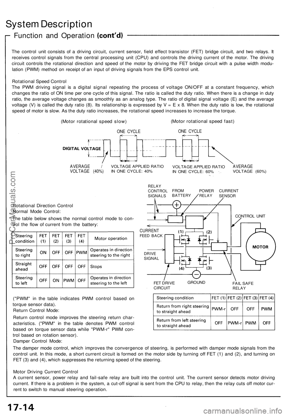
The control unit consists of a driving circuit, current sensor, field effect transistor (FET) bridge circuit, and two relays. It
receives control signals from the central processing unit (CPU) and controls the driving current of the motor. The driving
circuit controls the rotational direction and speed of the motor by driving the FET bridge circuit with a pulse width modu-
lation (PWM) method on receipt of an input of driving signals from the EPS control unit.
Rotational Speed Control
The PWM driving signal is a digital signal repeating the process of voltage ON/OFF at a constant frequency, which
changes the ratio of ON time per one cycle of this signal. The ratio is called the duty ratio. When there is a change in duty
ratio, the average voltage changes as smoothly as an analog type. The ratio of digital signal voltage (E) and the average
voltage (V) is called the duty ratio (8). Its relationship is expressed by V = E x 8. When the duty ratio is low, the rotational
speed of motor is slow. As the duty ratio increases, the rotational speed increases to increase the torque.
(Motor rotational speed slow)
ONE CYCLE
(Motor rotational speed fast)
ONE CYCLE
AVERAGE /
VOLTAGE (40%)
VOLTAGE APPLIED RATIO
IN ONE CYCLE: 40%
RELAY
CONTROL
SIGNALS
VOLTAGE APPLIED RATIO
IN ONE CYCLE: 60%
AVERAGE
VOLTAGE (60%)
FROM
BATTERY
POWER
RELAY
CURRENT
SENSOR
Rotational Direction Control
Normal Mode Control:
The table below shows the normal control mode to con-
trol the flow of current from the battery:
CURRENT
FEED BACK
DRIVE
SIGNAL
FET DRIVE
CIRCUIT
GROUND
FAIL SAFE
RELAY
("PWM" in the table indicates PWM control based on
torque sensor data).
Return Control Mode:
Return control mode improves the steering return char-
acteristics. ("PWM" in the table denotes PWM control
based on torque sensor data while "PWM-r" PWM con-
trol based on rotation sensor).
Damper Control Mode:
The damper mode control, which improves the convergence of steering, is performed with damper mode signals from the
control unit. In this mode, a short current circuit is formed on the motor side by turning off FET (1) and (2), and turning on
FET (3) and (4), which suppresses the returning speed of the steering.
Motor Driving Current Control
A current sensor, power relay and fail-safe relay are built into the control unit. The current sensor detects motor driving
current. If there is a problem in the system, a cut-off signal is sent from the CPU to relay, then the relay cuts off motor cur-
rent to switch to manual steering operation.
CONTROL UNITProCarManuals.com
Page 416 of 1640
Component Location s
GAUGE ASSEMBL Y
UNDER-HOO D FUSE /
RELAY BO X
TRANSMISSIO N CONTRO L
MODUL E (TCM )
22 P CONNECTO R
VEHICL E SPEE D SENSO R
(VSS)
(M/T)PULS E UNI T 7 P CONNECTO R
TORQU E SENSO R 6 P CONNECTOR /
ROTATIO N SENSO R
4 P CONNECTO R
STEERING GEARBO X
(TORQU E SENSOR /
ROTATIO N SENSOR )
UNDER-DASH FUS E BO X
EP
S CONTRO L UNI T
ALTERNATO R4P CONNECTO R
ProCarManuals.com
Page 417 of 1640
GAUGE ASSEMBLY
EPS INDICATOR LIGHT
UNDER-HOOD FUSE/RELAY BOX
No. 2 (15 A)
IG SW (50 A)
CLOCK (7.5 A)
E-PS
(50 A)
UNDER-DASH FUSE BOX
No. 5 (15 A)ProCarManuals.com
Page 422 of 1640
Diagnostic Trouble Code (DTC) Indication
Example:
1.3 seconds
DTC Indication Pattern:
DTC:
11
DTC:
12
EPS Indicator light ON
EPS Indicator light OFF
0.28 seconds
Repeat
Connect the SCS Turn the ignition
service connector switch ON (II)
0.36 seconds 1.3 seconds
• The DTC is indicated by a series of long and short blinks. One long blink equals 10 short blinks.
Add the long and short blinks together to determine the DTC.
• The DTCs are repeated sequentially beginning with the lowest number.
4. Remove the SCS service connector.
NOTE: The Malfunction Indicator Lamp (MIL) will stay on after the engine is started if the SCS service connector is
connected.
5. Remove the CLOCK (7.5 A) fuse in the under-hood fuse/relay box for more than 10 seconds to erase the EPS control
unit memory.ProCarManuals.com
Page 492 of 1640
Illustrated Index
The accumulator contains high-pressure nitrogen gas; do not puncture, expose to flame or attempt to
disassemble the accumulator or it may explode; severe personal injury may result.
HYDRAULIC SYSTEM
Relieving Accumulator/line pressure, page 19-62 ('91-'92) ('93-'96)
MASTER CYLINDER
Index/Torque, page 19-12
Inspection, page 19-13
ABS CONTROL UNIT Replacement, page 19-70
BRAKE BOOSTER
Tests, page 19-14 Pushrod clearance adjustment, page 19-15
UNDER-HOOD
RELAY BOX B
UNDER-HOOD
FUSE/RELAY BOX
REAR WHEEL SENSOR
Inspection, page 19-71
Replacement, page 19-72
POWER UNIT
Torque/Inspection, page 19-66
ACCUMULATOR/PRESSURE SWITCHIndex/Torque, page 19-67 FRONT WHEEL SENSOR
Inspection, page 19-71
Replacement, page 19-72
MODULATOR/SOLENOID UNIT
Index/Torque, page 19-63 ('91-'92) ('93-'96)
Solenoid Leak Test, page 19-64 ('91-'92) ('93-'96)
ProCarManuals.com
Page 517 of 1640

Anti-lock Brake System (ABS) Description
Features/Construction/Operation
General
In a conventional brake system, if the brake pedal is depressed excessively, the wheels can lock before the vehicle
comes to a stop. In such a case, the stability of the vehicle is reduced if the rear wheels are locked, and maneuverabily of
the vehicle is reduced if the front wheels are locked, creating an extremely unstable condition.
The Anti-lock Brake System (ABS) modulates the pressure of the brake fluid applied to each caliper, thereby preventing
the locking of the wheels, whenever the wheels are likely to be locked due to excessive braking. It then restores normal
hydraulic pressure when there is no longer any possibility of wheel locking.
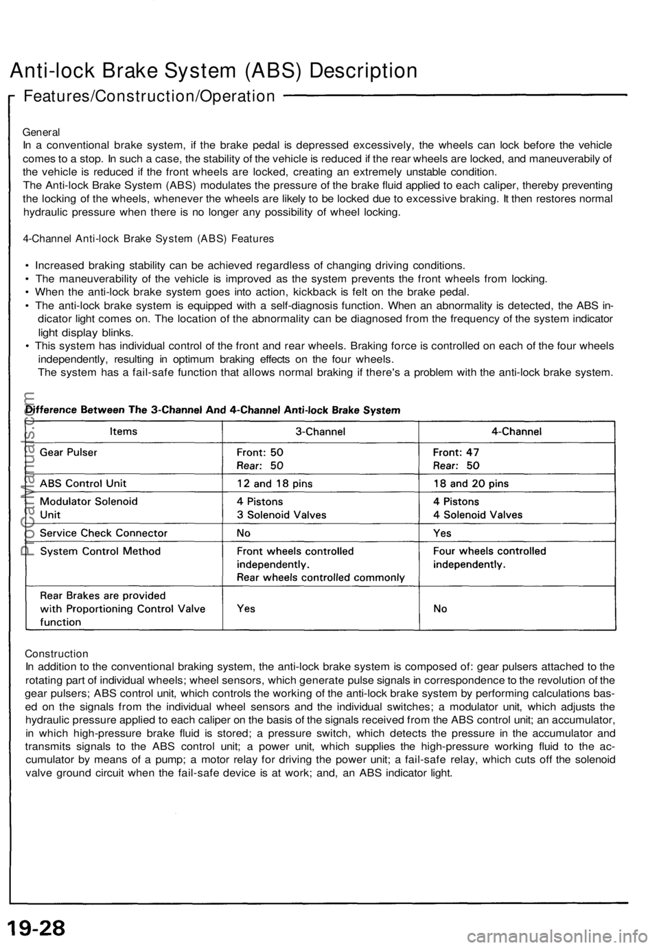
4-Channel Anti-lock Brake System (ABS) Features
• Increased braking stability can be achieved regardless of changing driving conditions.
• The maneuverability of the vehicle is improved as the system prevents the front wheels from locking.
• When the anti-lock brake system goes into action, kickback is felt on the brake pedal.
• The anti-lock brake system is equipped with a self-diagnosis function. When an abnormality is detected, the ABS in-
dicator light comes on. The location of the abnormality can be diagnosed from the frequency of the system indicator
light display blinks.
• This system has individual control of the front and rear wheels. Braking force is controlled on each of the four wheels
independently, resulting in optimum braking effects on the four wheels.
The system has a fail-safe function that allows normal braking if there's a problem with the anti-lock brake system.
Construction
In addition to the conventional braking system, the anti-lock brake system is composed of: gear pulsers attached to the
rotating part of individual wheels; wheel sensors, which generate pulse signals in correspondence to the revolution of the
gear pulsers; ABS control unit, which controls the working of the anti-lock brake system by performing calculations bas-
ed on the signals from the individual wheel sensors and the individual switches; a modulator unit, which adjusts the
hydraulic pressure applied to each caliper on the basis of the signals received from the ABS control unit; an accumulator,
in which high-pressure brake fluid is stored; a pressure switch, which detects the pressure in the accumulator and
transmits signals to the ABS control unit; a power unit, which supplies the high-pressure working fluid to the ac-
cumulator by means of a pump; a motor relay for driving the power unit; a fail-safe relay, which cuts off the solenoid
valve ground circuit when the fail-safe device is at work; and, an ABS indicator light.ProCarManuals.com