Page 769 of 1640
Charging System
Troubleshooting
Alternator/Regulator Test
Use the SUN VAT-40 (or equivalent) tester.
2. Attach the negative tester cable and the voltmeter
negative lead to the top of the intake manifold.
LOAD ADJUSTER
(CARBON PILE)
FULL FIELD
LEAD (BLU)
VOLTMETER
NEGATIVE
LEAD (BLK)
VOLT
SELECTOR
FIELD
SELECTOR
INDUCTIVE
PICK-UP
(GRN)
POSITIVE
CABLE (RED)
NEGATIVE
CABLE (BLK)
VOLTMETER
POSITIVE
LEAD (RED)
1. Attach the positive tester cable and the voltmeter
positive lead to the jump start terminal in the
engine compartment fuse/relay box.
POSITIVE CABLE
VOLTMETER
POSITIVE LEAD
JUMP
START
TERMINAL
- ENGINE COMPARTMENT
FUSE/RELAY BOX
VOLTMETER
NEGATIVE LEAD
NEGATIVE CABLE
NEGATIVE MARK
3. Attach the inductive pick-up to the B terminal wire
of the alternator with its arrow pointing away from
the terminal.
NOTE: The arrow must point away from the B
terminal.
INDUCTIVE PICK-UP
ARROW
ALTERNATOR
B TERMINAL
ALTERNATOR
TEST SELECTOR
SWITCHProCarManuals.com
Page 779 of 1640

Radiator and Condenser Fan Controls
Description
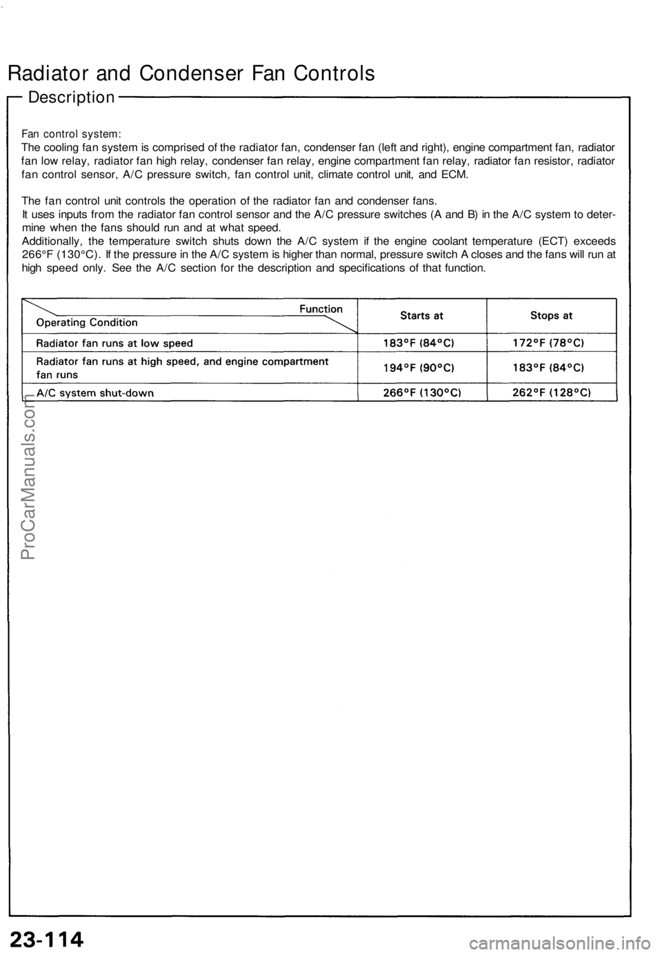
Fan control system:
The cooling fan system is comprised of the radiator fan, condenser fan (left and right), engine compartment fan, radiator
fan low relay, radiator fan high relay, condenser fan relay, engine compartment fan relay, radiator fan resistor, radiator
fan control sensor, A/C pressure switch, fan control unit, climate control unit, and ECM.
The fan control unit controls the operation of the radiator fan and condenser fans.
It uses inputs from the radiator fan control sensor and the A/C pressure switches (A and B) in the A/C system to deter-
mine when the fans should run and at what speed.
Additionally, the temperature switch shuts down the A/C system if the engine coolant temperature (ECT) exceeds
266°F (130°C). If the pressure in the A/C system is higher than normal, pressure switch A closes and the fans will run at
high speed only. See the A/C section for the description and specifications of that function.ProCarManuals.com
Page 781 of 1640
Radiator and Condenser Fan Controls
Control Unit Terminals
THROTTLE VALVE CONTROL
MOTOR RELAY
Wire
Terminal Color
Connects to
1. Disconnect the 3-P connector from the resistor.
RADIATOR
3-P CONNECTOR FAN
RESISTOR
NOT USED
2. Using an ohmmeter, measure resistance between
the A and B terminals. Replace the resistor if the
resistance is not within specifications.
NOTE: Resistance will vary with the resistor
temperature; specifications are at 68°F (20°C).
Radiator Fan Resistor
Resistance: 0.54—0.66 ohms
Radiator Fan Resistor Test
FAN CONTROL
UNITProCarManuals.com
Page 783 of 1640
Radiator an d Condense r Fa n Control s
Engine Compartmen t Fa n Moto r
Tes t (A/T )
1. Disconnec t th e 2- P connecto r fro m th e engin e
compartmen t fa n motor .
2 . Tes t th e moto r b y connectin g batter y powe r t o th e
A terminal , an d groun d t o th e B terminal .
3 . I f th e moto r fail s t o ru n o r doe s no t ru n smoothly ,
replac e it .
Engin e Compartmen t Fa n Moto r
Remova l (A/T )
1. Disconnec t th e 2- P connecto r fro m th e engin e
compartmen t fa n motor .
2 . Remov e th e engin e compartmen t fa n relay, the tes t
tachomete r connector , an d th e engin e wir e harnes s
fro m th e engin e compartmen t fa n shroud .
3 . Remov e th e thre e mountin g bolts .
MOUNTIN G BOL T6 x 1 0 m m12 N- m (1. 2 kg-m , 9 Ib-ft ) TES
T TACHOMETE RCONNECTOR
WASHER(Corrosio nresistant)
ENGIN E COMPARTMEN T
FAN RELA Y
2-P CONNECTO R
ProCarManuals.com
Page 784 of 1640
Fan Relay Tests
Check continuity at the relay terminals.
• There should be continuity between the C and D ter-
minals.
• There should be continuity between the A and B ter-
minals when power and ground are connected to the
C and D terminals.
• There should be no continuity between the A and B
terminals when power is disconnected.
• Radiator fan low relay
• Radiator fan high relay
• Condenser fan relay
Engine compartment fan relay (A/T)ProCarManuals.com
Page 805 of 1640

Safety Indicator
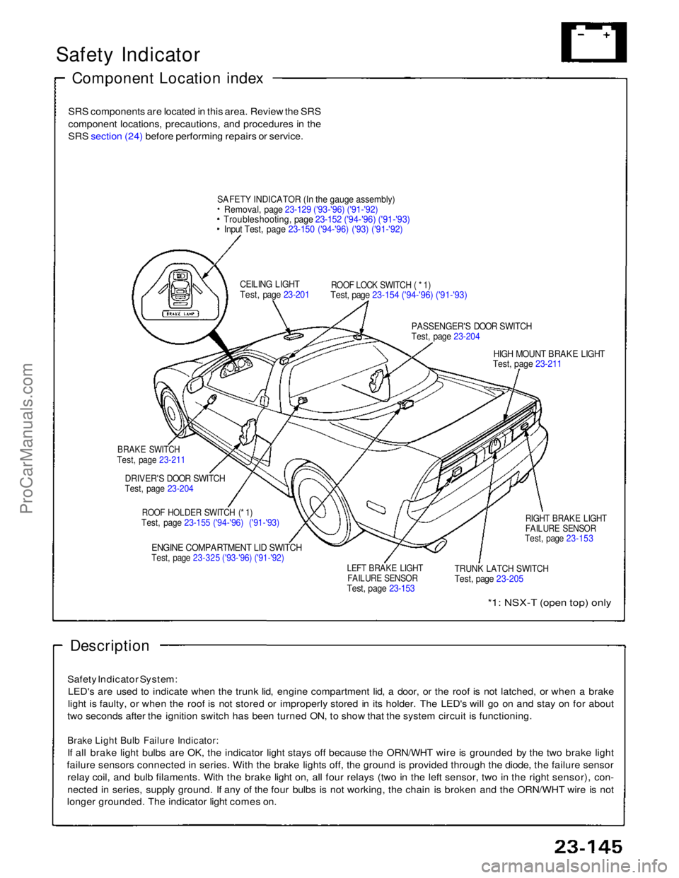
Component Location index
SRS components are located in this area. Review the SRS
component locations, precautions, and procedures in the
SRS section (24) before performing repairs or service.
SAFET
Y
INDICATOR (In the gauge assembly)
Removal, page 23-129 ('93-'96) ('91-'92)
Troubleshooting, page 23-152 ('94-'96) ('91-'93)
Input Test, page 23-150 ('94-'96) ('93) ('91-'92)
CEILING LIGHT
Test, page 23-201
ROOF LOCK SWITCH ( * 1)
Test, page 23-154 ('94-'96) ('91-'93)
PASSENGER'S DOOR SWITCH
Test, page 23-204
HIGH MOUNT BRAKE LIGHT
Test, page 23-211
BRAKE SWITCH
Test, page 23-211
DRIVER'S DOOR SWITCH
Test, page 23-204
ROOF HOLDER SWITCH (* 1)
Test, page 23-155 ('94-'96) ('91-'93)
ENGINE COMPARTMENT LID SWITCH
Test, page 23-325 ('93-'96) ('91-'92)
LEFT BRAKE LIGHT
FAILURE SENSOR
Test, page 23-153
TRUNK LATCH SWITCH
Test, page 23-205
RIGHT BRAKE LIGHT
FAILURE SENSOR
Test, page 23-153
*1: NSX-T (open top) only
Description
Safety Indicator System: LED's are used to indicate when the trunk lid, engine compartment lid, a door, or the roof is not latched, or when a brake
light is faulty, or when the roof is not stored or improperly stored in its holder. The LED's will go on and stay on for about
two seconds after the ignition switch has been turned ON, to show that the system circuit is functioning.
Brake Light Bulb Failure Indicator:
If all brake light bulbs are OK, the indicator light stays off because the ORN/WHT wire is grounded by the two brake light
failure sensors connected in series. With the brake lights off, the ground is provided through the diode, the failure sensor relay coil, and bulb filaments. With the brake light on, all four relays (two in the left sensor, two in the right sensor), con-
nected in series, supply ground. If any of the four bulbs is not working, the chain is broken and the ORN/WHT wire is not
longer grounded. The indicator light comes on.ProCarManuals.com
Page 826 of 1640
UNDER-HOOD FUSE/RELAY BOX
UNDER-HOOD RELAY BOX A
DIMMER RELAY
Test, page 23-189
TAILLIGHT RELAYTest, page 23-190
('94-'96) ('91-'93) LEFT HEADLIGHT
RETRACTOR CUT RELAY
Test page 23-190 ('94-'96) ('91-'93)
RIGHT HEADLIGHTRETRACTOR CUT RELAYTest, page 23-190 ('94-'96) ('91-'93)
HEADLIGHT RELAY
Test, page 23-189
RIGHT HEADLIGHT
RETRACTOR RELAY
Test page 23-190
('94-'96) ('91-'93)
RIGHT HEADLIGHT
RETRACTOR MOTOR
Test, page 23-188
Replacement, page
23-186
RIGHT DAYTIME RUNNING
LIGHT (Canada)
Replacement, page, 23-194 HEADLIGHTS
Adjustment, page 23-192
Replacement page 23-163
LEFT DAYTIME RUNNING LIGHT (Canada)
Replacement, page 23-194
LEFT HEADLIGHT
RETRACTOR MOTOR
Test, page 23-186 Replacement, page 23-186 LEFT HEADLIGHT
RETRACTOR RELAY
Test, page 23-190
('94-'96) ('91-'93)ProCarManuals.com
Page 836 of 1640
Lighting System
Retractor Motor Replacement
CAUTION:
• Halogen headlights can become very hot in use; do
not touch them or the attaching hardware immediately
after they have been turned off.
• Do not try to replace or clean headlights with the lights
on.
1. Remove the No. 42 (15 A) and No. 43 (15 A) fuses
from the under-hood fuse/relay box.
No. 43
(15A)
FUSE
No. 42
(15A)
FUSE
UNDER-HOOD FUSE/RELAY BOX
2. Turn the knob clockwise to raise the headlight.
CAP
KNOB
3. Remove the two caps, four screws, and cowl clips.
COWL CLIP
CAP
SCREW
4. Slide the headlight housing forward and up.
NOTE: Be careful not to damage the front bumper
or the headlight housing.
HEADLIGHT HOUSING
PROTECTIVE TAPE
5. Disconnect the 6-P connector from the headlight
unit.
6-P CONNECTOR
HEADLIGHT UNIT
6. Remove the four mounting bolts, then remove the
unit.
MOUNTING
BOLTSProCarManuals.com