Page 237 of 1640
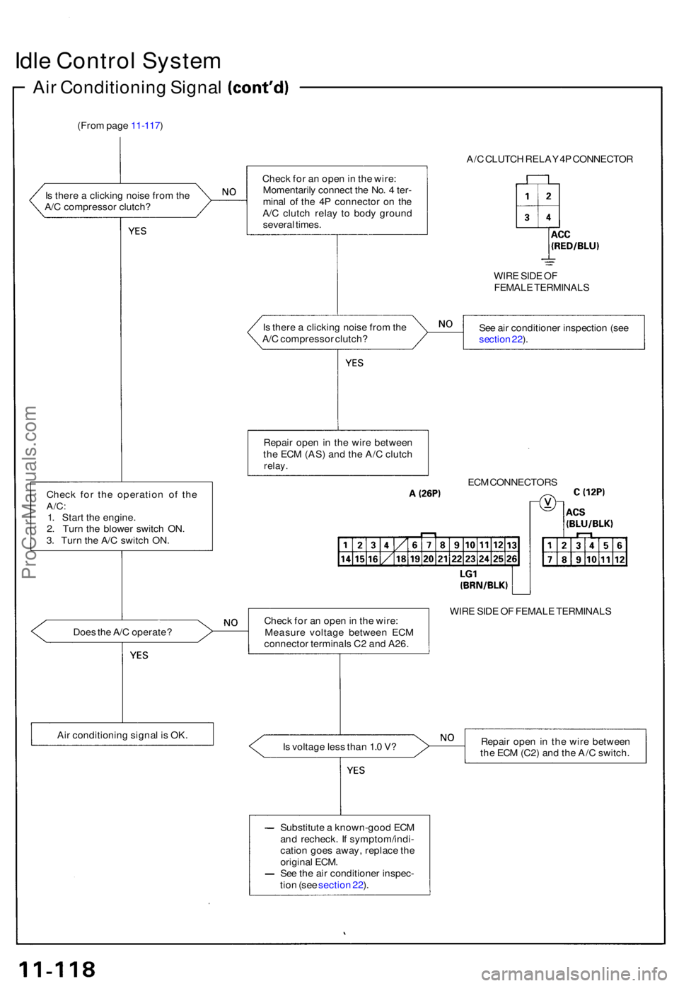
Idle Contro l Syste m
Air Conditionin g Signa l
(From pag e 11-117 )
I s ther e a clickin g nois e fro m th e
A/ C compresso r clutch ?
Chec k fo r th e operatio n o f th e
A/C :1. Star t th e engine .
2 . Tur n th e blowe r switc h ON .
3 . Tur n th e A/ C switc h ON .
Doe s th e A/ C operate ?
Ai r conditionin g signa l i s OK . A/
C CLUTC H RELA Y 4P CONNECTO R
Chec k fo r a n ope n in th e wire :
Momentaril y connec t th e No . 4 ter -
mina l o f th e 4 P connecto r o n th e
A/ C clutc h rela y t o bod y groun d
severa l times .
WIRE SID E O F
FEMAL E TERMINAL S
I s ther e a clickin g nois e fro m th e
A/ C compresso r clutch ? Se
e ai r conditione r inspectio n (se e
sectio n 22 ).
Repai r ope n in th e wir e betwee n
th e EC M (AS ) an d th e A/ C clutc h
relay.
ECM CONNECTOR S
Chec k fo r a n ope n in th e wire :
Measur e voltag e betwee n EC M
connecto r terminal s C 2 an d A26 . WIR
E SID E O F FEMAL E TERMINAL S
I s voltag e les s tha n 1. 0 V ? Repai
r ope n in th e wir e betwee n
th e EC M (C2 ) an d th e A/ C switch .
Substitut e a known-goo d EC M
an d recheck . I f symptom/indi -
catio n goe s away , replac e th e
origina l ECM .
Se e th e ai r conditione r inspec -
tio n (se e sectio n 22 ).
ProCarManuals.com
Page 246 of 1640
Starter Switch Signal
This signals the ECM when the engine is cranking.
Inspection of Starter Switch Sig-
nal.
NOTE:
• M/T: Clutch pedal must be depressed.
• A/T: Transmission in position.
ECM CONNECTORS
Measure voltage between ECM
connector terminals C6 and A26
with the ignition switch in the
start position.
WIRE SIDE OF FEMALE TERMINALS
Is there battery voltage?
Is the fuse OK?
Repair short in the wire
between the ECM (C6) and
the No. 7 STARTER SIGNAL
(7.5 A) fuse or the PGM-FI
main relay.
Replace the No. 7 STARTER
SIGNAL (7.5 A) fuse.
Starter switch signal is OK.
Repair open in the wire between
the ECM
(C6)
and the No. 7
STARTER SIGNAL (7.5 A) fuse.
Inspect the No. 7 STARTER SIG-
NAL (7.5 A) fuse in the under-
dash fuse box.ProCarManuals.com
Page 259 of 1640

Fuel Pum p Rela y
Troubleshootin g Flowchar t
Inspection o f fue l pum p relay .
Tur n th e ignitio n switc h t o STAR T
(III) position .
Does th e engin e start ?
Chec k fo r a n ope n in th e circuit :
1 . Sto p th e engine .
2. Tur n th e ignitio n switc h O N (II) .3. Measur e voltag e betwee n
EC M connecto r termina l F 4
an d bod y ground .
I s ther e batter y voltage ?
Proble m verification :
1 . Star t th e engine . Hol d th e
engin e a t 3,00 0 rp m wit h n o
loa d (A/ T in position ,M/T in neutral ) unti l th e radia -
to r fa n come s on , the n le t i t
idl e fo r a t leas t on e minute .
2. Tur n th e ignitio n switc h OFF .3. Disconnec t # 4 hos e fro m th e
instal l pipe , connec t vacuu m
pum p t o th e hose .
4 . Appl y vacuu m 2 7 t o 4 0 kp a
(200 t o 300 mmHg , 8 to 1 2in.Hg) .
5 . Star t th e engine .
6 . Hol d engin e spee d a t 6,50 0
rpm (A/ T in position ,M/T in neutral) .
7 . Measur e voltag e betwee n
EC M connecto r termina l F 4
an d bod y ground .
I s ther e les s tha n 1. 0 V ? Inspec
t th e fue l pum p resisto r
(se e pag e 11-141 ).
ECM CONNECTO R F (26P )
WIR E SID E O F FEMAL E TERMINAL S
(T o pag e 11-140 )
4 HOS E
CONTRO LBOX
VACUU M PUMP /GAUGEA973X-04 1-XXXX X
Substitut e a known-goo d EC M
an d recheck . I f prescribe d volt -
ag e i s no w available , replac e th e
origina l ECM .
Fue l pum p rela y circui t i s OK .
ProCarManuals.com
Page 260 of 1640
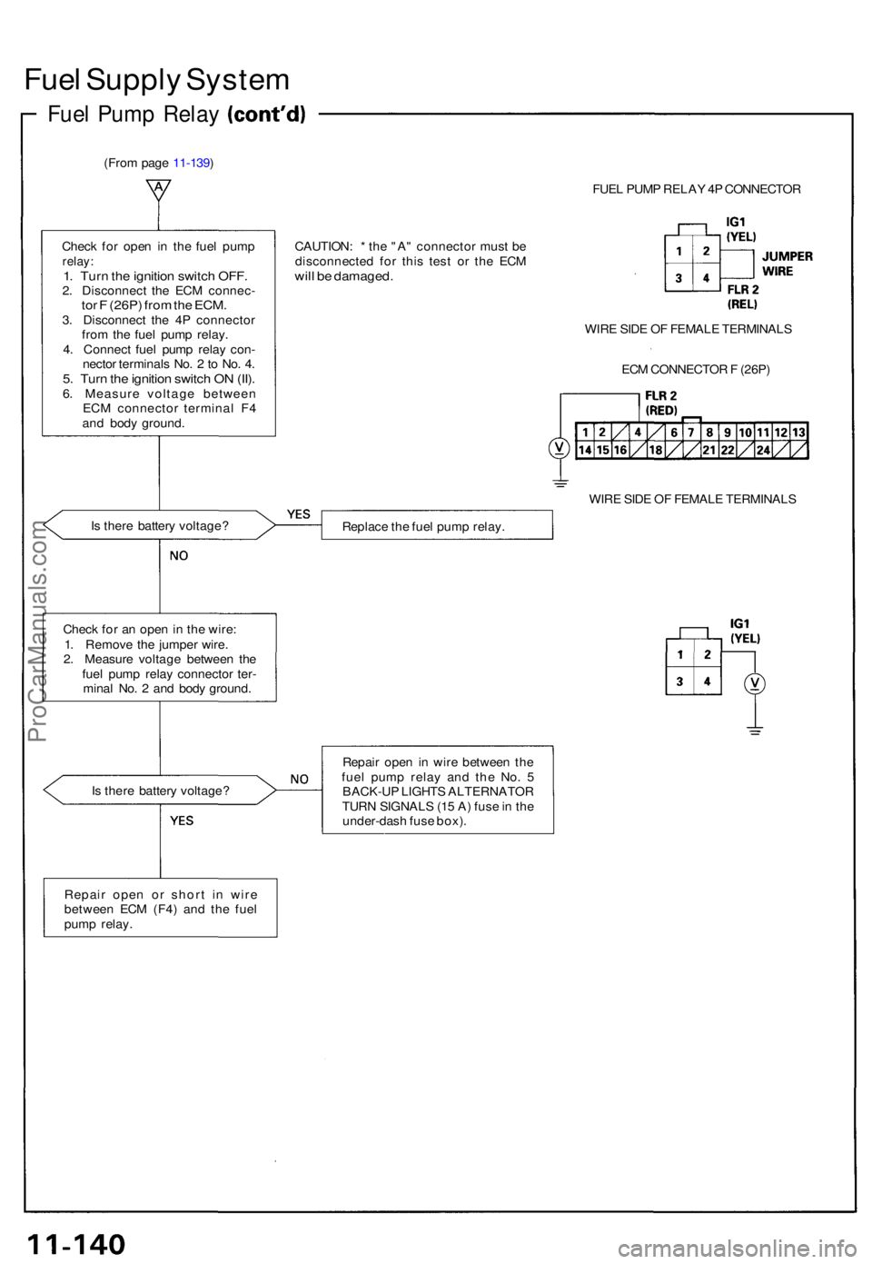
Fuel Suppl y Syste m
Fuel Pum p Rela y
(From pag e 11-139 )
FUEL PUM P RELA Y 4 P CONNECTO R
Chec k fo r ope n i n th e fue l pum p
relay:1. Tur n th e ignitio n switc h OFF .2. Disconnec t th e EC M connec -tor F (26P ) fro m th e ECM .3. Disconnec t th e 4 P connecto r
fro m th e fue l pum p relay .
4 . Connec t fue l pum p rela y con -
necto r terminal s No . 2 to No . 4 .
5. Tur n th e ignitio n switc h O N (II) .6. Measur e voltag e betwee n
EC M connecto r termina l F 4
an d bod y ground . CAUTION
: * th e "A " connecto r mus t b e
disconnecte d fo r thi s tes t o r th e EC M
will b e damaged .
WIRE SID E O F FEMAL E TERMINAL S
EC M CONNECTO R F (26P )
WIR E SID E O F FEMAL E TERMINAL S
I s ther e batter y voltage ?
Replace th e fue l pum p relay .
Chec k fo r a n ope n in th e wire :
1 . Remov e th e jumpe r wire .
2 . Measur e voltag e betwee n th e
fue l pum p rela y connecto r ter -
mina l No . 2 an d bod y ground .
I s ther e batter y voltage ? Repai
r ope n i n wir e betwee n th e
fue l pum p rela y an d th e No . 5
BACK-U P LIGHT S ALTERNATO R
TUR N SIGNAL S (1 5 A ) fus e in th e
under-das h fus e box) .
Repai r ope n o r shor t i n wir e
betwee n EC M (F4 ) an d th e fue l
pum p relay .
ProCarManuals.com
Page 261 of 1640
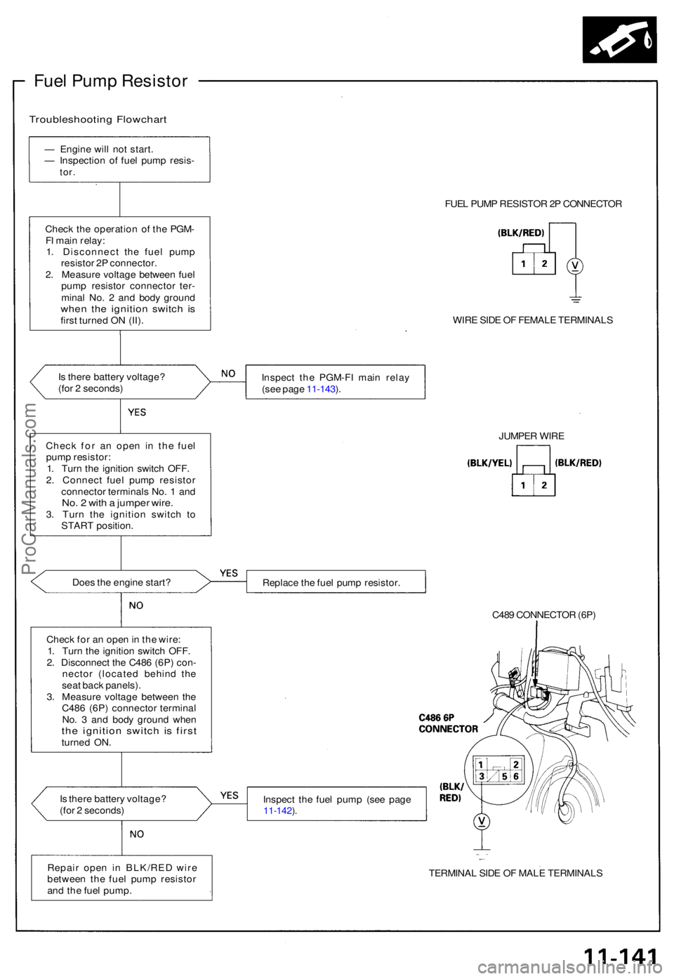
Fuel Pum p Resisto r
Troubleshootin g Flowchar t
— Engin e wil l no t start .
— Inspectio n o f fue l pum p resis -
tor.
Chec k th e operatio n o f th e PGM -
F I mai n relay :
1 . Disconnec t th e fue l pum p
resisto r 2 P connector .
2 . Measur e voltag e betwee n fue l
pum p resisto r connecto r ter -
mina l No . 2 an d bod y groun d
when th e ignitio n switc h i sfirs t turne d O N (II) .
I s ther e batter y voltage ?
(fo r 2 seconds )
Doe s th e engin e start ?
Chec k fo r a n ope n in th e wire :
1 . Tur n th e ignitio n switc h OFF .
2 . Disconnec t th e C48 6 (6P ) con -
necto r (locate d behin d th e
sea t bac k panels) .
3 . Measur e voltag e betwee n th e
C48 6 (6P ) connecto r termina l
No . 3 an d bod y groun d whe n
the ignitio n switc h i s firs tturne d ON .
I s ther e batter y voltage ?
(fo r 2 seconds ) FUE
L PUM P RESISTO R 2P CONNECTO R
WIR E SID E O F FEMAL E TERMINAL S
Inspec t th e PGM-F I mai n rela y
(se e pag e 11-143 ).
Replac e th e fue l pum p resistor .
C489 CONNECTO R (6P )
Inspec t th e fue l pum p (se e pag e
11-142 ).
TERMINA L SID E O F MAL E TERMINAL S
JUMPE
R WIR E
Chec k fo r a n ope n i n th e fue l
pum p resistor :
1 . Tur n th e ignitio n switc h OFF .
2 . Connec t fue l pum p resisto r
connecto r terminal s No . 1 an d
No. 2 wit h a jumpe r wire .3. Tur n th e ignitio n switc h t o
STAR T position .
Repai r ope n i n BLK/RE D wir e
betwee n th e fue l pum p resisto r
an d th e fue l pump .
ProCarManuals.com
Page 263 of 1640
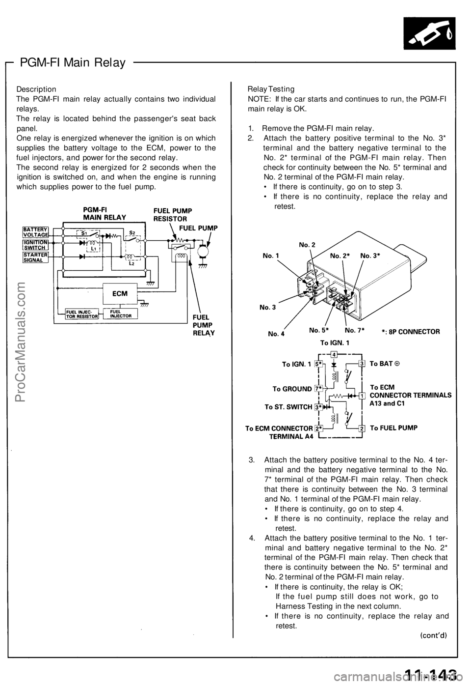
PGM-FI Mai n Rela y
Descriptio n
Th e PGM-F I mai n rela y actuall y contain s tw o individua l
relays .
Th e rela y i s locate d behin d th e passenger' s sea t bac k
panel .
On e rela y i s energize d wheneve r th e ignitio n i s o n whic h
supplie s th e batter y voltag e t o th e ECM , powe r t o th e
fue l injectors , an d powe r fo r th e secon d relay .
Th e secon d rela y i s energize d fo r 2 second s whe n th e
ignitio n i s switche d on , an d whe n th e engin e i s runnin g
whic h supplie s powe r t o th e fue l pump . Rela
y Testin g
NOTE : I f th e ca r start s an d continue s t o run , th e PGM-F I
mai n rela y is OK .
1 . Remov e th e PGM-F I mai n relay .
2 . Attac h th e batter y positiv e termina l t o th e No . 3 *
termina l an d th e batter y negativ e termina l t o th e
No . 2 * termina l o f th e PGM-F I mai n relay . The n
chec k fo r continuit y betwee n th e No . 5 * termina l an d
No . 2 termina l o f th e PGM-F I mai n relay .
• I f ther e i s continuity , g o o n t o ste p 3 .
• I f ther e i s n o continuity , replac e th e rela y an d
retest .
3 . Attac h th e batter y positiv e termina l t o th e No . 4 ter -
mina l an d th e batter y negativ e termina l t o th e No .
7 * termina l o f th e PGM-F I mai n relay . The n chec k
tha t ther e i s continuit y betwee n th e No . 3 termina l
an d No . 1 termina l o f th e PGM-F I mai n relay .
• I f ther e is continuity , g o o n t o ste p 4 .
• I f ther e i s n o continuity , replac e th e rela y an d
retest .
4 . Attac h th e batter y positiv e termina l t o th e No . 1 ter -
mina l an d batter y negativ e termina l t o th e No . 2 *
termina l o f th e PGM-F I mai n relay . The n chec k tha t
ther e i s continuit y betwee n th e No . 5 * termina l an d
No . 2 termina l o f th e PGM-F I mai n relay .
• I f ther e i s continuity , th e rela y i s OK ;
I f th e fue l pum p stil l doe s no t work , g o t o
Harnes s Testin g in th e nex t column .
• I f ther e i s n o continuity , replac e th e rela y an d
retest .
ProCarManuals.com
Page 265 of 1640
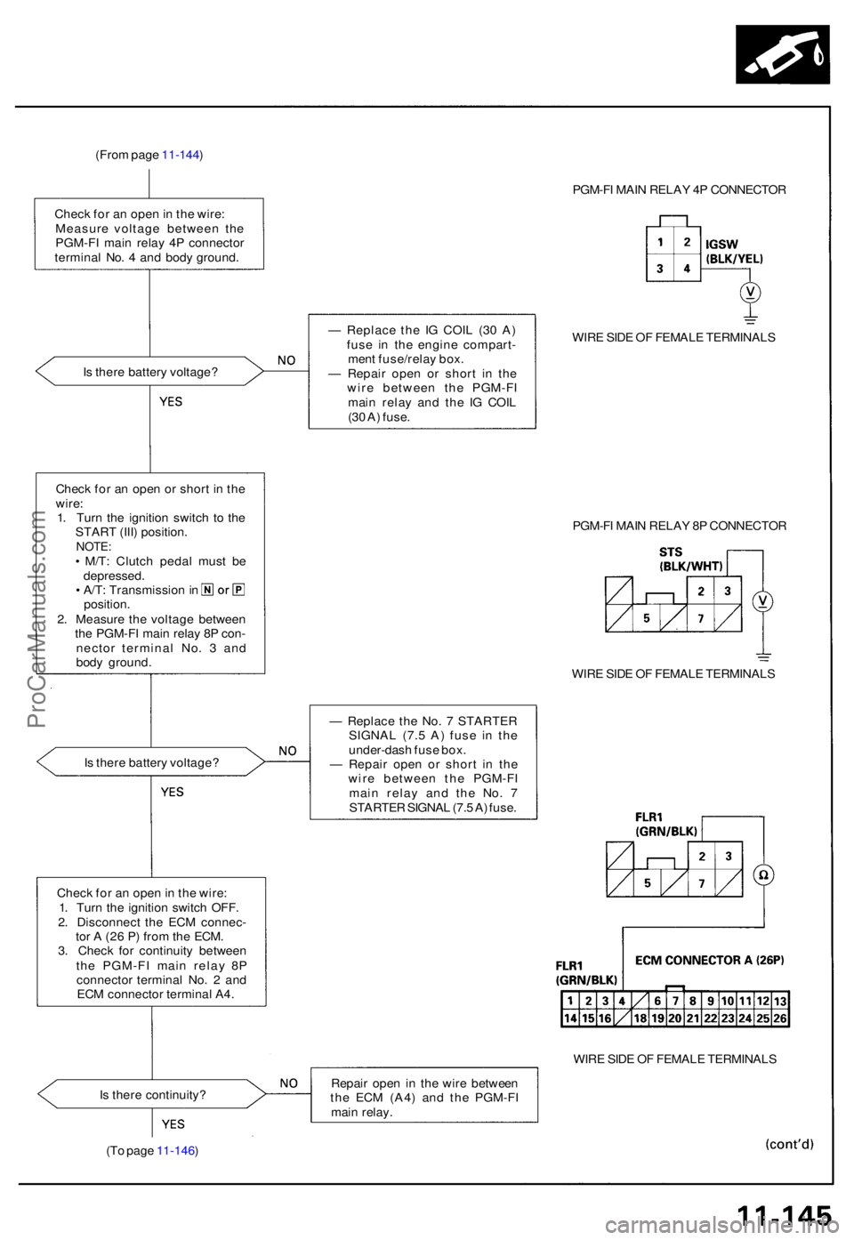
(From pag e 11-144 )
Chec k fo r a n ope n in th e wire :
Measur e voltag e betwee n th e
PGM-F I mai n rela y 4 P connecto r
termina l No . 4 an d bod y ground . PGM-F
I MAI N RELA Y 4 P CONNECTO R
I s ther e batter y voltage ? —
Replac e th e I G COI L (3 0 A )
fus e i n th e engin e compart -
men t fuse/rela y box .
— Repai r ope n o r shor t i n th e
wir e betwee n th e PGM-F I
mai n rela y an d th e I G COI L
(3 0 A ) fuse . WIR
E SID E O F FEMAL E TERMINAL S
Chec k fo r a n ope n o r shor t i n th e
wire :
1 . Tur n th e ignitio n switc h t o th e
STAR T (III ) position .
NOTE:• M/T : Clutc h peda l mus t b e
depressed .
• A/T : Transmissio n in
position .
2 . Measur e th e voltag e betwee n
th e PGM-F I mai n rela y 8 P con -
necto r termina l No . 3 an d
bod y ground . PGM-F
I MAI N RELA Y 8 P CONNECTO R
WIR E SID E O F FEMAL E TERMINAL S
I s ther e batter y voltage ? —
Replac e th e No . 7 STARTE R
SIGNA L (7. 5 A ) fus e i n th e
under-das h fus e box .
— Repai r ope n o r shor t i n th e
wir e betwee n th e PGM-F I
mai n rela y an d th e No . 7
STARTE R SIGNA L (7. 5 A ) fuse .
Chec k fo r a n ope n in th e wire :
1 . Tur n th e ignitio n switc h OFF .
2 . Disconnec t th e EC M connec -
to r A (2 6 P ) fro m th e ECM .
3 . Chec k fo r continuit y betwee n
th e PGM-F I mai n rela y 8 P
connecto r termina l No . 2 an d
EC M connecto r termina l A4 .
WIRE SID E O F FEMAL E TERMINAL S
I s ther e continuity ? Repai
r ope n i n th e wir e betwee n
th e EC M (A4 ) an d th e PGM-F I
mai n relay .
(T o pag e 11-146 )
ProCarManuals.com
Page 266 of 1640
Fuel Suppl y Syste m
PGM-F I Mai n Rela y
(From pag e 11-145 )
Chec k fo r a n ope n in th e wire :
1 . Reconnec t th e EC M connecto r
A (26P) .2. Reconnec t th e PGM-F I mai n
rela y 4 P an d 8 P connectors .
3 . Tur n th e ignitio n switc h O N (II) .
4 . Measur e voltag e betwee n
EC M connecto r terminal s
A13, C1, an d A12 .
ECM CONNECTOR S
WIRE SID E O F FEMAL E TERMINAL S
I s ther e batter y voltage ? Repai
r ope n i n th e wir e
betwee n th e EC M (A13 , C D
an d th e PGM-F I mai n relay .
Replac e th e PGM-F I mai n
relay.
Chec k fo r a n ope n in th e ECM :
1 . Tur n th e ignitio n switc h OFF .
2 . Measur e voltag e betwee n
EC M connecto r terminal s A 4
an d A1 2 whe n th e ignitio n
switc h i s firs t turne d o n fo r
tw o seconds .
Is ther e 1. 0 V or less ?
Substitut e a known-goo d EC M
an d recheck . I f prescribe d volt -
ag e is no w available , replac e th e
origina l ECM .
Chec k th e PGM-F I mai n rela y
(se e pag e 11-143 ).
ProCarManuals.com