Page 1575 of 1640

Solenoid Flushing
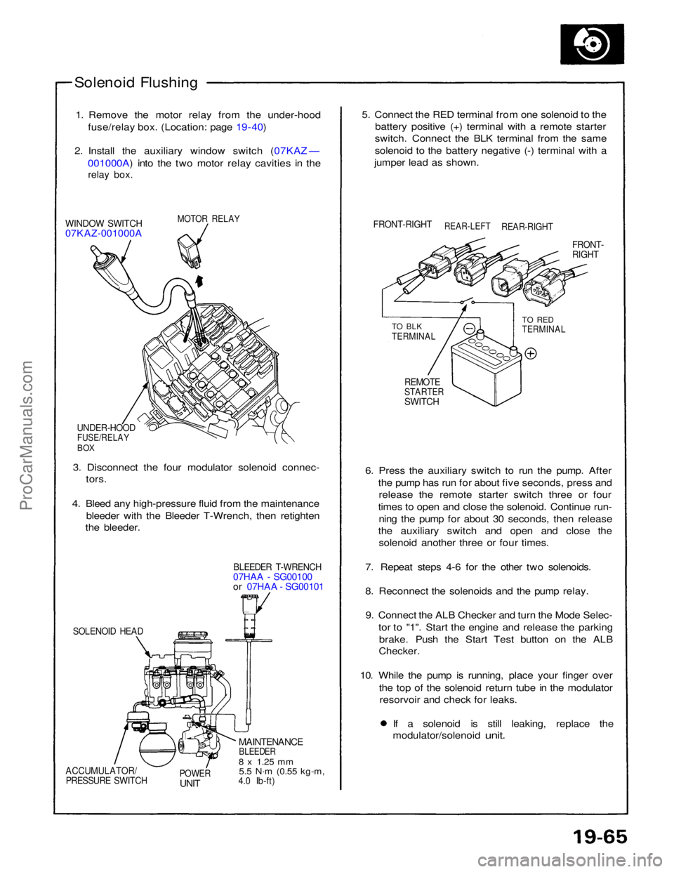
1. Remove the motor relay from the under-hood fuse/relay box. (Location: page 19 - 40)
2. Install the auxiliary window switch (07KAZ — 001000A) into the two motor relay cavities in the
relay box.
MOTOR RELAY
WINDOW SWITCH
07KAZ-001000A
UNDER-HOOD
FUSE/RELAY
BOX
3. Disconnect the four modulator solenoid connec- tors.
4. Bleed any high-pressure fluid from the maintenance bleeder with the Bleeder T-Wrench, then retighten
the bleeder.
BLEEDER T-WRENCH
07HAA - SG00100
or 07HAA - SG00101
SOLENOID HEAD
MAINTENANCE
BLEEDER
8 x
1.25
mm
5.5 N·m
(0.55 kg-m,
4.0 Ib-ft)
POWER
UNIT
ACCUMULATOR/
PRESSURE SWITCH
6. Press the auxiliary switch to run the pump. After
the pump has run for about five seconds, press andrelease the remote starter switch three or four
times to open and close the solenoid. Continue run- ning the pump for about 30 seconds, then release
the auxiliary switch and open and close the solenoid another three or four times.
7. Repeat steps 4-6 for the other two solenoids.
8. Reconnect the solenoids and the pump relay. 9. Connect the ALB Checker and turn the Mode Selec- tor to "1". Start the engine and release the parkingbrake. Push the Start Test button on the ALB
Checker.
10. While the pump is running, place your finger over the top of the solenoid return tube in the modulatorresorvoir and check for leaks. If a solenoid is still leaking, replace the
modulator/solenoid
unit.
REMOTE
STARTER
SWITCH
TO BLK
TERMINAL
TO RED
TERMINAL
FRONT-
RIGHT
FRONT-RIGHT
REAR-LEFT
REAR-RIGHT
5. Connect the RED terminal from one solenoid to the
battery positive (+) terminal with a remote starter
switch. Connect the BLK terminal from the same
solenoid to the battery negative (-) terminal with a
jumper lead as shown.ProCarManuals.com
Page 1590 of 1640

Radiator and Condenser Fan Controls
Description
Fan control system:
The cooling fan system is comprised of radiator fan, condenser fan (left, right), engine compartment fan, radiator fan
low relay, radiator fan high relay, condenser fan relay, engine room fan relay, radiator fan resistor, coolant temperature
sensor, A/C pressure switch, cooling fan control unit, climate control unit, and PGM-FI ECU.
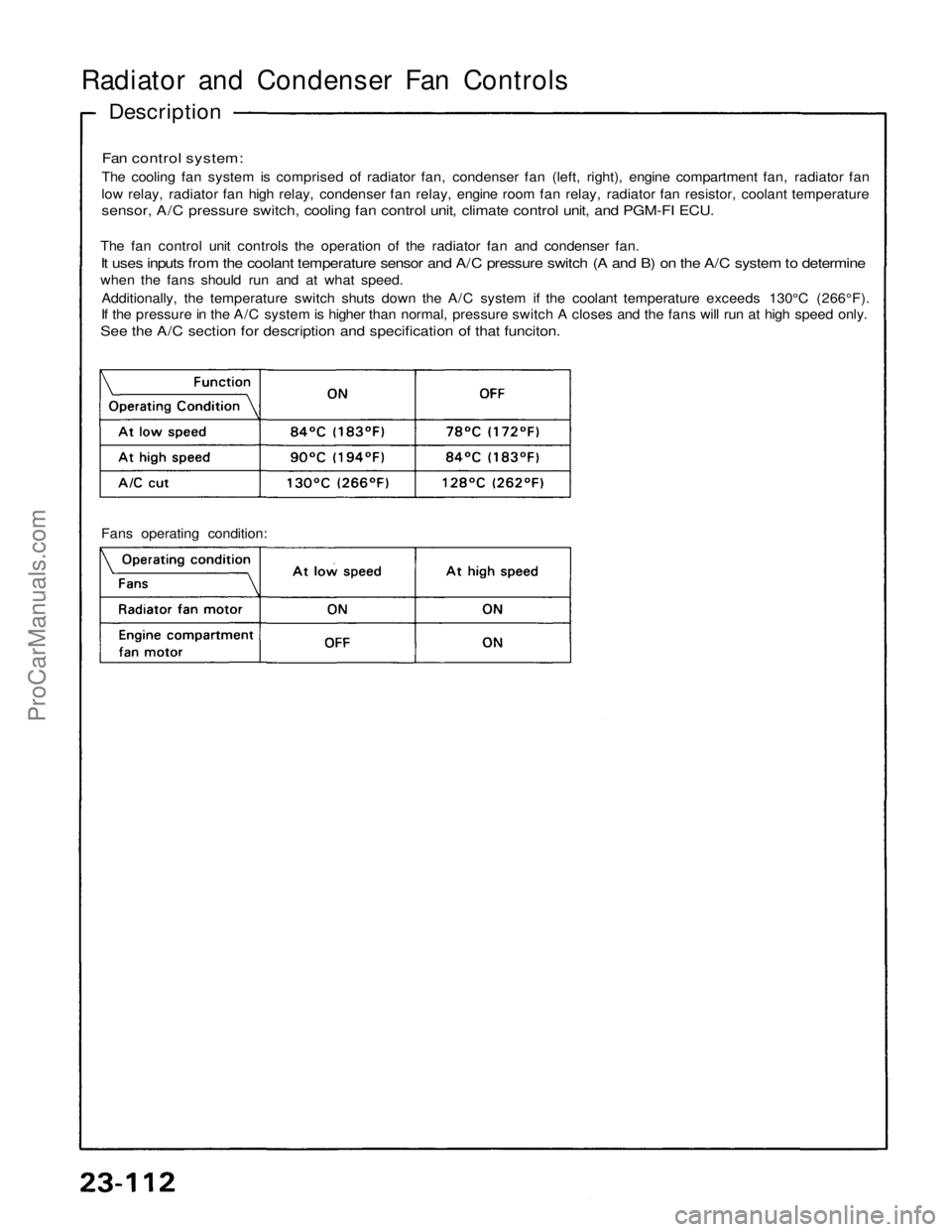
The fan control unit controls the operation of the radiator fan and condenser fan.
It uses inputs from the coolant temperature sensor and A/C pressure switch (A and B) on the A/C system to determine
when the fans should run and at what speed.
Additionally, the temperature switch shuts down the A/C system if the coolant temperature exceeds 130°C (266°F).
If the pressure in the A/C system is higher than normal, pressure switch A closes and the fans will run at high speed only.
See the A/C section for description and specification of that funciton.
Fans operating condition:ProCarManuals.com
Page 1611 of 1640
Side Marker/Turn Signal/Hazard Flash System
Turn Signal/Hazard Relay Input Test
Remove the dashboard lower cover.
Remove the turn signal/hazard relay from the left kick
panel then disconnect the 6-P connector.
Make the following input tests at the 6-P connector ter-
minals.
If all tests prove OK, but the relay fails to work, replace
the turn signal/hazard relay.
View from
terminal side
TURN SIGNAL/
HAZARD RELAYProCarManuals.com
Page 1618 of 1640
CAUTION:
All SRS electrical wiring harnesses are covered with
yellow outer insulation.
Before disconnecting the SRS wire harness, install
the short connector on the airbag (see page 23-323). Replace the entire affected SRS harness assembly
if it has an open circuit or damaged wiring.
SRS MAIN WIRE HARNESS
DEFOGGER SWITCH
Removal, page 23-273
Test, page 23-275
REAR WINDOW DEFOGGER
Function Test, page 23-288
UNDER-DASH FUSE BOX
INTEGRATED
CONTROL UNIT
DEFOGGER
RELAY
ENGINE COMPARTMENT FUSE/RELAY BOX
Description Function:
The rear window defogger is controlled by the integrated control unit.
When the defogger switch in the combination switch is pushed, it sends a signal to the defogger timer in the integrated
contro
l
unit and the defogger stays on for 25 minutes or until the ignition swi\
tch is switched off.
The indicator light in the switch shows when the defogger is on.
Rear Window Defogger
Component
Location Index
ProCarManuals.com
Page 1621 of 1640
Troubleshooting
NOTE: The numbers in the table show the troubleshooting sequence.
Intermittent Relay Test
1. Remove the wiper intermittent relay from sub relay
box B.
2. There should be continuity between the A and C ter-
minals when the battery is connected to the E and
F terminals.
The should be continuity between the B and C ter-
minals when the battery is disconnected.ProCarManuals.com
Page 1626 of 1640
Troubleshooting
NOTE:
The numbers in the table show the troubleshooting sequence.
Before troubleshooting.
Check the No. 5 (10A) fuse in the under-dash fuse box, and the No. 29 (50A), No. 45 (20A) fuses in the under-
hood fuse/relay box.
Check that the horns sound.
Check the tachometer for proper operation.ProCarManuals.com