Page 1441 of 1640
Troubleshooting
NOTE:
The numbers in the table show the troubleshooting sequence.
Before troubleshooting.
Check the No. 5 (10 A) fuse in the under-dash fuse box, and the No. 29 (50 A) and No. 45 (20 A) fuses in the
under-hood fuse/relay box.
Check that the horns sound.
Check that the tachometer works properly.ProCarManuals.com
Page 1464 of 1640
Component Locations
Index
FRONT KNOCK SENSOR
Troubleshooting, page 11-62
COOLANT TEMPERATURE (TW) SENSOR
Troubleshooting, page 11 - 48
EGR VALVE
Troubleshooting,
page 11-128
FUEL PUMP RESISTOR
Inspection, page 11-106
CRANK/CYL SENSOR
Troubleshooting, page 11-46
CONTROL BOX
page 11-6 THROTTLE
ANGLE
SENSOR
Troubleshooting,
page 11-50
FAST IDLE VALVE
Inspection, page 11-83
EACV
Troubleshooting,
page 11-70 INJECTOR
RESISTOR
Testing, page 11-94
FRONT HEATED
OXYGEN (O2) SENSOR
Troubleshooting, page 11-32
INTAKE AIR TEMPERATURE
(TA) SENSOR
Troubleshooting, page 11-52
REAR KNOCK SENSOR
Troubleshooting, page 11 -62
REAR HEATED
OXYGEN (O2) SENSOR
Troubleshooting, page 11 -32
MAIN RELAY
Relay Testing, page 11-104
Inspection, page 11-105
ELECTRONIC CONTROL UNIT (ECU)
Troubleshooting, page 11-26
FUEL PUMP RELAY
Inspection, page 11-99ProCarManuals.com
Page 1480 of 1640

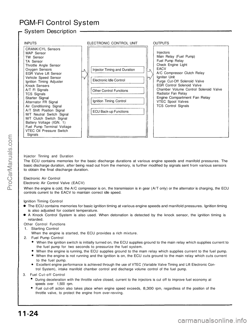
PGM-FI Control System
System Description
INPUTS ELECTRONIC CONTROL UNIT OUTPUTSCRANK/CYL SensorsMAP Sensor
TW Sensor
TA Sensor
Throttle Angle Sensor Oxygen SensorsEGR Valve Lift Sensor
Vehicle Speed Sensor
Ignition Timing Adjuster
Knock Sensers
A/T Fl Signals
TCS Signals
Starter Signal
Alternator FR Signal
Air Conditioning Signal
A/T Shift Position Signal M/T Neutral Switch Signal
M/T Clutch Switch Signal
Battery Voltage (IGN. 1)
Fuel Pump Terminal Voltage
VTEC Oil Pressure Switch
Signals
Injector Timing and Duration
Electronic Idle Control
Other Control Functions Ignition Timing Control
ECU Back-up Functions Injectors
Main Relay (Fuel Pump)
Fuel Pump Relay
Check Engine Light
EACV
A/C Compressor Clutch Relay
Igniter Unit
Purge Cut-Off Solenoid Valve
EGR Control Solenoid Valve
Chamber Volume Control Solenoid Valve
Radiator Fan Relay
Engine Compartment Fan Relay
VTEC Spool Valves
TCS Control Signals
Injector Tinning and Duration
The ECU contains memories for the basic discharge durations at various engine speeds and manifold pressures. The
basic discharge duration, after being read out from the memory, is further modified by signals sent from various sensors
to obtain the final discharge duration.
Electronic Air Control
Electronic Air Control Valve (EACV)
When the engine is cold, the A/C compressor is on, the transmission is in gear (A/T only) or the alternator is charging, the ECU
controls current to the EACV to maintain correct idle speed.
Ignition Timing Control
The ECU contains memories for basic ignition timing at various engine speeds and manifold pressures. Ignition timing
is also adjusted for coolant temperature.
A Knock Control System is also used. When detonation is detected by the knock sensor, the ignition timing is
retarded.
Other Control Functions
1. Starting Control
When the engine is started, the ECU provides a rich mixture.
2. Fuel Pump Control
When the ignition switch is initially turned on, the ECU supplies ground to the main relay which supplies current to
the fuel pump for two seconds to pressurize the fuel system.
When the engine is running, the ECU supplies ground to the mam relay which supplies current to the fuel pump.
When the engine is not running and the ignition is on, the ECU cuts ground to the main relay which cuts current
to the fuel pump.
Excellent engine performance is achieved through the use of VTEC (Variable Valve Timing and Lift Electronic Con-
trol System), intake manifold chamber control and discharge volume control of the fuel pump.
3. Fuel Cut-off Control During deceleration with the throttle valve closed, current to the injectors is cut off to improve fuel economy at
speeds over 1,500 rpm.
Fuel cut-off action also takes place
when
engine speed exceeds,
8,300
rpm, regardless
of the
position
of the
throttle valve, to protect the engine from over-revving.ProCarManuals.com
Page 1481 of 1640

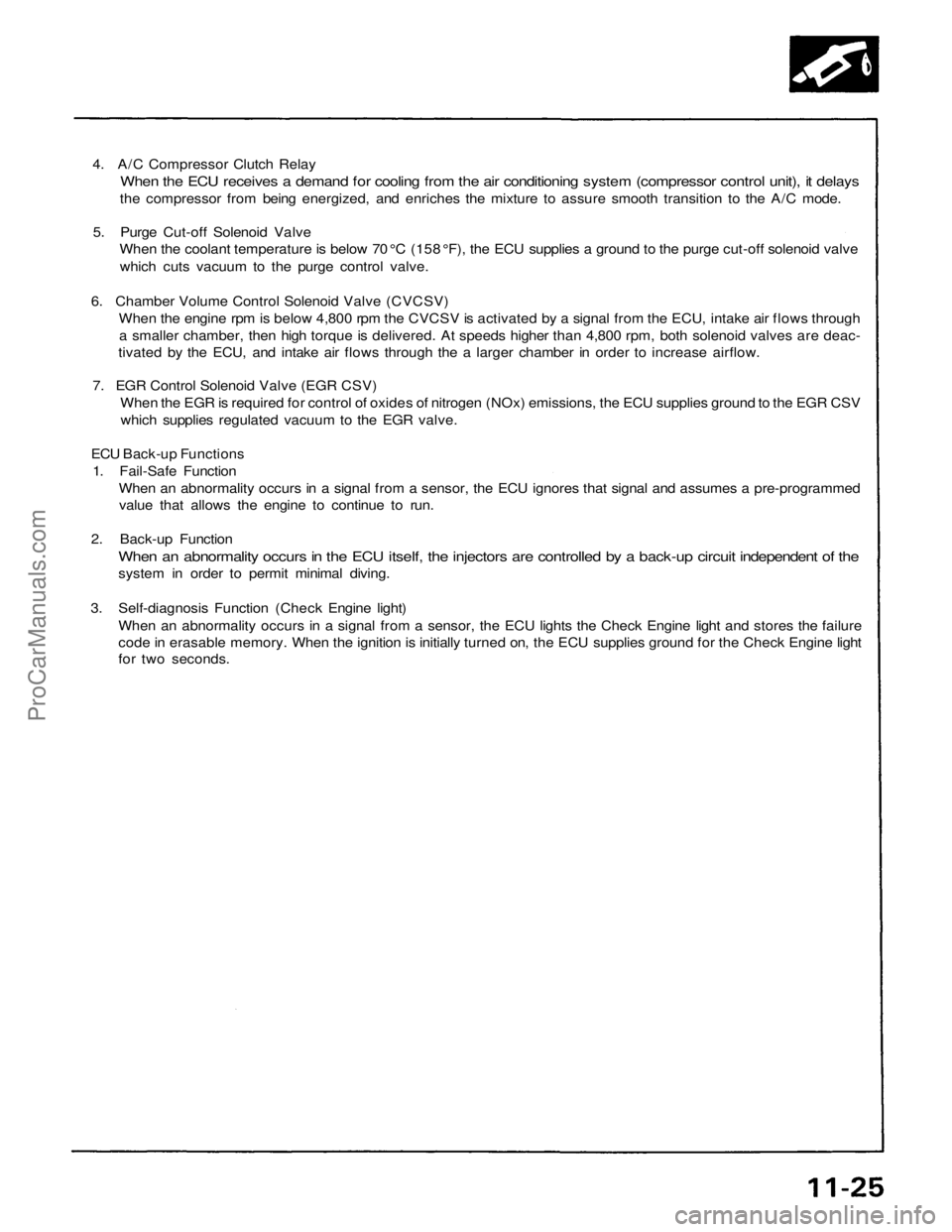
4. A/C Compressor Clutch Relay
When the ECU receives a demand for cooling from the air conditioning system (compressor control unit), it delays
the compressor from being energized, and enriches the mixture to assure smooth transition to the A/C mode.
5. Purge Cut-off Solenoid Valve
When the coolant temperature is below 70 °C (158 °F), the ECU supplies a ground to the purge cut-off solenoid valve
which cuts vacuum to the purge control valve.
6. Chamber Volume Control Solenoid Valve (CVCSV)
When the engine rpm is below 4,800 rpm the CVCSV is activated by a signal from the ECU, intake air flows through
a smaller chamber, then high torque is delivered. At speeds higher than 4,800 rpm, both solenoid valves are deac-
tivated by the ECU, and intake air flows through the a larger chamber in order to increase airflow.
7. EGR Control Solenoid Valve (EGR CSV)
When the EGR is required for control of oxides of nitrogen (NOx) emissions, the ECU supplies ground to the EGR CSV
which supplies regulated vacuum to the EGR valve.
ECU Back-up Functions
1. Fail-Safe Function
When an abnormality occurs in a signal from a sensor, the ECU ignores that signal and assumes a pre-programmed
value that allows the engine to continue to run.
2. Back-up Function
When an abnormality occurs in the ECU itself, the injectors are controlled by a back-up circuit independent of the
system in order to permit minimal diving.
3. Self-diagnosis Function (Check Engine light)
When an abnormality occurs in a signal from a sensor, the ECU lights the Check Engine light and stores the failure
code in erasable memory. When the ignition is initially turned on, the ECU supplies ground for the Check Engine light
for two seconds.ProCarManuals.com
Page 1484 of 1640
System Description
The idle speed of the engine is controlled by the Electronic Air Control Valve (EACV).
The valve changes the amount of air bypassing into the intake manifold in response to electric current sent from the ECU.
When the EACV is activated, the valve opens to maintain the proper idle speed.
BLU/REDEACV
ECU
YEL/BLK
TO MAIN
RELAY
IDLE
ADJUSTING
SCREW
FAST
IDLE
VALVE
(cont'd)
ProCarManuals.com
Page 1487 of 1640

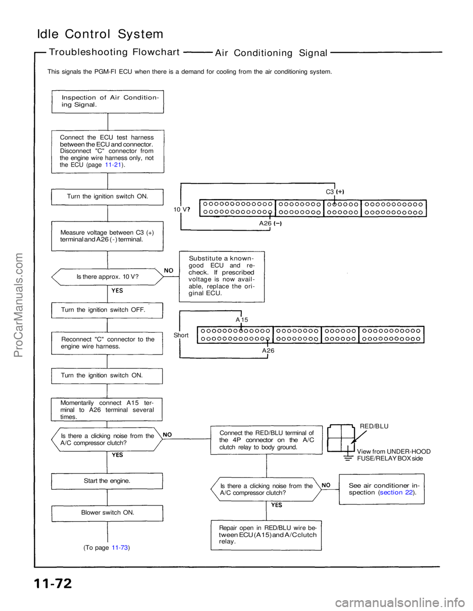
Idle Control System
Troubleshooting Flowchart
Air Conditioning Signal
This signals the PGM-FI ECU when there is a demand for cooling from the air conditioning system.
Inspection of Air Condition-
ing Signal.
Connect the ECU test harness
between the ECU and connector.
Disconnect "C" connector from
the engine wire harness only, not
the ECU (page 11-21).
Turn the ignition switch ON.
Measure voltage between C3 (+)
terminal and A26 (-) terminal.
Is there approx. 10 V?
Substitute a known-
good ECU and re-
check. If prescribed
voltage is now avail- able, replace the ori-
ginal ECU.
C3
A26
10 V
Turn the ignition switch OFF. Reconnect "C" connector to the
engine wire harness.
Turn the ignition switch ON.
Momentarily connect A15 ter-
minal to A26 terminal several
times.
Is there a clicking noise from the
A/C compressor clutch? Connect the RED/BLU terminal of
the 4P connector on the A/C
clutch relay to body ground. RED/BLU
A 15
Short
A26
View from UNDER-HOODFUSE/RELAY BOX side
Start the engine.
Is there a clicking noise from the
A/C compressor clutch?
See air conditioner in-
spection (section 22).
Repair open in RED/BLU wire be-
tween ECU (A15) and A/C clutch
relay.
Blower switch ON.
(To page 11-73)ProCarManuals.com
Page 1499 of 1640
6. Turn the ignition switch OFF.
7. Reconnect the 2P connector on the EACV, then
remove CLOCK fuse in the under-hood fuse/relay
box for 10 seconds to reset ECU.
8. Restart and idle the engine with no-load conditions
in which the headlights, blower fan, rear defogger,
cooling fan, and air conditioner are not operating
for one minute, then check the idle speed.
Idle speed should be:ProCarManuals.com
Page 1501 of 1640

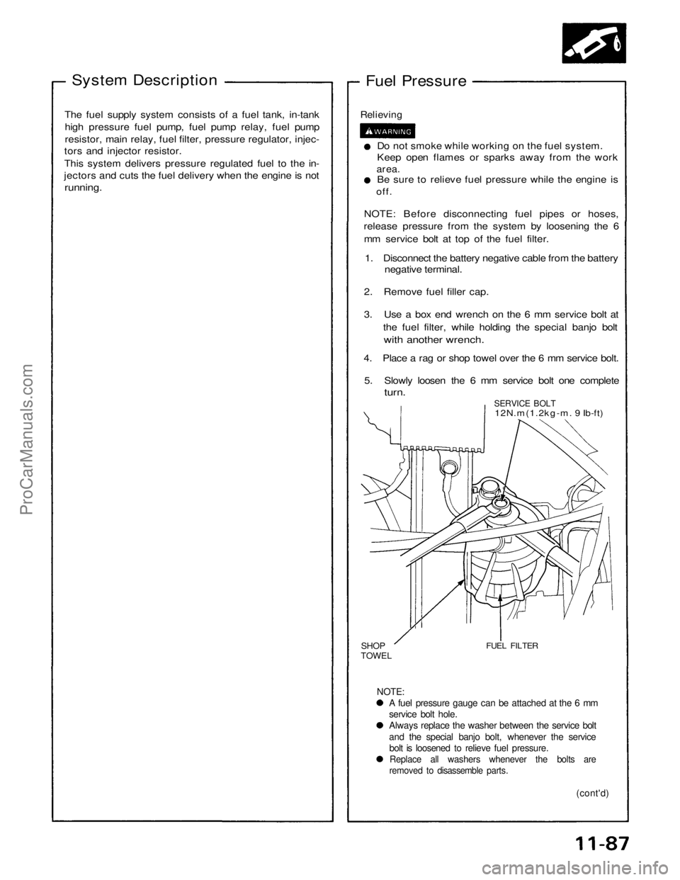
System Description
Fuel Pressure
The fuel supply system consists of a fuel tank, in-tank high pressure fuel pump, fuel pump relay, fuel pump
resistor, main relay, fuel filter, pressure regulator, injec-
tors and injector resistor.
This system delivers pressure regulated fuel to the in-
jectors and cuts the fuel delivery when the engine is not
running.
Relieving
Do not smoke while working on the fuel system.
Keep open flames or sparks away from the work
area.
Be sure to relieve fuel pressure while the engine is
off.
NOTE: Before disconnecting fuel pipes or hoses,
release pressure from the system by loosening the 6
mm service bolt at top of the fuel filter.
1. Disconnect the battery negative cable from the battery negative terminal.
2. Remove fuel filler cap.
3. Use a box end wrench on the 6 mm service bolt at the fuel filter, while holding the special banjo bolt
with another wrench.
4. Place a rag or shop towel over the 6 mm service bolt.
5. Slowly loosen the 6 mm service bolt one complete
turn.
SERVICE BOLT
12N.m(1.2kg-m. 9 Ib-ft)
SHOP
TOWEL
FUEL FILTER
NOTE:
A fuel pressure gauge can be attached at the 6 mm
service bolt hole.
Always replace the washer between the service bolt
and the special banjo bolt, whenever the service
bolt is loosened to relieve fuel pressure.
Replace all washers whenever the bolts are
removed to disassemble parts.
(cont'd)
ProCarManuals.com