1991 ACURA NSX relay
[x] Cancel search: relayPage 1209 of 1640
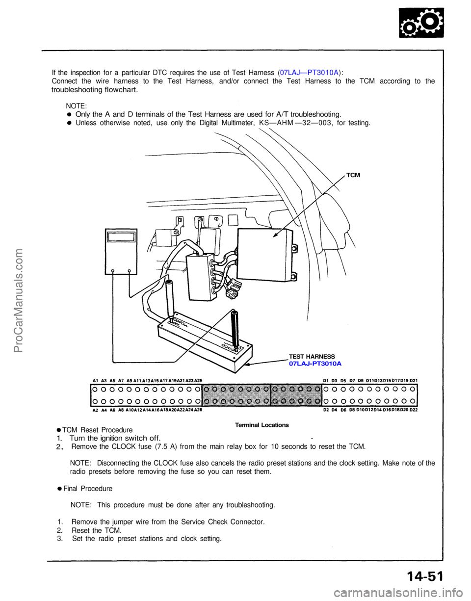
If the inspection for a particular DTC requires the use of Test Harness (07LAJ—PT3010A):
Connect the wire harness to the Test Harness, and/or connect the Test Harness to the TCM according to the
troubleshooting flowchart.
TCM
TEST HARNESS
Terminal Locations
TCM Reset Procedure
Turn the ignition switch off. -
, Remove the CLOCK fuse (7.5 A) from the main relay box for 10 seconds to reset the TCM.
1
2
NOTE: Disconnecting the CLOCK fuse also cancels the radio preset stations and the clock setting. Make note of the
radio presets before removing the fuse so you can reset them.
Final Procedure NOTE: This procedure must be done after any troubleshooting.
1. Remove the jumper wire from the Service Check Connector.
2. Reset the TCM. 3. Set the radio preset stations and clock setting.
Only the A and D terminals of the Test Harness are used for A/T troubleshooting.
Unless otherwise noted, use only the Digital Multimeter, KS—AHM —32—003, for testing.
07LAJ-PT3010A
NOTE:ProCarManuals.com
Page 1211 of 1640
If a customer describes the symptoms for codes 3, 6, 11, 14 or 1 5 yet the indicator light is not blinking, it will
be necessary to recreate the symptom by test driving, and then checking the indicator light with the ignition
still
ON.
If the indicator light displays codes 1,2,3,8, 11, or 16, check first the No. 9, 13 and 18 and fuse before elec-
trical troubleshooting.
If any of the fuses have blown, repair them and then recheck. If the indicator light displays codes other than those listed above or stays lit continuously, the TCM is faulty.
Sometimes the indicator light and the Malfunction Indicator Lamp (MID/Check Engine light may come on
simultaneously. If so, check the PGM-FI system according to the number of blinks on the MIL/Check Engine light,
then reset the memory by removing the CLOCK fuse in the main relay box for more than 10 seconds. Drive the vehicle for several minutes at speed over 30 mph (50 km/h), then recheck the MIL/Check Engine light.PGM-FI system
The PGM-FI system on this model is a sequential multiport fuel injectin system.
The indicator light may comes on, indicating a system problem, when, in fact, there is a poor or intermittent
electrical connection. First, check the electrical connections, clean or repair connections if necessary.If the electrical readings are not as specified when using the test harness, check the test harness connections
before proceeding.
Disconnecting the CLOCK fuse also cancels the radio preset stations and the clock setting. Make note of the radio
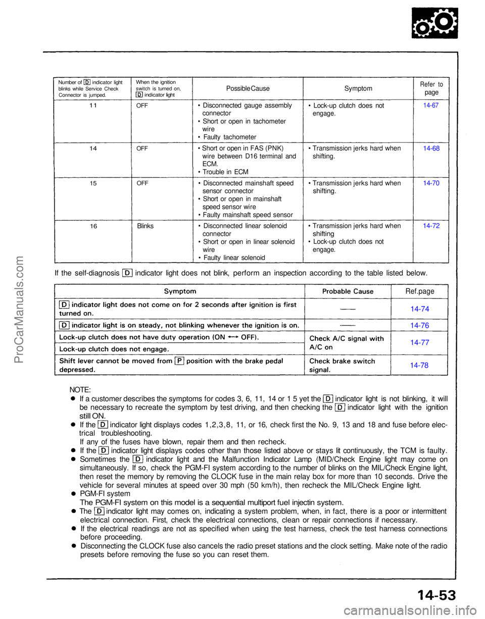
presets before removing the fuse so you can reset them. If the self-diagnosis indicator light does not blink, perform an inspection according to the table listed below.
Symptom
• Lock-up clutch does not
engage.
• Transmission jerks hard when shifting.
• Transmission jerks hard when
shifting.
• Transmission jerks hard when
shifting
• Lock-up clutch does not
engage.
14-7214-70 14-68
14-67
Refer to
page
Possible Cause
• Disconnected gauge assembly connector
• Short or open in tachometer wire
• Faulty tachometer
• Short or open in FAS (PNK) wire between D16 terminal and
ECM.
• Trouble in ECM
• Disconnected mainshaft speed sensor connector
• Short or open in mainshaft speed sensor wire
• Faulty mainshaft speed sensor
• Disconnected linear solenoid connector
• Short or open in linear solenoid wire
• Faulty linear solenoid
Blinks
OFF
OFF
OFF
When the ignition
switch is turned on,
indicator light
Number of indicator light
blinks while Service CheckConnector is jumped.
11
14
15
16
Ref.page
14-74
14-76
14-77
14-78
NOTE:ProCarManuals.com
Page 1325 of 1640
FUSE BOX
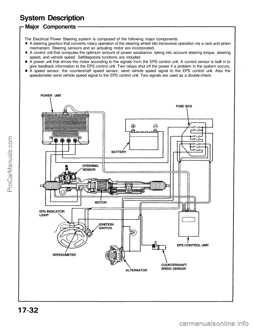
System Description
Major Components
The Electrical Power Steering system is composed of the following major components:
EPS CONTROL UNIT
COUNTERSHAFT
SPEED SENSOR
ALTERNATOR
SPEEDOMETER
EPS INDICATOR
LIGHT
STEERING
SENSOR
BATTERY
POWER UNIT
MOTOR
IGNITION
SWITCH
A steering gearbox that converts rotary operation of the steering wheel into transverse operation via a rack and pinion
mechanism. Steering sensors and an actuating motor are incorporated.
A control unit that computes the optimum amount of power assistance, taking into account steering torque, steering
speed, and vehicle speed. Selfdiagnosis functions are included.
A power unit that drives the motor according to the signals from the EPS control unit. A current sensor is built in to
give feedback information to the EPS control unit. Two relays shut off the power if a problem in the system occurs.
A speed sensor, the countershaft speed sensor, send vehicle speed signal to the EPS control unit. Also the
speedometer send vehicle speed signal to the EPS control unit. Two signals are used as a double-check.ProCarManuals.com
Page 1330 of 1640
Self-Diagnosis Function
The EPS control unit monitors the system inputs and outputs, and the driving current of the motor. If there is a problem
in the system, the control unit turns the system off by actuating the relay in the power unit. Power assist stops and
normal manual steering operation resumes. The control unit also turns the EPS indicator light on to alert the driver, and
memorizes the problem in the form of a code. Connecting the terminals of the service check connector with a jumper
wire enables the EPS indicator light to blink the problem code when the ignition switch is turned on.
Unloader Control
If the steering wheel is turned fully and held in the full-lock position, the steering torque reaches the maximum point,
and an over-current flows to the motor and the power unit. The control unit detects this and reduces the current flow
to the motor.
Average Moving Current Control
The electric current flow to the motor is estimated from the current values detected by the current sensor, and the aver-
age current is obtained at two second intervals. The motor driving current is suppressed when the average current value
exceeds a predetermined marginal value. The control unit regurates the motor current during continuous loading to sup-
press any excessive temperature rise in the power unit and the motor.
Over-Voltage Control
If there is an excessive increase in power source voltage due to a poor battery condition, an alternator voltage regulator
problem, etc., the motor assisting force increases, resulting in excessive control. To prevent this, the control unit signals
to the power unit are corrected to ensure that adequate assisting force is generated.ProCarManuals.com
Page 1331 of 1640
System Description
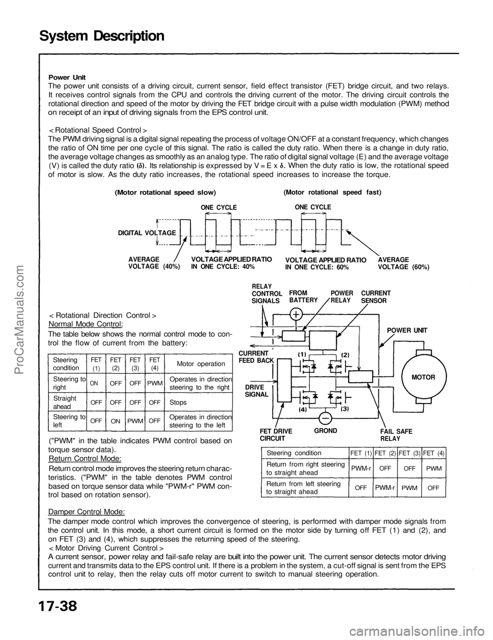
Power Unit
The power unit consists of a driving circuit, current sensor, field effect transistor (FET) bridge circuit, and two relays.
It receives control signals from the CPU and controls the driving current of the motor. The driving circuit controls the
rotational direction and speed of the motor by driving the FET bridge circuit with a pulse width modulation (PWM) method
on receipt of an input of driving signals from the EPS control unit.
< Rotational Speed Control >
The PWM driving signal is a digital signal repeating the process of voltage ON/OFF at a constant frequency, which changes the ratio of ON time per one cycle of this signal. The ratio is called the duty ratio. When there is a change in duty ratio,
the average voltage changes as smoothly as an analog type. The ratio of digital signal voltage (E) and the average voltage
(Motor rotational speed fast)
ONE CYCLE
AVERAGE
VOLTAGE (60%)
VOLTAGE APPLIED RATIO
IN ONE CYCLE: 60%
CURRENT
SENSOR
POWER
RELAY
FROM
BATTERY
RELAY
CONTROL
SIGNALS
VOLTAGE APPLIED RATIO
IN ONE CYCLE: 40%
AVERAGE
VOLTAGE (40%)
(Motor rotational speed slow)
DIGITAL VOLTAGE
ONE CYCLE
CURRENT
FEED BACK
DRIVE
SIGNAL
< Rotational Direction Control >
Normal Mode Control:
The table below shows the normal control mode to con-
trol the flow of current from the battery:
("PWM" in the table indicates PWM control based on
torque sensor data). Return Control Mode:
Return control mode improves the steering return charac-
teristics. ("PWM" in the table denotes PWM control based on torque sensor data while "PWM-r" PWM con-
trol based on rotation sensor).
POWER UNIT
FET DRIVE
CIRCUIT
GROND
FAIL SAFE
RELAY
Damper Control Mode:
The damper mode control which improves the convergence of steering, is performed with damper mode signals from
the control unit. In this mode, a short current circuit is formed on the motor side by turning off FET (1) and (2), and on FET (3) and (4), which suppresses the returning speed of the steering. < Motor Driving Current Control >
A current sensor, power relay and fail-safe relay are built into the power unit. The current sensor detects motor driving
current and transmits data to the EPS control unit. If there is a problem in the system, a cut-off signal is sent from the EPS
control unit to relay, then the relay cuts off motor current to switch to manual steering operation. (V) is called the duty ratio
of motor is slow. As the duty ratio increases, the rotational speed increases to increase the torque. When the duty ratio is low, the rotational speed
Its relationship is expressed by V = E x
Steering
condition Steering to
rightStraight
ahead
Steering to
left
OFFOFF
ON
FET
(1)
FET
(2)
FET
(3)
FET
(4)
OFF
OFF
OFF
ON
OFF
PWM
OFF
OFF
PWM
Motor operation
Stops
Operates in direction
steering to the left Operates in direction
steering to the right
Steering condition
Return from right steering
to straight ahead
Return from left steering
to straight ahead
FET (1)
PWM-r
OFF
FET (2)
OFF
PWM-r
FET (3)
OFF
PWM
OFF
PWM
FET (4)
MOTORProCarManuals.com
Page 1332 of 1640
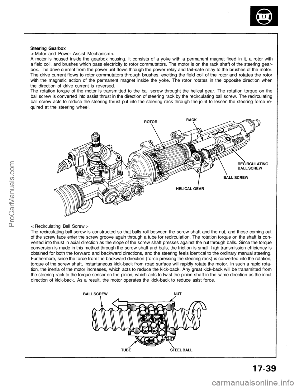
Steering Gearbox
< Motor and Power Assist Mechanism >
A motor is housed inside the gearbox housing. It consists of a yoke with a permanent magnet fixed in it, a rotor with
a field coil, and brushes which pass electricity to rotor commutators. The motor is on the rack shaft of the steering gear-
box. The drive current from the power unit flows through the power relay and fail-safe relay to the brushes of the motor.
The drive current flows to rotor commutators through brushes, exciting the field coil of the rotor and rotates the rotor
with the magnetic action of the permanent magnet inside the yoke. The rotor rotates in the opposite direction when
the direction of drive current is reversed.
The rotation torque of the motor is transmitted to the ball screw throught the helical gear. The rotation torque on the
ball screw is converted into assist thrust in the direction of steering rack by the recirculating ball screw. The recirculating
ball screw acts to reduce the steering thrust put into the steering rack through the joint to lessen the steering force re-
quired at the steering wheel.
< Recirculating Ball Screw >
The recirculating ball screw is constructed so that balls roll between the screw shaft and the nut, and those coming out
of the screw face enter the screw groove again through a tube for recirculation. The rotation torque on the shaft is con-
verted into thrust in axial direction as the slope of the screw shaft presses against the nut through balls. Since the torque
conversion is made in this method through the screw shaft and balls, the friction is small, high transmission efficiency is
obtained for both the forward and backward directions, and the steering feels identical to the ordinary manual steering.
Furthermore, since the force from the backward direction (force pressing the steering rack) is converted into the rotation,
torque of the screw shaft, instantaneous kick-back from road surface will rapidly rotate the motor. In such a rapid rota-
tion, the inertia of the motor increases, which acts to reduce the kick-back. Any great kick-back will be transmitted from
the steering rack to the torque sensor on the pinion, which acts to twist the pinion shaft in the same direction as the input
direction of kick-back. As a result, the motor operates the kick-back to reduce asist force.
BALL SCREW
ROTOR
NUT
TUBE
STEEL BALL
HELICAL GEAR
BALL SCREW
RECIRCULATING
BALL SCREW
RACKProCarManuals.com
Page 1333 of 1640
Wiring Locations
EPS CONTROL UNIT
MAIN RELAY BOX
POWER UNIT
TORQUE SENSOR 6-P CONNECTOR/
STEERING WHEEL SPEED SENSOR
4-P CONNECTOR
STEERING GEARBOX
(TORQUE SENSOR/STEERING WHEEL
SPEED SENSOR)
UNDER-DASH FUSE/RELAY BOX
TRANSMISSION CONTROL MODULE (TCM)
22-P CONNECTOR
VEHICLE SPEED SENSOR
(VSS)
ALTERNATOR 4-P CONNECTOR
EPS INDICATOR LIGHTProCarManuals.com
Page 1336 of 1640
Troubleshooting
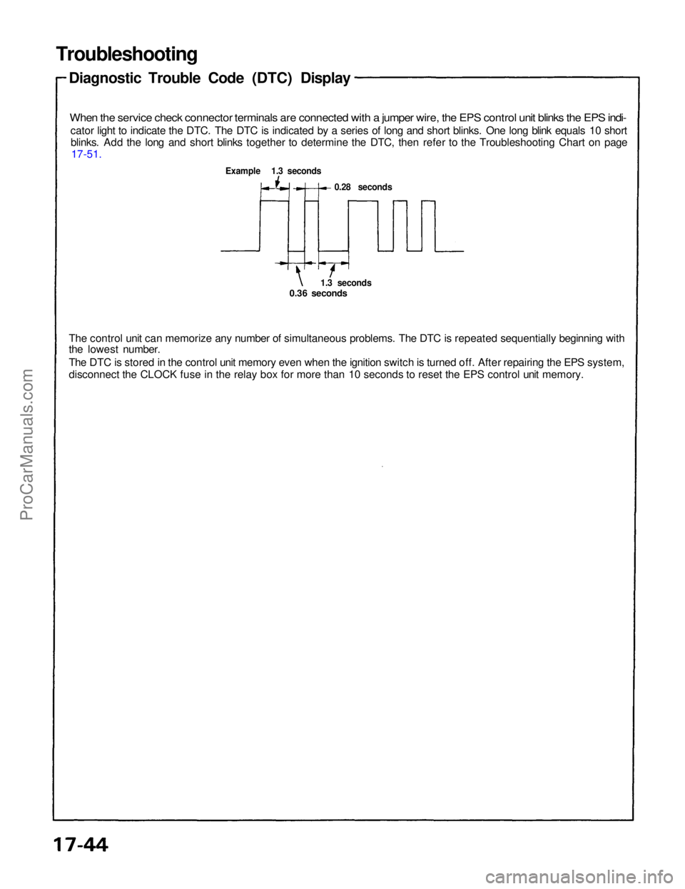
Diagnostic Trouble Code (DTC) Display
When the service check connector terminals are connected with a jumper wire, the EPS control unit blinks the EPS indi-
cator light to indicate the DTC. The DTC is indicated by a series of long and short blinks. One long blink equals 10 shortblinks. Add the long and short blinks together to determine the DTC, then refer to the Troubleshooting Chart on page 17-51.
Example 1.3 seconds
0.28 seconds
1.3 seconds
0.36 seconds
The control unit can memorize any number of simultaneous problems. The DTC is repeated sequentially beginning with
the lowest number.
The DTC is stored in the control unit memory even when the ignition switch is turned off. After repairing the EPS system,
disconnect the CLOCK fuse in the relay box for more than 10 seconds to reset the EPS control unit memory.ProCarManuals.com