Page 1361 of 1640
Component Location Index
INDICATOR LIGHT
ACTIVATION LIGHT INDICATOR LIGHT
UNDER-HOOD
FUSE/RELAY BOX
ABS
CONTROL UNIT
STEERING
ANGLE SENSOR
(page 19-138)
TCS SWITCH(page 19-137)
UNDER-DASH FUSE BOX
A/T GEAR POSITION
SWITCH
FAIL-SAFE RELAY
(page 19-137)
ENGINE
COMPARTMENT
FUSE/RELAY BOX
TRANSMISSON
CONTROL
MODULE (TCM)
ENGINE
GROUND
TCS CONTROL
UNIT
ENGINE CONTROL
MODULE (ECM)
ACCELERATOR
PEDAL
ANGLE
SENSOR
THROTTLE
ACTUATOR
THROTTLE
POSITION (TP)
SENSORProCarManuals.com
Page 1366 of 1640

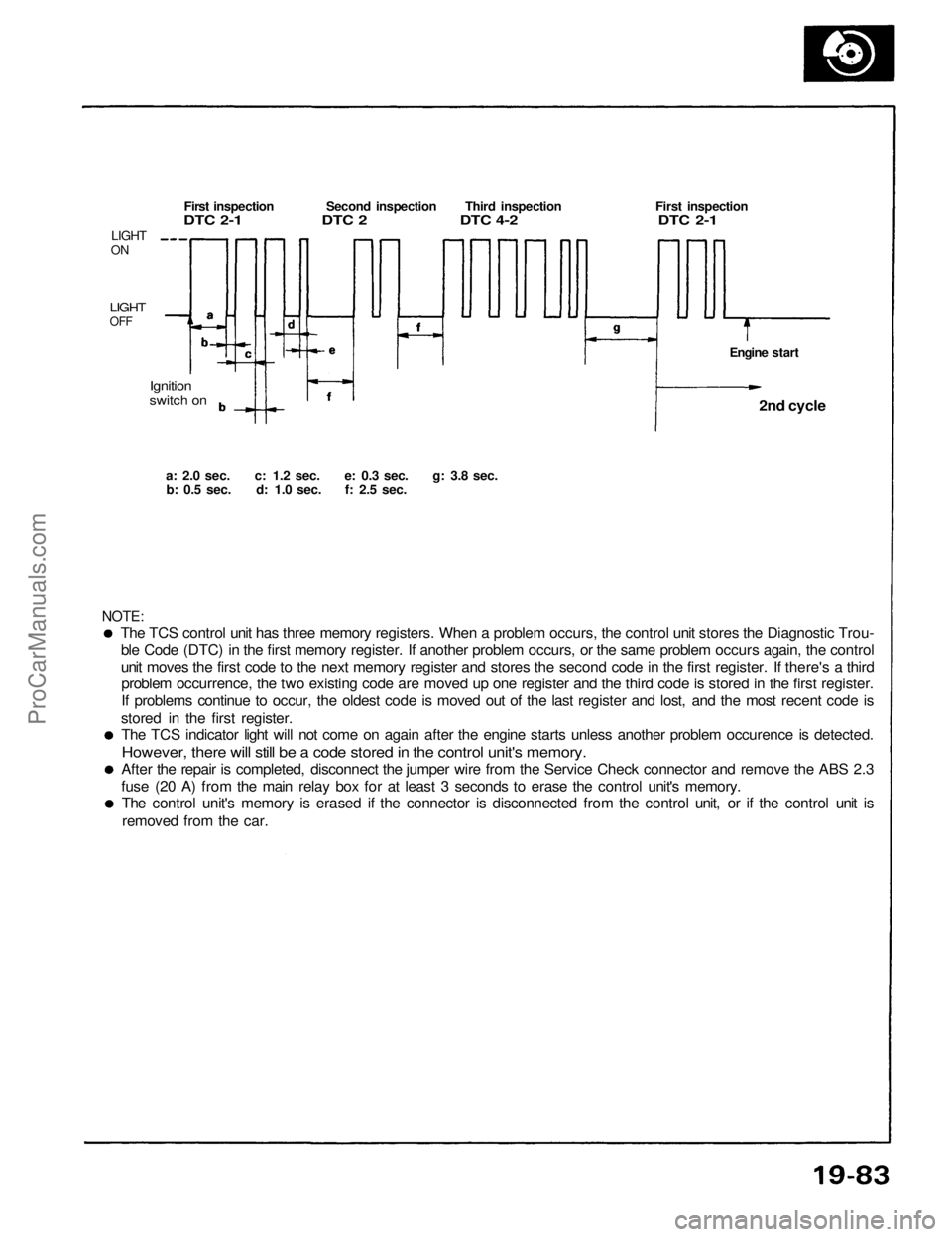
The TCS control unit has three memory registers. When a problem occurs, the control unit stores the Diagnostic Trou-
ble Code (DTC) in the first memory register. If another problem occurs, or the same problem occurs again, the control
unit moves the first code to the next memory register and stores the second code in the first register. If there's a thirdproblem occurrence, the two existing code are moved up one register and the third code is stored in the first register.
If problems continue to occur, the oldest code is moved out of the last register and lost, and the most recent code is
stored in the first register. The TCS indicator light will not come on again after the engine starts unless another problem occurence is detected.
However, there will still be a code stored in the control unit's memory.
After the repair is completed, disconnect the jumper wire from the Service Check connector and remove the ABS 2.3
fuse (20 A) from the main relay box for at least 3 seconds to erase the control unit's memory. The control unit's memory is erased if the connector is disconnected from the control unit, or if the control unit is
removed from the car.
NOTE:
a: 2.0
sec.
c: 1.2
sec.
e: 0.3
sec.
g: 3.8
sec.
b: 0.5
sec.
d: 1.0
sec.
f: 2.5
sec.
Ignition
switch on
LIGHT
ON
LIGHT
OFF
First inspection Second inspection Third inspection First inspection
DTC 2-1 DTC 2 DTC 4-2 DTC 2-1
Engine start2nd cycle
ProCarManuals.com
Page 1368 of 1640
There should be continuity between the A and B termi-
nals when the battery is connected to the C and D ter-
minals.
There should be no continuity between the A and B ter-
minals when the battery is disconnected.
Fail-Safe Relay Test
Electronic Components
TCS Switch Test
There should be continuity between the D and E termi-
nals when the switch is pushed and there should be no
continuity when the switch is relesed.
Indicator light
Switch
LightProCarManuals.com
Page 1384 of 1640
Relay and Control Unit Locations
Dashboard
CLIMATE CONTROL UNIT
TURN SIGNAL/HAZARD
RELAY
UNDER-DASH FUSE BOX
INTEGRATED
CONTROL UNIT
DASHBOARD
LOWER COVER
STARTER CUT RELAY
Wire colors: BLK/WHT
BLK/WHT, BLU/GRN,
and BLK/BLUProCarManuals.com
Page 1385 of 1640
Dashboard, Door and Floor
DRIVER'S DOOR PANEL
POWER WINDOW
CONTROL UNIT
CIGARETTE LIGHTER
RELAY
SRS UNIT
FOOT WELL BASS SPEAKER RIGHT FRONT FLOOR
PANEL
EPS POWER UNIT
(Behind foot well
bass speaker)
SECURITY CONTROL UNIT
DAYTIME RUNNING
LIGHTS CONTROL
UNIT (Canada)
ABS CONTROL UNIT
CRUISE CONTROL UNIT
EPS CONTROL UNIT
(A/T)
POWER DOOR LOCK
CONTROL UNIT
Wire colors: YEL/RED, BLU/GRN, BRN/YEL, and BLKProCarManuals.com
Page 1386 of 1640
Relay and Control Unit Locations
Rear Bulkhead
FAN CONTROL
UNIT
ECM
TCS FAIL-SAFE
RELAY
Wire colors: YEL,
and LT GRN/BLK TRANSMISSION CONTROL
MODULE (TCM)
DASH LIGHTS
BRIGHTNESS
CONTROL UNIT
TCS CONTROL UNIT
GRN/RED, RED/BLK,ProCarManuals.com
Page 1387 of 1640
RETRACTABLE HEADLIGHT
CONTROL UNIT
INTERLOCK CONTROL
UNIT (A/T)
FUEL PUMP RELAY
Wire colors: YEL, RED,
BLK/YEL, and BLK/REDProCarManuals.com
Page 1388 of 1640
Relay and Control Unit Locations
Engine Compartment
REAR WINDOW DEFOGGER
RELAY
ENGINE COMPARTMENT
FUSE/RELAY BOX
ENGINE COMPARTMENT
FAN RELAY
Wire colors: YEL/BLU,
BLK/YEL, WHT/RED,
and WHT/BLU
IGNITION CONTROL
MODULE (ICM)ProCarManuals.com