Page 1117 of 1640
Fuel Pump
Description
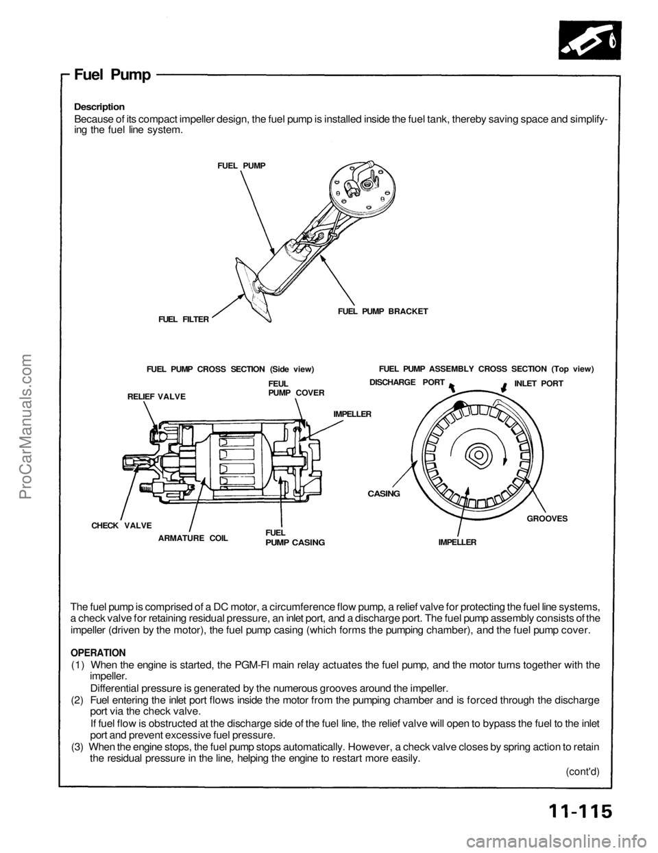
Because of its compact impeller design, the fuel pump is installed inside the fuel tank, thereby saving space and simplify-
ing the fuel line system.
FUEL PUMP
FUEL PUMP BRACKET
FUEL FILTER
FUEL PUMP CROSS SECTION (Side view)
RELIEF VALVE
FEUL
PUMP COVER
FUEL PUMP ASSEMBLY CROSS SECTION (Top view)
DISCHARGE PORT
INLET PORT
IMPELLER
CHECK VALVE
ARMATURE COIL
FUEL
PUMP CASING
IMPELLER
GROOVES
CASING
The fuel pump is comprised of a DC motor, a circumference flow pump, a relief valve for protecting the fuel line systems,
a check valve for retaining residual pressure, an inlet port, and a discharge port. The fuel pump assembly consists of the
impeller (driven by the motor), the fuel pump casing (which forms the pumping chamber), and the fuel pump cover.
OPERATION
(1) When the engine is started, the PGM-FI main relay actuates the fuel pump, and the motor turns together with the
impeller.
Differential pressure is generated by the numerous grooves around the impeller.
(2) Fuel entering the inlet port flows inside the motor from the pumping chamber and is forced through the discharge
port via the check valve.
If fuel flow is obstructed at the discharge side of the fuel line, the relief valve will open to bypass the fuel to the inlet
port and prevent excessive fuel pressure.
(3) When the engine stops, the fuel pump stops automatically. However, a check valve closes by spring action to retain
the residual pressure in the line, helping the engine to restart more easily.
(cont'd)ProCarManuals.com
Page 1118 of 1640
Testing
Do not smoke during the test. Keep open
If you suspect a problem with the fuel pump, check that
the fuel pump actually runs; When it is ON, you will hear some noise if you hold your ear to the fuel fill port with
the fuel fill cap removed. The fuel pump should run for
two seconds when the ignition switch is first turned on. If the fuel pump does not make noise, check as follows:
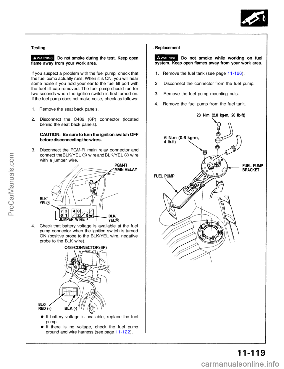
1. Remove the seat back panels.
2. Disconnect the C489 (6P) connector (located behind the seat back panels).
CAUTION: Be sure to turn the ignition switch OFF
before disconnecting the wires.
3. Disconnect the PGM-FI main relay connector and connect the BLK/YEL wire and BLK/YEL wire
with a jumper wire.
1. Remove the fuel tank (see page 11-126).
2. Disconnect the connector from the fuel pump.
3. Remove the fuel pump mounting nuts.
4. Remove the fuel pump from the fuel tank.
If battery voltage is available, replace the fuel
pump.
If there is no voltage, check the fuel pump
ground and wire harness (see page 11-122).
4. Check that battery voltage is available at the fuel
pump connector when the ignition switch is turned
ON (positive probe to the BLK/YEL wire, negative
probe to the BLK wire).
C489 CONNECTOR (6P)
BLK/
RED (+)
BLK (-)
JUMPER WIRE
flame away from your work area.
Replacement
Do not smoke while working on fuel
system. Keep open flames away from your work area.
28 N.
m (2.8 kg-m, 20 Ib-ft)
6 N.m
(0.6 kg-m,
4 Ib-ft)
FUEL PUMP
BRACKET
FUEL PUMP
PGM-FI
MAIN RELAY
BLK/
YEL
BLK/
YELProCarManuals.com
Page 1119 of 1640
Fuel Supply System
Description
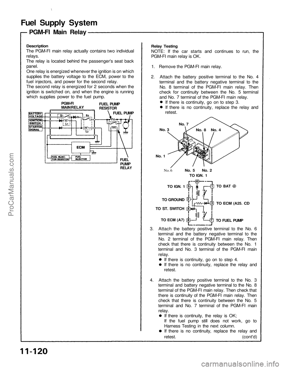
The PGM-FI main relay actually contains two individual
relays.
The relay is located behind the passenger's seat backpanel.
One relay is energized whenever the ignition is on which
supplies the battery voltage to the ECM, power to the
fuel injectors, and power for the second relay.
The second relay is energized for 2 seconds when theignition is switched on, and when the engine is running
which supplies power to the fuel pump.
Relay Testing
NOTE: If the car starts and continues to run, the
PGM-FI main relay is OK.
1. Remove the PGM-FI main relay.
2. Attach the battery positive terminal to the No. 4 terminal and the battery negative terminal to theNo. 8 terminal of the PGM-FI main relay. Then
check for continuity between the No. 5 terminal
and No. 7 terminal of the PGM-FI main relay.
3. Attach the battery positive terminal to the No. 6 terminal and the battery negative terminal to theNo. 2 terminal of the PGM-FI main relay. Then
check that there is continuity between the No. 1
terminal and No. 3 terminal of the PGM-FI main
relay.
FUEL
PUMP
RELAY
FUEL PUMP
RESISTOR
FUEL PUMP
PGM-FI
MAIN RELAY
No. 3
No. 7
No. 8 No. 4
No. 1
No. 6
No. 5 No. 2
TO
IGN.
1
TO BAT
TO
IGN.
1
TO GROUND
TO ST. SWITCH
TO ECM
(A7)
TO ECM
(A25.
CD
TO FUEL PUMP
PGM-FI Main Relay
If there is continuity, go on to step 4.
If there is no continuity, replace the relay and
retest.
4. Attach the battery positive terminal to the No. 3 terminal and battery negative terminal to the No. 8
terminal of the PGM-FI main relay. Then check that
there is continuity of the PGM-FI main relay. Then
check that there is continuity between the No. 5
terminal and No. 7 terminal of the PGM-FI main relay. If there is continuity, the relay is OK;
If the fuel pump still does not work, go to
Harness Testing in the next column. If there is no continuity, replace the relay and
retest. (cont'd) If there is continuity, go on to step 3.
If there is no continuity, replace the relay and
retest.ProCarManuals.com
Page 1120 of 1640
Fuel Supply System
PGM-FI Main Relay (cont'd)
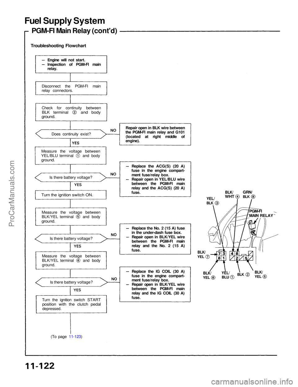
Troubleshooting Flowchart
(To page 11-123)
BLK/
WHT
GRN/
YEL/
BLK
PGM-FI
MAIN RELAY
BLK/
YEL
BLK
YEL/
BLU
BLK/
YEL
BLK/
YEL
BLK
Engine will not start.
Inspection of PGM-FI main
relay.
Disconnect the PGM-FI main
relay connectors.
Check for continuity between
BLK terminal and body
ground.
Does continuity exist?
Measure the voltage between YEL/BLU terminal and body
ground.
Is there battery voltage?
Turn the ignition switch ON.
Measure the voltage between BLK/YEL terminal and body
ground.
Is there battery voltage?
Measure the voltage between BLK/YEL terminal and body
ground.
Is there battery voltage?
Turn the ignition switch START
position with the clutch pedal
depressed.
Repair open in BLK wire between
the PGM-FI main relay and G101
(located at right middle of
engine).
Replace the ACG(S) (20 A)
fuse in the engine compart-
ment fuse/relay box.
Repair open in YEL/BLU wire
between the PGM-FI main
relay and the ACG(S) (20 A)
fuse.
Replace the No. 2 (15 A) fuse
in the under-dash fuse box.
Repair open in BLK/YEL wire
between the PGM-FI main
relay and the No. 2 (15 A)
fuse.
Replace the IG COIL (30 A)
fuse in the engine compart- ment fuse/relay box.
Repair open in BLK/YEL wire
between the PGM-FI main
relay and the IG COIL (30 A)
fuse.ProCarManuals.com
Page 1121 of 1640
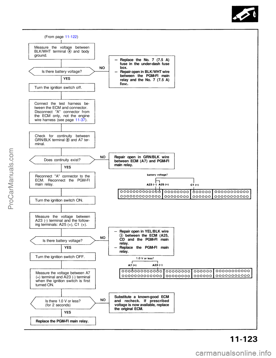
(From page 11-122)
Connect the test harness be-
tween the ECM and connector.
Disconnect "A" connector from
the ECM only, not the engine
wire harness (see page 11-37).
Measure the voltage between BLK/WHT terminal and body
ground.
Is there battery voltage?
Check for continuity between GRN/BLK terminal and A7 ter-
minal.
Does continuity exist?
Reconnect "A" connector to the
ECM. Reconnect the PGM-FI
main relay.
Turn the ignition switch ON.
Measure the voltage between
A23 (-) terminal and the follow-
ing terminals: A25 (+), C1 (+).
Is there battery voltage?
Turn the ignition switch OFF.
Measure the voltage between A7
(+) terminal and A23 (-) terminal
when the ignition switch is first
turned ON.
Is there 1.0 V or less?
(for 2 seconds)
Replace the PGM-FI main relay. Replace the No. 7 (7.5 A)
fuse in the under-dash fuse
box.
Repair open in BLK/WHT wire
between the PGM-FI main
relay and the No. 7 (7.5 A)
fuse.
Repair open in GRN/BLK wire
between ECM (A7) and PGM-FI
main relay. Repair open in YEL/BLK wire between the ECM (A25,
CD and the PGM-FI main
relay.
Replace the PGM-FI main
relay.
Substitute a known-good ECM
and recheck. If prescribed voltage is now available, replace
the original ECM.
Turn the ignition switch off.ProCarManuals.com
Page 1122 of 1640
Fuel Supply System
Fuel Pump Resistor
Troubleshooting Flowchart
(To page 11-125) FUEL PUMP
RESISTOR
Inspect the PGM-FI main relay
(seepage 11-120).
Engine will not start.
Inspection of fuel pump
resistor.
Disconnect the fuel pump resis-
tor connector.
Measure the voltage between
BLK/YEL (+) (on harness side)
and body ground (-) when the ig-
nition switch is first turned ON.
Is there battery voltage?
(for 2 seconds)
Turn the ignition switch OFF.
Install a jumper wire between
two terminals on the wire harness side of fuel pump
resistor.
Turn the ignition switch to START position.
Does the engine start?
Turn the ignition switch OFF.
Disconnect the C489 (6P) con-
nector (located behind the seat
back panels). Replace the fuel pump resistor.ProCarManuals.com
Page 1126 of 1640
Intake Air System
System Description
The system supplies air for all engine needs. It consists of the intake air pipe. Air Cleaner (ACL), intake air duct, throttle
body. Idle Air Control (IAC) Valve, fast idle thermo valve, and intake manifold. A resonator in the intake air duct provides
additional silencing as air is drawn into the system.
FAST
IDLE
THERMO
VALVE
ECM
IAC VALVE
TO PGM-FI MAIN
RELAY
THROTTLE
VALVE
INTAKE
AIR DUCT
ACL
THROTTLE
VALVE
DASHPOT
CONTROL
DIAPHRAGM
THROTTLE
VALVE
RESONATOR
DASHPOT
CHECK
VALVEProCarManuals.com
Page 1208 of 1640
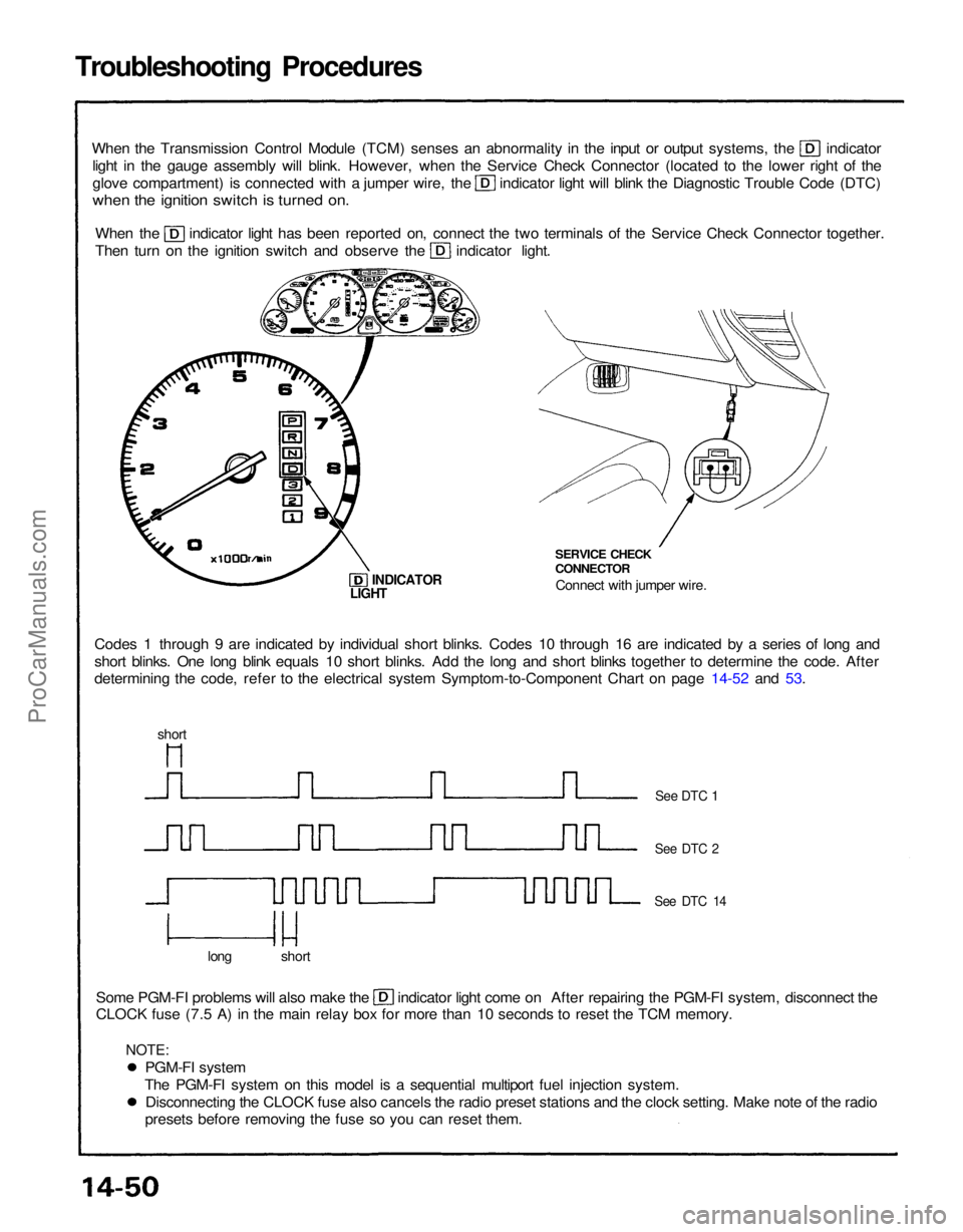
Troubleshooting Procedures
When the Transmission Control Module (TCM) senses an abnormality in the input or output systems, the indicator
light in the gauge assembly will blink. However, when the Service Check Connector (located to the lower right of the glove compartment) is connected with a jumper wire, the indicator light will blink the Diagnostic Trouble Code (DTC)
when the ignition switch is turned on.
When the indicator light has been reported on, connect the two terminals of the Service Check Connector together.
Then turn on the ignition switch and observe the indicator light.
Codes 1 through 9 are indicated by individual short blinks. Codes 10 through 16 are indicated by a series of long and
short blinks. One long blink equals 10 short blinks. Add the long and short blinks together to determine the code. After
determining the code, refer to the electrical system Symptom-to-Component Chart on page 14-52 and 53. SERVICE CHECK
CONNECTOR
Connect with jumper wire.
INDICATOR
Some PGM-FI problems will also make the indicator light come on After repairing the PGM-FI system, disconnect the
CLOCK fuse (7.5 A) in the main relay box for more than 10 seconds to reset the TCM memory.
long short
See DTC 1
See DTC 2
See DTC 14
LIGHT
short
PGM-FI system
The PGM-FI system on this model is a sequential multiport fuel injection system. Disconnecting the CLOCK fuse also cancels the radio preset stations and the clock setting. Make note of the radio
presets before removing the fuse so you can reset them.
NOTE:ProCarManuals.com