1991 ACURA NSX relay
[x] Cancel search: relayPage 165 of 1640
Engine Coolant Refilling and Bleeding
CAUTION: When pouring engine coolant, be sure to
shut the relay box lid and not let coolant spill on the
electrical parts or the paint. If any coolant spills, rinse it
off immediately.
NOTE:
• Perform this maintenance when the engine is cool.
• Before replacing the coolant, turn the ignition ON,
slowly turn the climate control temperature knob to
90° and turn off the ignition. This will allow the
coolant in the heater to drain out with the rest of the
system.
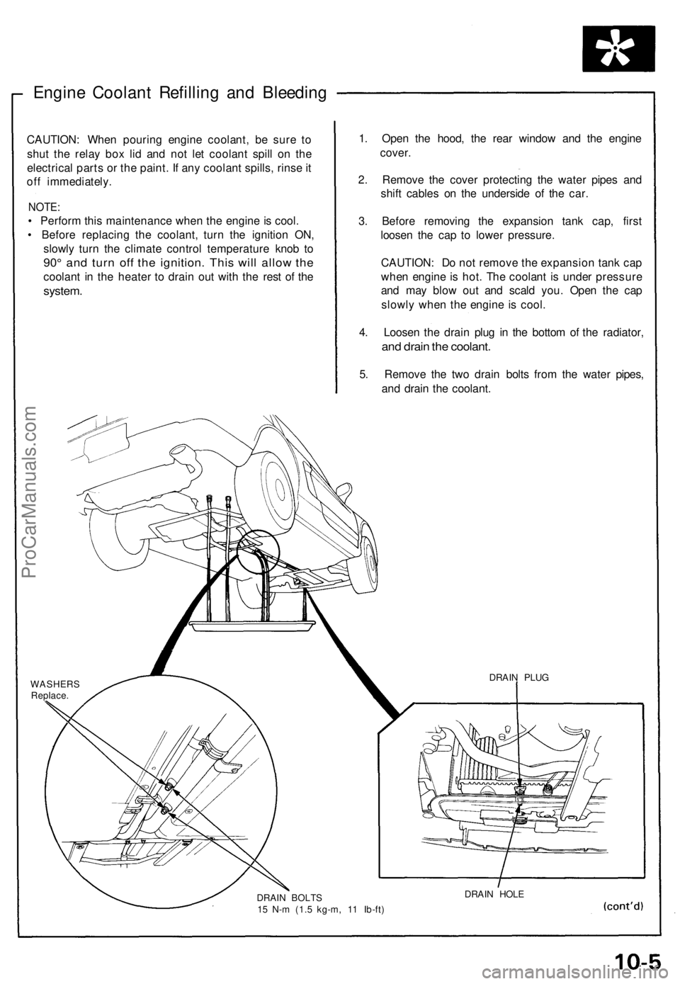
1. Open the hood, the rear window and the engine
cover.
2. Remove the cover protecting the water pipes and
shift cables on the underside of the car.
3. Before removing the expansion tank cap, first
loosen the cap to lower pressure.
CAUTION: Do not remove the expansion tank cap
when engine is hot. The coolant is under pressure
and may blow out and scald you. Open the cap
slowly when the engine is cool.
4. Loosen the drain plug in the bottom of the radiator,
and drain the coolant.
5. Remove the two drain bolts from the water pipes,
and drain the coolant.
WASHERS
Replace.
DRAIN BOLTS
15 N-m (1.5 kg-m, 11 Ib-ft)
DRAIN HOLE
DRAIN PLUGProCarManuals.com
Page 174 of 1640
Component Location s
Index
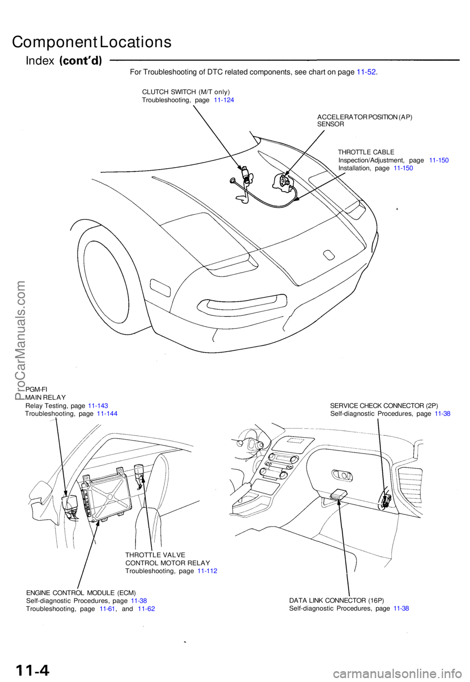
CLUTC H SWITC H (M/ T only )
Troubleshooting , pag e 11-12 4
ACCELERATOR POSITIO N (AP )
SENSO R
THROTTL E CABL EInspection/Adjustment , pag e 11-15 0
Installation , pag e 11-15 0
PGM-F I
MAI N RELA Y
Rela y Testing , pag e 11-14 3
Troubleshooting , pag e 11-14 4
THROTTLE VALVECONTROL MOTOR RELAY
Troubleshooting , pag e 11-11 2
ENGIN E CONTRO L MODUL E (ECM )
Self-diagnosti c Procedures , pag e 11-3 8
Troubleshooting , pag e 11-6 1, and 11-62 SERVIC
E CHEC K CONNECTO R (2P )
Self-diagnosti c Procedures , pag e 11-3 8
DAT A LIN K CONNECTO R (16P )
Self-diagnosti c Procedures , pag e 11-3 8
For Troubleshooting of DTC related components, see chart on page 11-52.
ProCarManuals.com
Page 208 of 1640
II. Engine Control Module (ECM) Reset Procedure
Either of the following actions, will reset the ECM.
• Using the OBD-II scan tool or Honda PGM Tester to clear the ECM's memory.
NOTE: See the OBD-II scan tool or Honda PGM Tester user's manuals for specific operating instructions.
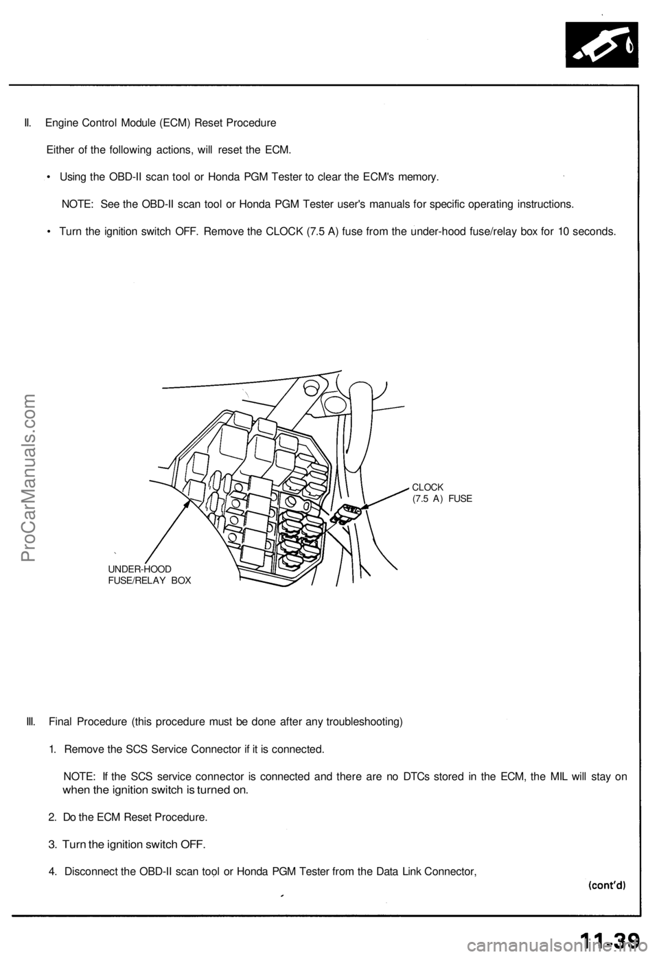
• Turn the ignition switch OFF. Remove the CLOCK (7.5 A) fuse from the under-hood fuse/relay box for 10 seconds.
UNDER-HOOD
FUSE/RELAY BOX
CLOCK
(7.5 A) FUSE
III. Final Procedure (this procedure must be done after any troubleshooting)
1. Remove the SCS Service Connector if it is connected.
NOTE: If the SCS service connector is connected and there are no DTCs stored in the ECM, the MIL will stay on
when the ignition switch is turned on.
2. Do the ECM Reset Procedure.
3. Turn the ignition switch OFF.
4. Disconnect the OBD-II scan tool or Honda PGM Tester from the Data Link Connector,ProCarManuals.com
Page 228 of 1640

PGM-FI System
System Description
PGM-FI System
The PGM-FI system on this model is a sequential multiport fuel injection system.
Fuel Injector Timing and Duration
The ECM contains memories for the basic discharge durations at various engine speeds and manifold pressures. The
basic discharge duration, after being read out from the memory, is further modified by signals sent from various sensors
to obtain the final discharge duration.
Throttle Valve Control
The ECM controls the throttle valve control motor based on accelerator pedal position, TCS control unit and various sig-
nals. The ECM also controls the idle control function, cruise control function, and other functions with the throttle valve
control.
Ignition Timing Control
• The ECM contains memories for basic ignition timing at various engine speeds and manifold pressures. Ignition timing
is also adjusted for engine coolant temperature.
• A knock control system is also used. When detonation is detected by the knock sensor (KS), the ignition timing is
retarded.
Other Control Functions
1. Starting Control
When the engine is started, the ECM provides a rich mixture by increasing fuel injector duration.
2. Fuel Pump Control
• When the ignition switch is initially turned on, the ECM supplies ground to the PGM-FI main relay that supplies
current to the fuel pump for two seconds to pressurize the fuel system.
• When the engine is running, the ECM supplies ground to the PGM-FI main relay that supplies current to the fuel pump.
• When the engine is not running and the ignition is on, the ECM cuts ground to the PGM-FI main relay which cuts
current to the fuel pump.
• Excellent engine performance is achieved through the use of VTEC (Variable Valve Timing and Valve Lift Electronic
Control System), intake air bypass control and discharge volume control of the fuel pump.ProCarManuals.com
Page 230 of 1640
Engine Control Module (ECM)
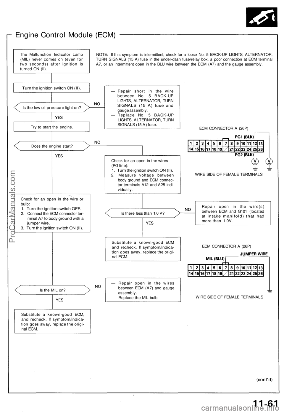
NOTE: If this symptom is intermittent, check for a loose No. 5 BACK-UP LIGHTS, ALTERNATOR,
TURN SIGNALS (15 A) fuse in the under-dash fuse/relay box, a poor connection at ECM terminal
A7, or an intermittent open in the BLU wire between the ECM (A7) and the gauge assembly.
Is the low oil pressure light on?
Try to start the engine.
Does the engine start?
Check for an open in the wire or
bulb:
1. Turn the ignition switch OFF.
2. Connect the ECM connector ter-
minal A7 to body ground with a
jumper wire.
3. Turn the ignition switch ON (II).
Is the MIL on?
Substitute a known-good ECM,
and recheck. If symptom/indica-
tion goes away, replace the origi-
nal
ECM.
— Repair short in the wire
between No. 5 BACK-UP
LIGHTS, ALTERNATOR, TURN
SIGNALS (15 A) fuse and
gauge assembly.
— Replace No. 5 BACK-UP
LIGHTS, ALTERNATOR, TURN
SIGNALS (15 A) fuse.
ECM CONNECTOR A (26P)
Check for an open in the wires
(PG line):
1. Turn the ignition switch ON (II).
2. Measure voltage between
body ground and ECM connec-
tor terminals A12 and A25 indi-
vidually.
WIRE SIDE OF FEMALE TERMINALS
Is there less than 1.0 V?
Repair open in the wire(s)
between ECM and G101 (located
at intake manifold) that had
more than 1.0V.
— Repair open in the wires
between ECM (A7) and gauge
assembly.
— Replace the MIL bulb.
WIRE SIDE OF FEMALE TERMINALS
ECM CONNECTOR A (26P)
Substitute a known-good ECM
and recheck. If symptom/indica-
tion goes away, replace the origi-
nal
ECM.
Turn the ignition switch ON (II).
The Malfunction Indicator Lamp
(MIL) never comes on (even for
two seconds) after ignition is
turned ON (II).ProCarManuals.com
Page 232 of 1640
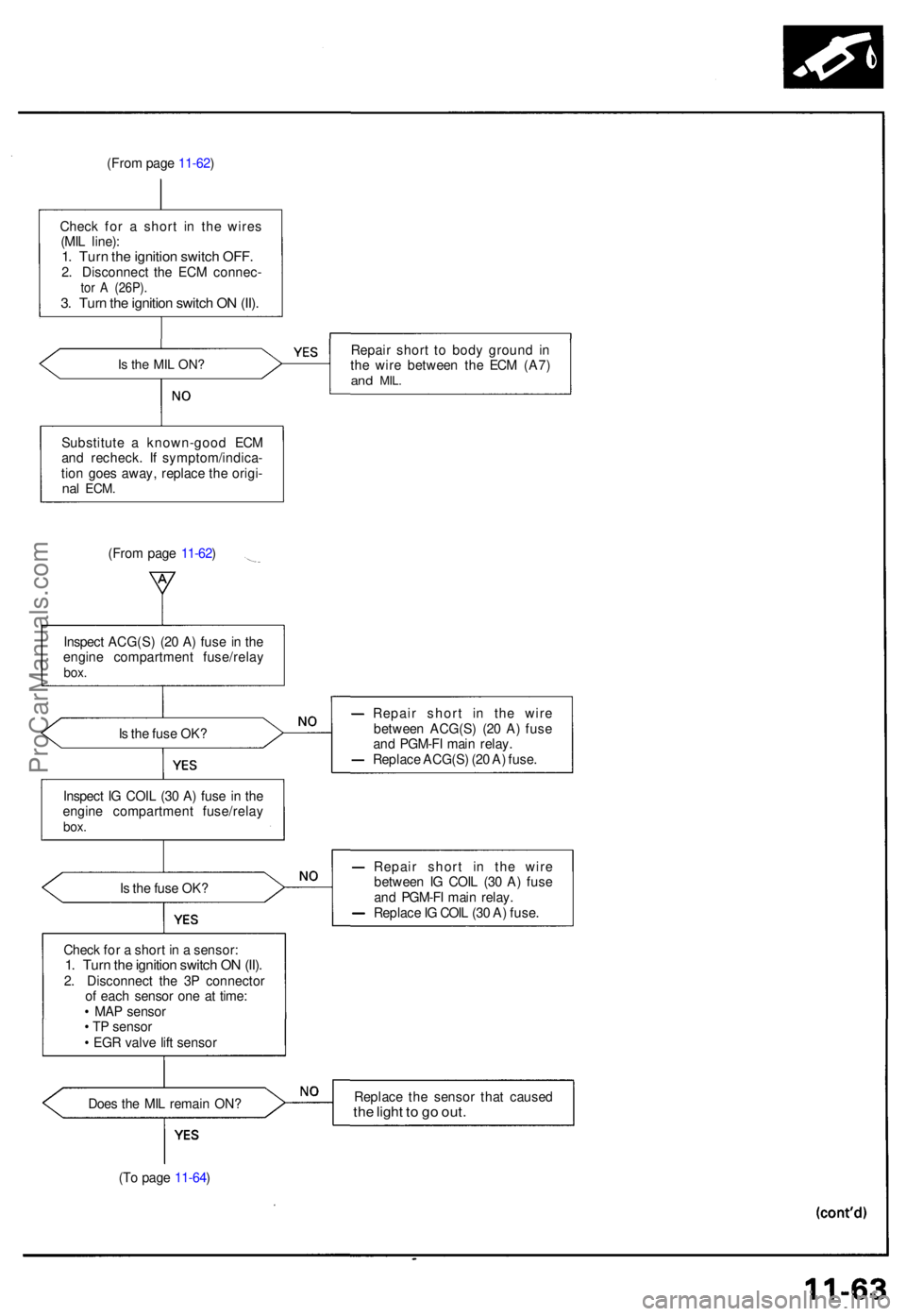
(From pag e 11-62 )
Chec k fo r a shor t i n th e wire s
(MI L line) :
1. Tur n th e ignitio n switc h OFF .2. Disconnec t th e EC M connec -tor A (26P) .3. Tur n th e ignitio n switc h O N (II) .
Is th e MI L ON ?Repai r shor t t o bod y groun d i n
th e wir e betwee n th e EC M (A7 )
and MIL .
Substitut e a known-goo d EC M
an d recheck . I f symptom/indica -
tio n goe s away , replac e th e origi -
nal ECM .
(From pag e 11-62 )
Inspec t ACG(S ) (2 0 A ) fus e i n th e
engin e compartmen t fuse/rela y
box.
Is th e fus e OK ? Repai
r shor t i n th e wir e
betwee n ACG(S ) (2 0 A ) fus e
an d PGM-F I mai n relay .
Replac e ACG(S ) (2 0 A ) fuse .
Inspec t I G COI L (3 0 A ) fus e i n th e
engin e compartmen t fuse/rela y
box.
Is th e fus e OK ? Repai
r shor t i n th e wir e
betwee n I G COI L (3 0 A ) fus e
an d PGM-F I mai n relay .
Replac e IG COI L (3 0 A ) fuse .
Chec k fo r a shor t i n a sensor :
1. Tur n th e ignitio n switc h O N (II) .2. Disconnec t th e 3 P connecto r
o f eac h senso r on e a t time :
• MA P senso r
• T P senso r
• EG R valv e lif t senso r
Doe s th e MI L remai n ON ? Replac
e th e senso r tha t cause d
the ligh t t o g o out .
(To pag e 11-64 )
ProCarManuals.com
Page 233 of 1640
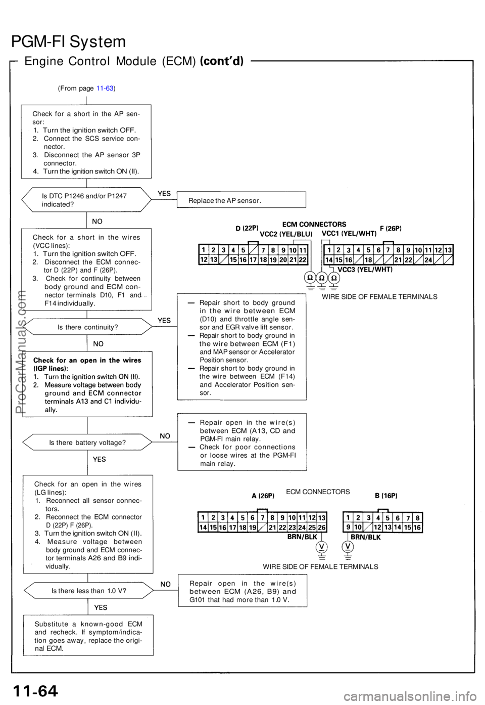
PGM-FI Syste m
Engine Contro l Modul e (ECM )
(From pag e 11-63 )
Chec k fo r a shor t i n th e A P sen -
sor:1. Tur n th e ignitio n switc h OFF .2. Connec t th e SC S servic e con -
nector .
3 . Disconnec t th e A P senso r 3 P
connector .
4. Tur n th e ignitio n switc h O N (II) .
Is DT C P124 6 and/o r P124 7
indicated ?
Chec k fo r a shor t i n th e wire s
(VC C lines) :
1. Tur n th e ignitio n switc h OFF .2. Disconnec t th e EC M connec -tor D (22P ) an d F (26P) .3. Chec k fo r continuit y betwee nbody groun d an d EC M con -necto r terminal s D10 , F 1 an dF14 individually .
Is ther e continuity ?
I s ther e batter y voltage ?
Chec k fo r a n ope n i n th e wire s
(L G lines) :
1 . Reconnec t al l senso r connec -
tors.2. Reconnec t th e EC M connecto rD (22P ) F (26P) .3. Tur n th e ignitio n switc h O N (II) .4. Measur e voltag e betwee n
bod y groun d an d EC M connec -
tor terminal s A2 6 an d B 9 indi -vidually .
I s ther e les s tha n 1. 0 V ?
Substitut e a known-goo d EC M
an d recheck . I f symptom/indica -
tio n goe s away , replac e th e origi -
nal ECM .
Replac e th e A P sensor .
Repai r shor t t o bod y groun d
in th e wir e betwee n EC M(D10 ) an d throttl e angl e sen -
so r an d EG R valv e lif t sensor .
Repai r shor t t o bod y groun d in
th e wir e betwee n EC M (F1 )and MA P senso r o r Accelerato r
Positio n sensor .
Repai r shor t t o bod y groun d in
th e wir e betwee n EC M (F14 )
an d Accelerato r Positio n sen -
sor.
WIR E SID E O F FEMAL E TERMINAL S
Repai r ope n i n th e wire(s )
between EC M (A13 , C D an dPGM-F I mai n relay .
Chec k fo r poo r connection s
o r loos e wire s a t th e PGM-F I
mai n relay .
ECM CONNECTOR S
WIR E SID E O F FEMAL E TERMINAL S
Repai r ope n i n th e wire(s )
between EC M (A26 , B9 ) an dG10 1 tha t ha d mor e tha n 1. 0 V .
ProCarManuals.com
Page 234 of 1640
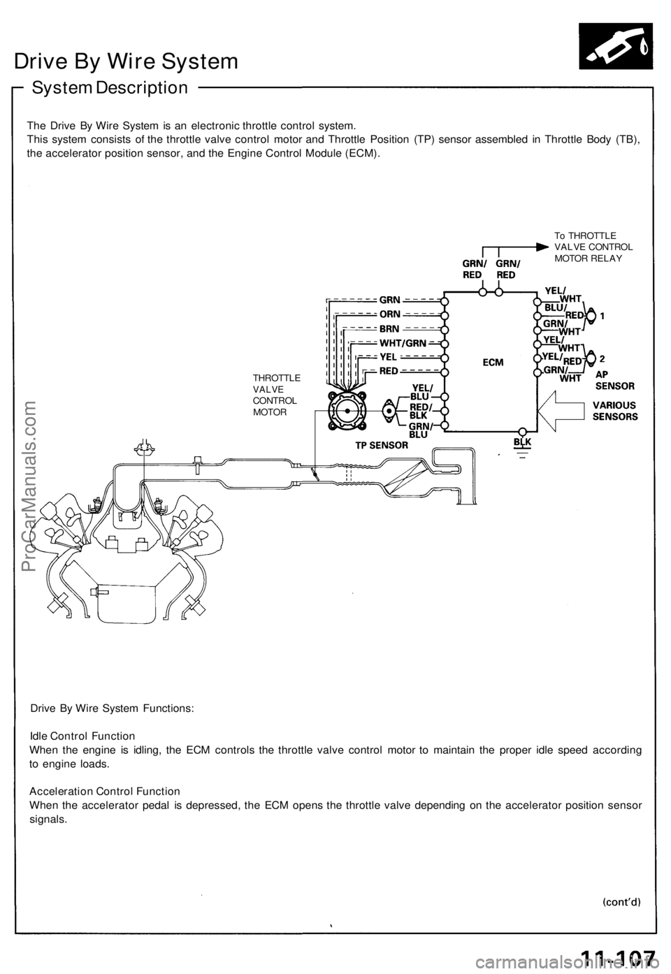
Drive By Wire System
System Description
The Drive By Wire System is an electronic throttle control system.
This system consists of the throttle valve control motor and Throttle Position (TP) sensor assembled in Throttle Body (TB),
the accelerator position sensor, and the Engine Control Module (ECM).
To THROTTLE
VALVE CONTROL
MOTOR RELAY
THROTTLE
VALVE
CONTROL
MOTOR
Drive By Wire System Functions:
Idle Control Function
When the engine is idling, the ECM controls the throttle valve control motor to maintain the proper idle speed according
to engine loads.
Acceleration Control Function
When the accelerator pedal is depressed, the ECM opens the throttle valve depending on the accelerator position sensor
signals.ProCarManuals.com