Page 841 of 1640
Headlight Relay Test
1. Remove the headlight relay from the under-hood
fuse/relay box.
2. Check continuity at the relay terminals.
• There should be continuity between the C and D
terminals.
• There should be continuity between the A and B
terminals when power and ground are connect-
ed to the C and D terminals.
• There should be no continuity between the A and
B terminals when power is disconnected.
Dimmer Relay Test
1. Remove the dimmer relay from the under-hood
fuse/relay box.
2. Check continuity at the relay terminals.
• There should be continuity between the F and E
terminals and between the B and C terminals.
• There should be continuity between the A and C
terminals when power and ground are connect-
ed to the E and F terminals.
• There should be no continuity between the A and
C terminals when power is disconnected.ProCarManuals.com
Page 842 of 1640

Lighting Syste m
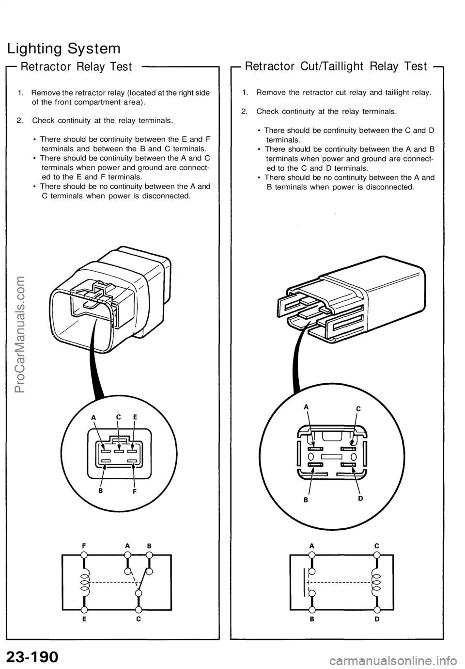
Retracto r Rela y Tes t
1. Remov e th e retracto r rela y (locate d a t th e righ t sid e
o f th e fron t compartmen t area) .
2 . Chec k continuit y a t th e rela y terminals .
• Ther e shoul d b e continuit y betwee n th e E an d F
terminal s an d betwee n th e B an d C terminals .
• Ther e shoul d b e continuit y betwee n th e A an d C
terminal s whe n powe r an d groun d ar e connect -
e d t o th e E an d F terminals .
• Ther e shoul d b e n o continuit y betwee n th e A an d
C terminal s whe n powe r i s disconnected .
Retractor Cut/Tailligh t Rela y Tes t
1. Remov e th e retracto r cu t rela y an d tailligh t relay .
2 . Chec k continuit y a t th e rela y terminals .
• Ther e shoul d b e continuit y betwee n th e C an d D
terminals .
• Ther e shoul d b e continuit y betwee n th e A an d B
terminal s whe n powe r an d groun d ar e connect -
e d t o th e C an d D terminals .
• Ther e shoul d b e n o continuit y betwee n th e A an d
B terminal s whe n powe r i s disconnected .
ProCarManuals.com
Page 845 of 1640
Headlight Replacement
CAUTION:
• Halogen headlights can become very hot in use; do
not touch them or the attaching hardware immediately
after they have been turned off.
• Do not try to replace or clean the headlights with the
lights on.
1. Remove the No. 42 (15 A) and No. 43 (15 A) fuses
from the under-hood fuse/relay box.
No. 43
(15A)
FUSE
No. 42
(15A)
FUSE
UNDER-HOOD FUSE/RELAY BOX
2. Remove the cap, and turn the knob clockwise to
raise the headlight.
CAP
RETRACTOR
KNOB
3. Remove the two caps, four screws, and cowl clips.
COWL CLIP
CAPS
SCREW
4. Slide the headlight housing forward and up to re-
move it. Be careful not to damage the bumper or the
housing.
HEADLIGHT HOUSING
PROTECTIVE TAPE
5. Disconnect the 6-P connector from the headlight
unit.
6-P CONNECTOR
MOUNTING
BOLTS
HEADLIGHT UNIT
6. Remove the four mounting bolts, then remove the
headlight unit.
7. After installing the new headlight, adjust both head-
lights to local requirements.ProCarManuals.com
Page 860 of 1640

(G551) '95-'96 Models.
(G401,G402,G551) '93-94 Models or
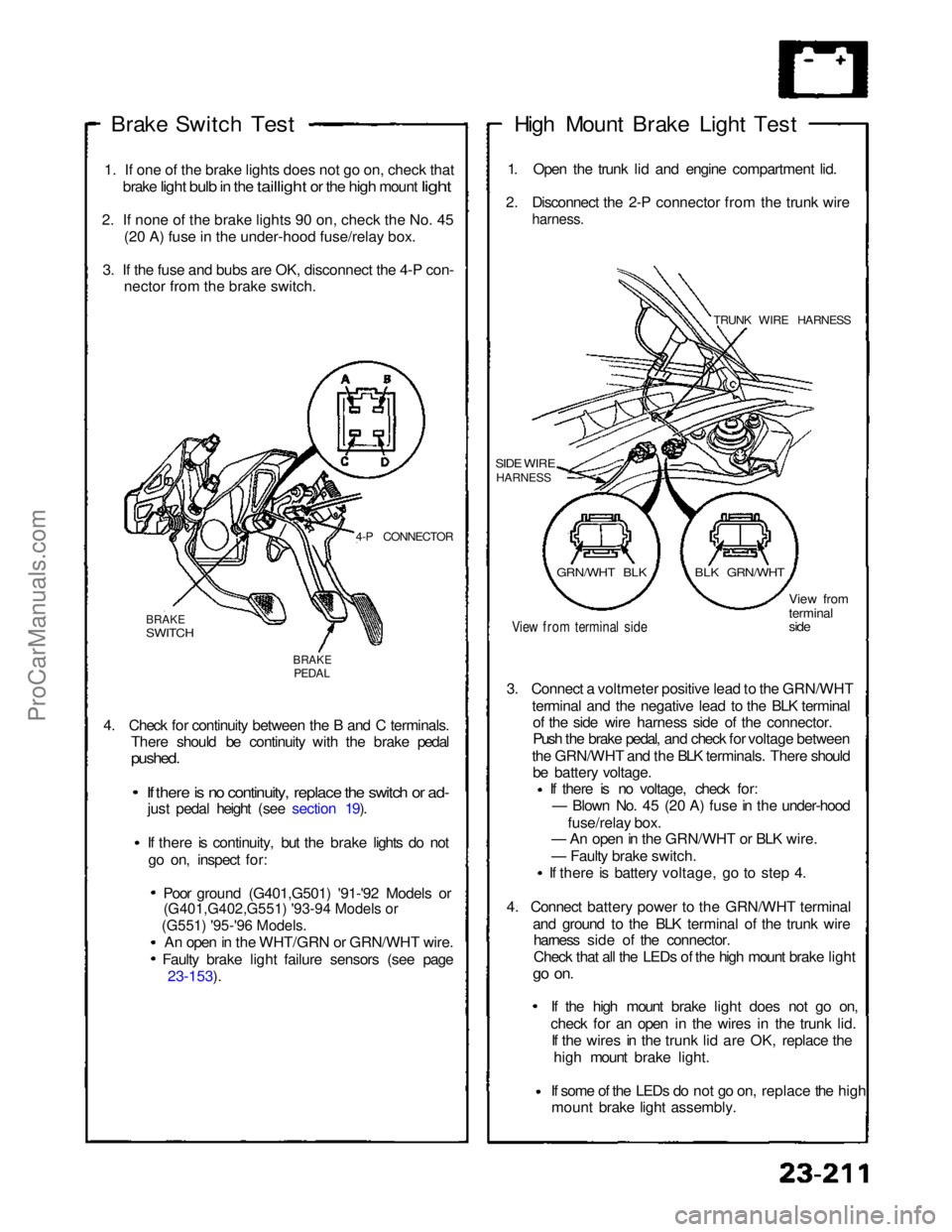
Brake Switch
Test
1
.
If one of the brake lights does not go on, check that
brake
light bulb in the taillight or the high mount light
2
.
If none of the brake lights 90 on, check the No. 45 (2
0
A) fuse in the under-hood fuse/relay box.
3
.
If the fuse and bubs are OK, disconnect the 4-P con- necto
r
from the brake switch.
4-P CONNECTOR
BRAKE
SWITCH
BRAKE
PEDAL
4. Check for continuity between the B and C terminals. There should be continuity with the brake pedal
pushed.
If there is no continuity, replace the switch or ad-
just pedal height (see section 19).
If there is continuity, but the brake lights do not
go on, inspect for:
Poor ground (G401,G501) '91-'92 Models or
An open in the WHT/GRN or GRN/WHT wire. Faulty brake light failure sensors (see page 23-153). High Mount Brake Light Test
1. Open the trunk lid and engine compartment lid.
2. Disconnect the 2-P connector from the trunk wire
harness.
TRUNK WIRE HARNESS
SIDE WIRE
HARNESS
View from terminal side
View from
terminal
side
3. Connect a voltmeter positive lead to the GRN/WHT terminal and the negative lead to the BLK terminalof the side wire harness side of the connector.
Push the brake pedal, and check for voltage between
the GRN/WHT and the BLK terminals. There should be battery voltage. If there is no voltage, check for:
— Blown No. 45 (20 A) fuse in the under-hood
fuse/relay box.
— An open in the GRN/WHT or BLK wire.
— Faulty brake switch.
If there is battery voltage, go to step 4.
4. Connect battery power to the GRN/WHT terminal and ground to the BLK terminal of the trunk wireharness side of the connector.
Check that all the LEDs of the high mount brake light
go on.
If the high mount brake light does not go on,check for an open in the wires
in the trunk lid.
If the wires in the trunk lid are OK, replace the
high mount brake light.
If some of the LEDs do not go on,
replace the high
mount brake light assembly.
GRN/WHT BLK
BLK GRN/WHTProCarManuals.com
Page 862 of 1640
Side Marker/Turn Signal/Hazard Flasher System
Component Location Index
SRS components are located in this area. Review the SRS component locations, precautions, and procedures in the SRS
section (24) before performing repairs or service.
TURN SIGNAL INDICATOR LIGHTS(In the gauge assembly)
Gauge Assembly, page 23-125 HAZARD WARNING SWITCH
Removal, page 23-220
Test, page 23-221
HEADLIGHT SWITCH
Test, page 23-181
Replacement, page 23-182
TURN SIGNAL/HAZARD RELAY
Input Test, page 23-218
UNDER-DASH FUSE BOX TURN SIGNAL SWITCH
Test, page 23-181
Replacement, page 23-182 TURN SIGNAL CANCEL UNIT
Input Test, page 23-219
SIDE MARKER FLASHER CIRCUIT
(In the integrated control unit)
Input Test, page 23-168 ('94-'96) ('91-'93)ProCarManuals.com
Page 865 of 1640
Side Marker/Turn Signal/Hazard Flasher System
Turn Signal/Hazard Relay Input Test
1. Remove the dashboard lower cover. Remove the
turn signal/hazard relay from the left kick panel,
then disconnect the 6-P connector.
2. Inspect the connector and socket terminals to be
sure they are all making good contact.
• If the terminals are bent, loose or corroded, repair
them as necessary, and recheck the system.
• If the terminals look OK, make the following input
tests at the connector.
— If any test indicates a problem, find and cor-
rect the cause, then recheck the system.
— If all the input tests prove OK, the control unit
must be faulty; replace it.
TURN/SIGNAL
HAZARD RELAY
View from
wire side
No. Terminal
Test condition
Test: Desired result
Possible cause if result is not obtainedProCarManuals.com
Page 878 of 1640
Cigarette Lighte r
Relay Tes t
1. Remov e th e glov e bo x (se e sectio n 20 ).
2 . Disconnec t th e 4- P connecto r fro m th e cigarett e
lighte r rela y (wir e color s o f 4- P connector : BLU /
GRN, YEL/RED , BRN/YEL , BLK) .
3. Chec k continuit y a t th e rela y terminals .
• Ther e shoul d b e continuit y betwee n th e C an d D
terminals .
• Ther e shoul d b e continuit y betwee n th e A an d B
terminal s whe n powe r an d groun d ar e connecte d
t o th e C an d D terminals .
• Ther e shoul d b e n o continuit y betwee n th e A
an d B terminal s whe n powe r i s disconnected .
ProCarManuals.com
Page 882 of 1640
Stereo Sound System
Unit Terminals
For MAST
ANTENNA
DIN CONNECTOR
(for CD CHANGER)
For WINDOW
ANTENNA
Terminal Wire
Connects to
Power Amplifier Relay Test
1. Remove the power amplifier relay from under-hood
relay box 8.
2. Check continuity at the relay terminals.
• There should be continuity between the C and D
terminals.
• There should be continuity between the A and B
terminals when power and ground are connect-
ed to the C and D terminals.
• There should be no continuity between the A and
B terminals when power is disconnected.ProCarManuals.com