Page 612 of 1640
. Disconnect the connec-
tor between the airbag and cable reel, then con-
nect the short connector (RED) to the airba")
Replacement
NOTE:
Remove the access panel, then remove the
short connector (RED). Disconnect the connec-
tor between the airbag and cable reel, then con-
nect the short connector (RED) to the airbag
connector.
AIRBAG
CONNECTOR
CABLE REEL
CONNECTOR
ACCESS PANEL
SHORT CONNECTOR
(RED)
Connect the special tool to the cable reel
connector.
CABLE REEL
CONNECTOR
SHORT
CONNECTOR
(RED)
SHS
SERVICE CONNECTOR
07MAZ–SP00200
(cont'd)
SRS components are located in this area. Review the SRS
component locations, precautions, and procedures in the
SRS section (24) before performing repairs or service.
1. To remove the dashboard, first remove the: Seats (see page 20-39 ('93-'96), 38)
Dashboard lower cover (Driver's) (see page
20-54('94-'96) ('91-'93))
Dashboard lower pad (see page 20-54('94-'96) ('91-'93))
Dashboard brace (see page 20-54('94-'96)('91-'93))
Cente
r
armrest (see page 20-49('94-'96)('91-'93))
Clock, center air vent and console panel (see
pages 20-50('94-'96) ('91-'93), 51('94-'96) ('91-'93)
52('94-'96) ('91-'93))
Climate control unit and stereo elassette/ratio (see
page 20-53('94-'96)('91-'93))
Dashboard lower cover (Passenger's) (see page
20-53('94-'96) ('91-'93))
Glove box lid and glove box (see page 20-53('94-'96)('91-'93))
2. Lower the Steering column (see section 17).
To avoid accidental deployment and
possible injury always install the short connector on the airbag connector when the SRS wire
harness is disconnected.ProCarManuals.com
Page 689 of 1640
Climate Contro l Uni t
Replacemen t
SRS component s ar e locate d in thi s area . Revie w th e SR S
componen t locations , precautions , an d procedure s in th e
SR S sectio n 24 befor e performin g repair s o r service .
1 . Remov e th e cloc k (se e sectio n 23 ).
2 . Remov e th e tw o screw s behin d th e clock , the n
remov e th e cente r ai r ven t (se e sectio n 20 ). 3
. Tak e ou t th e ashtra y an d remov e th e tw o screw s
fro m unde r th e ashtray .
ASHTRA Y
4. Remov e th e fou r screws , the n remov e th e cente r
armrest .
PAD
CENTE R ARMRES T
ProCarManuals.com
Page 712 of 1640
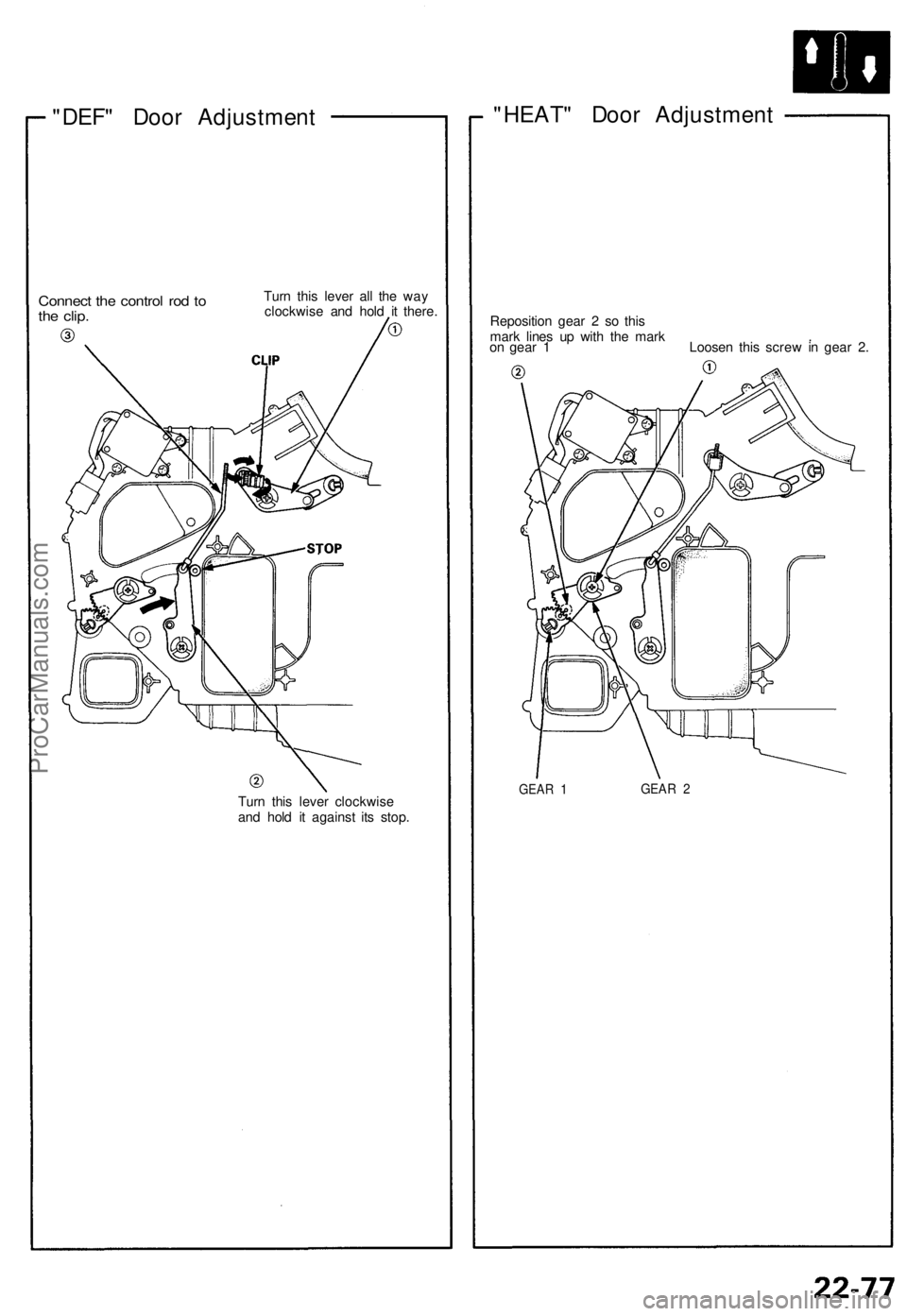
"DEF" Door Adjustment
Connect the control rod to
the clip.
Turn this lever all the way
clockwise and hold it there.
Turn this lever clockwise
and hold it against its stop.
"HEAT" Door Adjustment
Reposition gear 2 so this
mark lines up with the mark .
on gear 1 Loosen this screw in gear 2.
GEAR 1
GEAR 2ProCarManuals.com
Page 835 of 1640
Retractor Switch Test
1. Remove the retractor switch (see previous page).
2. Check for continuity between the terminals in each
switch position according to the table.
Retractor Switch
RETRACTOR SWITCH
Retractor Switch
Retractor Switch Light Bulb Replacement
1. Remove the retractor switch (see previous page).
2. Turn the bulb 45° counterclockwise to remove it.
RETRACTOR SWITCH
BULB (0.84W)ProCarManuals.com
Page 836 of 1640
Lighting System
Retractor Motor Replacement
CAUTION:
• Halogen headlights can become very hot in use; do
not touch them or the attaching hardware immediately
after they have been turned off.
• Do not try to replace or clean headlights with the lights
on.
1. Remove the No. 42 (15 A) and No. 43 (15 A) fuses
from the under-hood fuse/relay box.
No. 43
(15A)
FUSE
No. 42
(15A)
FUSE
UNDER-HOOD FUSE/RELAY BOX
2. Turn the knob clockwise to raise the headlight.
CAP
KNOB
3. Remove the two caps, four screws, and cowl clips.
COWL CLIP
CAP
SCREW
4. Slide the headlight housing forward and up.
NOTE: Be careful not to damage the front bumper
or the headlight housing.
HEADLIGHT HOUSING
PROTECTIVE TAPE
5. Disconnect the 6-P connector from the headlight
unit.
6-P CONNECTOR
HEADLIGHT UNIT
6. Remove the four mounting bolts, then remove the
unit.
MOUNTING
BOLTSProCarManuals.com
Page 840 of 1640
Lighting Syste m
Retracto r Moto r Tes t
1. Remov e th e retracto r motor .
2 . Tes t th e moto r b y connectin g batter y powe r t o th e
A termina l an d groun d t o th e D terminal .
Th e moto r shoul d ru n continuously .
3 . I f th e moto r doe s no t ru n o r fail s t o ru n smoothly ,
replace it .
NOTE : Th e illustratio n show s th e moto r i n th e con -
ditio n whe n th e headligh t i s full y raised .
RETRACTO RKNOB
View fro mtermina l sid e
BCTermina l
Position
At close d positio n
At ope n positio n
4. Disconnec t th e powe r supply , and chec k fo r con -
tinuit y betwee n th e terminal s accordin g t o th e ta -
bl e whil e turnin g th e retracto r kno b clockwise .
ProCarManuals.com
Page 845 of 1640
Headlight Replacement
CAUTION:
• Halogen headlights can become very hot in use; do
not touch them or the attaching hardware immediately
after they have been turned off.
• Do not try to replace or clean the headlights with the
lights on.
1. Remove the No. 42 (15 A) and No. 43 (15 A) fuses
from the under-hood fuse/relay box.
No. 43
(15A)
FUSE
No. 42
(15A)
FUSE
UNDER-HOOD FUSE/RELAY BOX
2. Remove the cap, and turn the knob clockwise to
raise the headlight.
CAP
RETRACTOR
KNOB
3. Remove the two caps, four screws, and cowl clips.
COWL CLIP
CAPS
SCREW
4. Slide the headlight housing forward and up to re-
move it. Be careful not to damage the bumper or the
housing.
HEADLIGHT HOUSING
PROTECTIVE TAPE
5. Disconnect the 6-P connector from the headlight
unit.
6-P CONNECTOR
MOUNTING
BOLTS
HEADLIGHT UNIT
6. Remove the four mounting bolts, then remove the
headlight unit.
7. After installing the new headlight, adjust both head-
lights to local requirements.ProCarManuals.com
Page 847 of 1640
Front Tur n Signal/Fron t
Parkin g Light s
Replacemen t
1. Remov e th e scre w an d pul l th e ligh t assembl y ou t
o f th e fron t bumper .
SCREW
2. Disconnec t th e 2- P connector s fro m th e bul b
sockets .
2-P CONNECTOR S
FRON T PARKIN G LIGH T
BUL B (5W )
BULBSOCKE T
FRON T TUR N SIGNA L
LIGH T BUL B (45CP )
HOUSIN G
3. Tur n th e bul b socket s 45 ° counterclockwis e t o re -
mov e the m fro m th e housing .
Front Sid e Marke r
Lights
Replacemen t
1. Carefull y pr y th e fron t sid e marke r ligh t ou t o f th e
fron t fender . B e carefu l no t t o damag e th e fron t sid e
marke r ligh t o r th e fron t fender .
PROTECTIV E CLOT H
FRON T SID E MARKE R LIGH T
2. Disconnec t th e 2- P connecto r fro m th e fron t sid e
marke r light .
2-P CONNECTO R
HOUSIN G
3. Tur n th e bul b socke t 45 ° counterclockwis e t o re -
mov e i t fro m th e housing .
BULB (3CP )
ProCarManuals.com

.
2. Check for continuity between the terminals in each
switch position according to the table.
Retractor Switch
RETRACTOR")


