Page 848 of 1640
Taillights
Replacement
1. Open the trunk lid, and remove the rear trim panel.
2. Disconnect the 8-P connector and 2-P connector
from the taillight assembly.
3. Disconnect the 2-P connector from the trunk key
cylinder switch.
8-P CONNECTOR
2-P CONNECTOR
TRUNK KEY CYLINDER
CONNECTOR
REAR TRIM PANEL
4. Remove the four mounting nuts and rear panel, then
remove the ten mounting nuts and the taillight as-
sembly.
NEW GASKET
REAR PANEL
TAILLIGHT ASSEMBLY
5. Inspect the gasket; if it is distorted or stays com-
pressed, replace it.
6. After installing, run water over the lights to make
sure they don't leak.
Bulb Replacement
1. Open the trunk lid, and remove the rear trim panel.
2. Turn each socket 45° counterclockwise to remove
them from the taillight housing.
SOCKET
TURN SIGNAL LIGHT BULB (45CP)
and BRAKE LIGHT/TAILLIGHT BULBS (32CP/2CP)
TAILLIGHT BULB (2CP)
BACK-UP LIGHT BULB (32CP)
3. Remove the bulbs from the sockets.ProCarManuals.com
Page 849 of 1640
Rear Side Marker Lights
Replacement
1. Carefully pry the rear side marker light out of the rear
fender. Be careful not to damage the rear parking
light or the rear fender.
Pry out here.
REAR SIDE
MARKER
LIGHT
REAR
BUMPER
PROTECTIVE CLOTH
2. Disconnect the 2-P connector from the rear side mar-
ker light.
SOCKET
2-P CONNECTOR
3. Turn the bulb socket 45° counterclockwise to re-
move it from the rear side marker light.
License Plate Lights
Replacement
1. Remove the eight screws, and disconnect the 4-P
connector.
LICENSE PLATE
LIGHT
4-P
CONNECTOR
REAR BUMPER
2. Turn the bulb socket 45° counterclockwise to re-
move it from the housing.
SOCKET
BULB (8W)
HOUSING
3. If necessary, separate the lens from the housing by
removing the two screws.
HOUSING
BULB (3CP)ProCarManuals.com
Page 873 of 1640
Dash Lights Brightness Control
Controller Test
1. Remove the dash lights brightness controller from
the instrument panel (see previous page).
2. Measure resistance between A and B terminals
while rotating the adjusting dial. Resistance should
vary from 0 to 20,000 ohms as the dial is rotated.
NOTE: Resistance will vary slightly with temperature.
HEADLIGHT
RETRACTOR SWITCH
ADJUSTING
DIAL
DASH LIGHTS
BRIGHTNESS
CONTROLLER
Dash lights brightness controller
Controller Light Bulb Replacement
1. Remove the dash lights brightness controller.
2. Turn the socket 45° counterclockwise to remove it.
BULB (0.84W)ProCarManuals.com
Page 876 of 1640
Removal
CAUTION: Be careful not to damage the center air vent
or clock.
1. Pull the clock out with your fingers (if necessary, use
a screwdriver).
2. Disconnect the 4-P connector from the clock.
4-P CONNECTOR
CENTER AIR VENT
Terminals
Terminal Wire Connects to
CLOCKProCarManuals.com
Page 877 of 1640

Replacement
SRS component s ar e locate d i n thi s area . Revie w th e
SR S componen t locations , precautions , an d procedure s
i n th e SR S sectio n 24 befor e performin g repair s o r ser -
vice .
1. Remov e th e cloc k (se e pag e 23-231 ).
2 . Remov e th e tw o screw s behin d th e clock , the n
remov e th e cente r ai r ven t (se e sectio n 20 ).
3 . Remov e th e fou r screws , the n remov e th e cente r
armrest .
4. Tak e ou t th e ashtray .
5 . Remov e th e fiv e screw s an d cente r consol e panel ,
the n disconnec t th e 3- P connecto r an d 4- P connec -
to r fro m th e floo r wir e harness .
ASHTRA Y
CENTERCONSOL EPANEL
CENTE R AI R VEN T
4- P CONNECTO R
3- P CONNECTO R
CENTE R ARMRES T
6. Disconnec t th e therm o fus e cas e fro m th e en d of
th e cigarett e lighte r socket .
7 . Remov e th e rin g nut , an d separat e th e cigarett e
lighte r socke t fro m th e therma l protector .
8 . Whe n installin g th e cigarett e lighter , alig n eac h lu g
o n th e fac e panel , illuminatio n rin g an d cigarett e
lighte r socke t wit h th e groov e in th e hole , the n posi -
tio n th e bul b housin g o n th e therma l protecto r
betwee n th e stop s o n th e cente r consol e panel .
9 . Mak e sur e tha t th e ground , bul b socke t an d therm o
fus e cas e ar e seate d agains t th e cigarett e lighte r
assembly .
CIGARETT ELIGHTERSOCKE T
ILLUMINATIO NRING
FACE PANE L
THERMA L
PROTECTO R
GROUNDWIRE
CENTE R CONSOL EPANELASHTRA Y LIGH T (1. 4 W )
RIN
G NU T
THERM O FUS E CAS E
CIGARETT E LIGHTE R
LIGH T (1. 4 W )
ProCarManuals.com
Page 880 of 1640
Stereo Soun d Syste m
Unit Remova l
SRS component s ar e locate d i n thi s area . Revie w th e
SR S componen t locations , precautions , an d procedure s
i n th e SR S sectio n 24 befor e performin g repair s o r ser -
vice .
1. Remov e th e cloc k (se e pag e 23-231 ).
2 . Remov e th e tw o screw s behin d th e clock , the n
remov e th e cente r ai r ven t (se e sectio n 20 ). 3
. Remov e th e fou r screws , the n remov e th e cente r
armrest .
PAD
CENTE R ARMRES T
4. Tak e ou t th e ashtray .
ASHTRA Y
ProCarManuals.com
Page 1008 of 1640

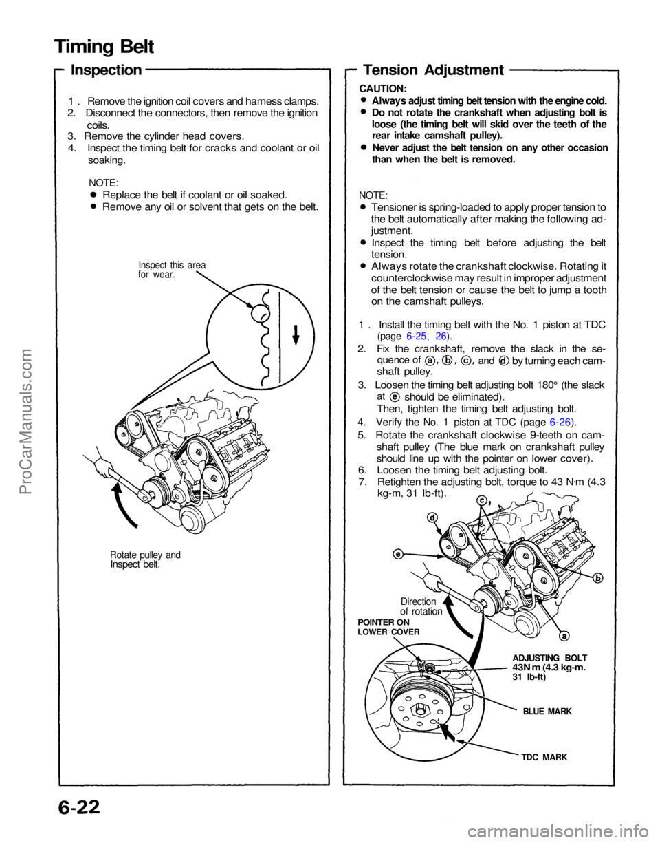
Rotate pulley and
Inspect belt.
for wear.
1 . Remove the ignition coil covers and harness clamps.
2. Disconnect the connectors, then remove the ignition
coils.
3. Remove the cylinder head covers.
4. Inspect the timing belt for cracks and coolant or oil
soaking.
NOTE:
TDC MARK
BLUE MARK
ADJUSTING BOLT
43N
.
m (4.3 kg-m.
31 Ib-ft)
Direction
of rotation
POINTER ON
LOWER COVER
Tension Adjustment
Always adjust timing belt tension with the engine cold.
Do not rotate the crankshaft when adjusting bolt is
loose (the timing belt will skid over the teeth of the
rear intake camshaft pulley).
Never adjust the belt tension on any other occasion
than when the belt is removed.
shaft pulley.
3. Loosen the timing belt adjusting bolt 180° (the slack
Then, tighten the timing belt adjusting bolt.
4. Verify the No. 1 piston at TDC (page 6-26).
5. Rotate the crankshaft clockwise 9-teeth on cam- shaft pulley (The blue mark on crankshaft pulley
should line up with the pointer on lower cover).
6. Loosen the timing belt adjusting bolt.
7. Retighten the adjusting bolt, torque to 43 N .
m (4.3
kg-m, 31 Ib-ft).
at
should be eliminated).
quence of
and
by turning each cam-
Replace the belt if coolant or oil soaked.
Remove any oil or solvent that gets on the belt.
Inspect this area
Timing Belt
Inspection
CAUTION:
NOTE:
Tensioner is spring-loaded to apply proper tension to
the belt automatically after making the following ad-
justment.
Inspect the timing belt before adjusting the belt
tension.
Always rotate the crankshaft clockwise. Rotating it
counterclockwise may result in improper adjustment
of the belt tension or cause the belt to jump a tooth on the camshaft pulleys.
1 . Install the timing belt with the No. 1 piston at TDC
(page 6-25, 26).
2. Fix the crankshaft, remove the slack in the se-ProCarManuals.com
Page 1011 of 1640

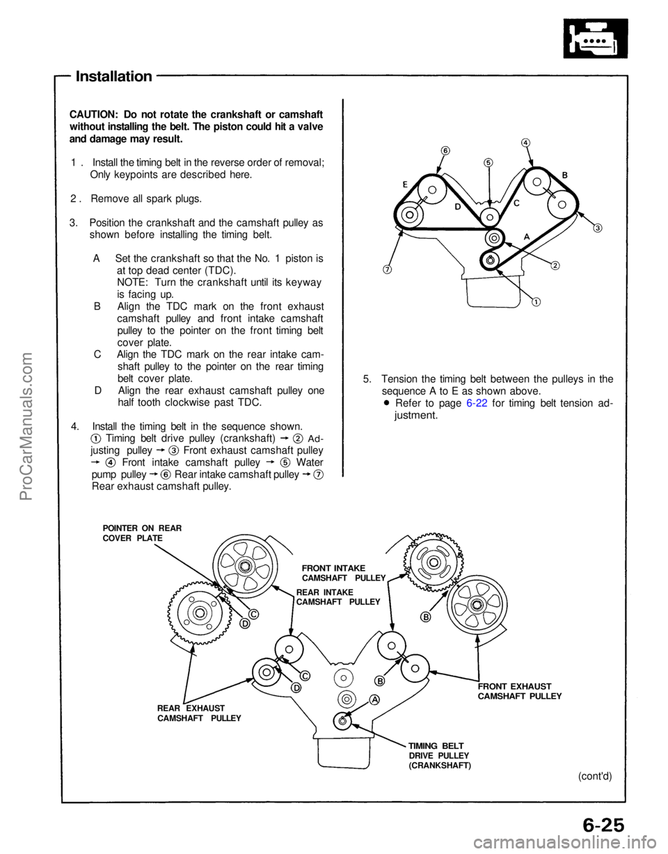
Installation
CAUTION: Do not rotate the crankshaft or camshaft without installing the belt. The piston could hit a valve
and damage may result.
1 . Install the timing belt in the reverse order of removal; Only keypoints are described here.
2 . Remove all spark plugs.
3. Position the crankshaft and the camshaft pulley as shown before installing the timing belt.
A Set the crankshaft so that the No. 1 piston is at top dead center (TDC).NOTE: Turn the crankshaft until its keyway
is facing up.
B Align the TDC mark on the front exhaust camshaft pulley and front intake camshaftpulley to the pointer on the front timing belt
cover plate.
C Align the TDC mark on the rear intake cam-
shaft pulley to the pointer on the rear timing
belt cover plate.
D Align the rear exhaust camshaft pulley one half tooth clockwise past TDC.
POINTER ON REAR
COVER PLATE
REAR EXHAUSTCAMSHAFT PULLEY
TIMING BELT
DRIVE PULLEY
(CRANKSHAFT)
FRONT EXHAUST
CAMSHAFT PULLEY
(cont'd)
5. Tension the timing belt between the pulleys in the
sequence A to E as shown above.
4. Install the timing belt in the sequence shown.
FRONT INTAKE
CAMSHAFT PULLEY
REAR INTAKE
CAMSHAFT PULLEY
Rear exhaust camshaft pulley.
Timing belt drive pulley (crankshaft)
Ad-
Water
justing pulley
Front intake camshaft pulley Front exhaust camshaft pulley
pump pulley Rear intake camshaft pulley Refer to page 6-22 for timing belt tension ad-
justment.ProCarManuals.com