Page 430 of 1640
Steering Wheel
Installation
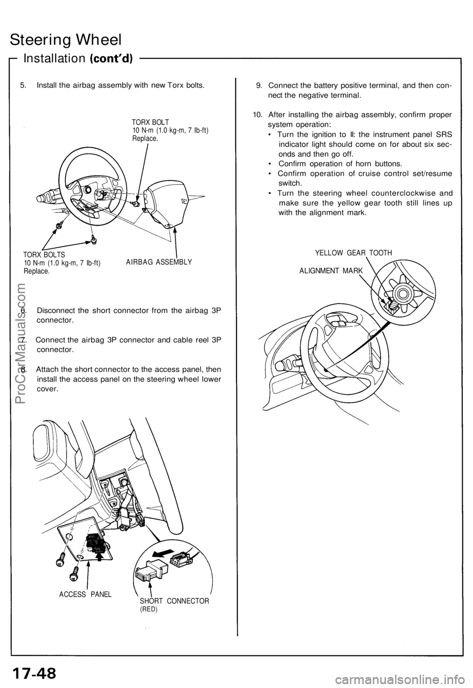
5. Install the airbag assembly with new Torx bolts.
TORX BOLT
10 N-m (1.0 kg-m, 7 Ib-ft)
Replace.
TORX BOLTS
10 N-m (1.0 kg-m, 7 Ib-ft)
Replace.
AIRBAG ASSEMBLY
6. Disconnect the short connector from the airbag 3P
connector.
7. Connect the airbag 3P connector and cable reel 3P
connector.
8. Attach the short connector to the access panel, then
install the access panel on the steering wheel lower
cover.
ACCESS PANEL
SHORT CONNECTOR
(RED)
9. Connect the battery positive terminal, and then con-
nect the negative terminal.
10. After installing the airbag assembly, confirm proper
system operation:
• Turn the ignition to II: the instrument panel SRS
indicator light should come on for about six sec-
onds and then go off.
• Confirm operation of horn buttons.
• Confirm operation of cruise control set/resume
switch.
• Turn the steering wheel counterclockwise and
make sure the yellow gear tooth still lines up
with the alignment mark.
YELLOW GEAR TOOTH
ALIGNMENT MARKProCarManuals.com
Page 506 of 1640
Rear Brak e Pad s
Inspection/Replacemen t (cont'd )
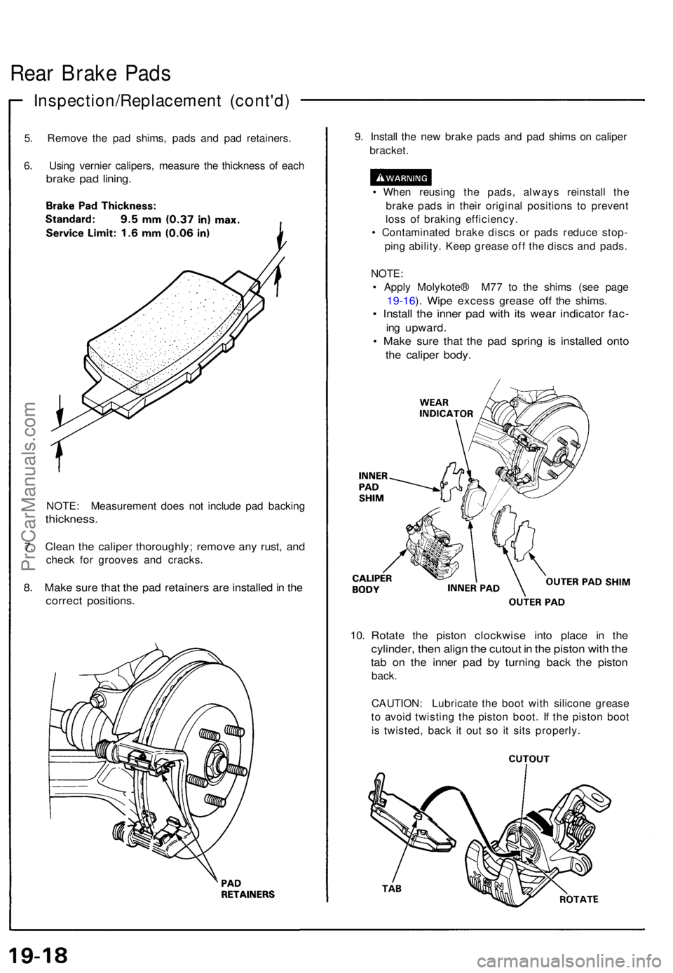
5. Remov e th e pa d shims , pad s an d pa d retainers .
6 . Usin g vernie r calipers , measur e th e thicknes s o f eac h
brak e pa d lining .
NOTE : Measuremen t doe s no t includ e pa d backin g
thickness .
7. Clea n th e calipe r thoroughly ; remov e an y rust , an d
chec k fo r groove s an d cracks .
8. Mak e sur e tha t th e pa d retainer s ar e installe d in th e
correc t positions .
9. Instal l th e ne w brak e pad s an d pa d shim s o n calipe r
bracket .
• Whe n reusin g th e pads , alway s reinstal l th e
brak e pad s i n thei r origina l position s t o preven t
los s o f brakin g efficiency .
• Contaminate d brak e disc s o r pad s reduc e stop -
pin g ability . Kee p greas e of f th e disc s an d pads .
NOTE :
• Appl y Molykote ® M7 7 t o th e shim s (se e pag e
19-16 ). Wip e exces s greas e of f th e shims .
• Instal l th e inne r pa d wit h it s wea r indicato r fac -
ing upward .
• Mak e sur e tha t th e pa d sprin g i s installe d ont o
the calipe r body .
10. Rotat e th e pisto n clockwis e int o plac e i n th e
cylinder , the n alig n th e cutou t i n th e pisto n wit h th e
tab o n th e inne r pa d b y turnin g bac k th e pisto n
back.
CAUTION : Lubricat e th e boo t wit h silicon e greas e
t o avoi d twistin g th e pisto n boot . I f th e pisto n boo t
i s twisted , bac k i t ou t s o i t sit s properly .
ProCarManuals.com
Page 514 of 1640
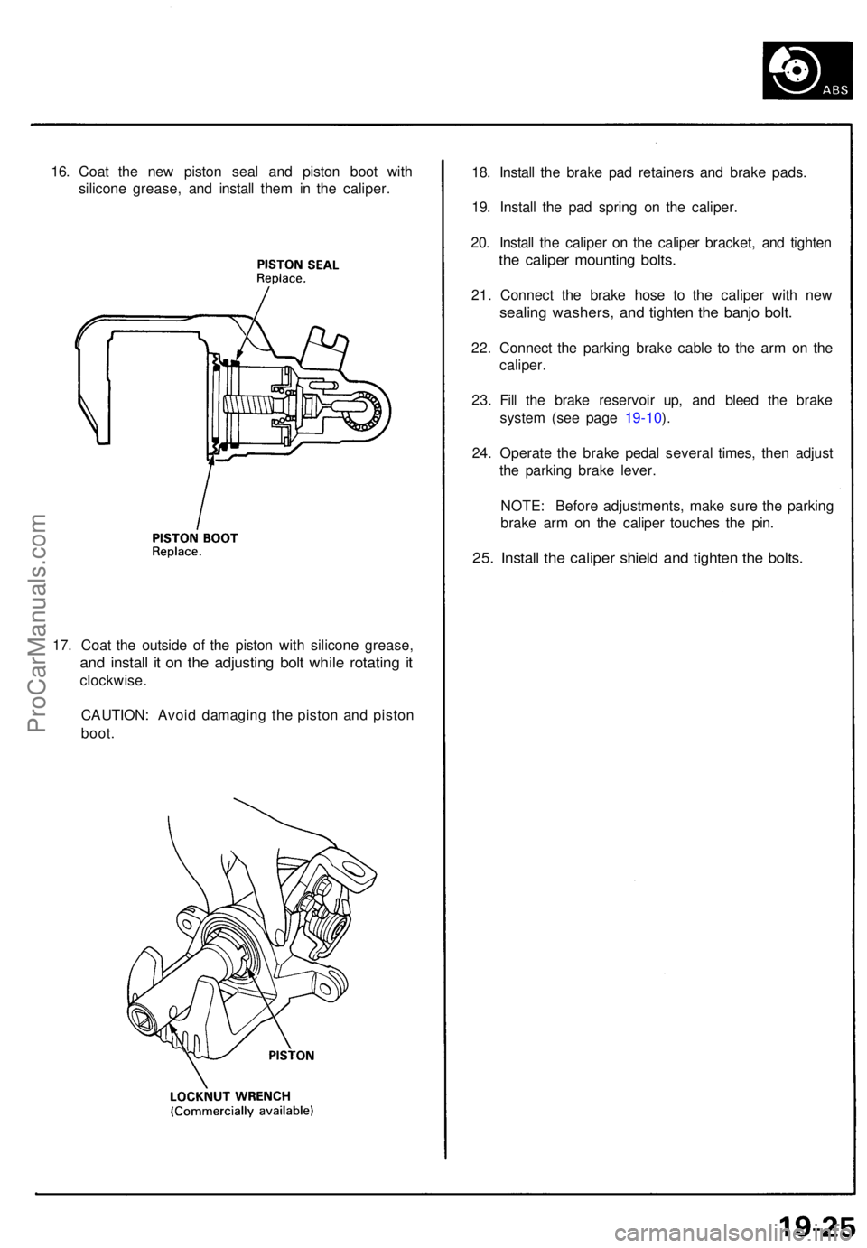
16. Coa t th e ne w pisto n sea l an d pisto n boo t wit h
silicon e grease , an d instal l the m in th e caliper .
17 . Coa t th e outsid e of the pisto n wit h silicon e grease ,
and instal l i t o n th e adjustin g bol t whil e rotatin g i t
clockwise .
CAUTION : Avoi d damagin g th e pisto n an d pisto n
boot.
18. Instal l th e brak e pa d retainer s an d brak e pads .
19 . Instal l th e pa d sprin g o n th e caliper .
20 . Instal l th e calipe r o n th e calipe r bracket , an d tighte n
the calipe r mountin g bolts .
21. Connec t th e brak e hos e t o th e calipe r wit h ne w
sealin g washers , an d tighte n th e banj o bolt .
22. Connec t th e parkin g brak e cabl e t o th e ar m o n th e
caliper .
23 . Fil l th e brak e reservoi r up , an d blee d th e brak e
syste m (se e pag e 19-10 ).
24 . Operat e th e brak e peda l severa l times , the n adjus t
th e parkin g brak e lever .
NOTE : Befor e adjustments , mak e sur e th e parkin g
brak e ar m o n th e calipe r touche s th e pin .
25. Instal l th e calipe r shiel d an d tighte n th e bolts .
ProCarManuals.com
Page 575 of 1640
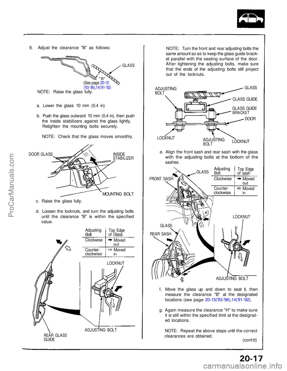
9. Adjust the clearance "B" as follows:
GLASS
a. Lower the glass 10 mm (0.4 in)
b. Push the glass outward 10 mm (0.4 in), then push the inside stabilizers against the glass lightly.Retighten the mounting bolts securely.
NOTE: Check that the glass moves smoothly.
DOOR GLASS
INSIDE
STABILIZER
MOUNTING BOLT
c. Raise the glass fully.
d. Loosen the locknuts, and turn the adjusting bolts until the clearance "B" is within the specified
value.
LOCKNUT
ADJUSTING BOLT
REAR GLASS
GUIDE
NOTE: Turn the front and rear adjusting bolts the
same amount so as to keep the glass guide brack-
et parallel with the seating surface of the door.
After tightening the adjusting bolts, make sure
that the ends of the adjusting bolts still project
out of the locknuts.
ADJUSTING
BOLT
GLASS
CLASS GUIDE
LOCKNUT
ADJUSTING
BOLT
GLASS GUIDE
BRACKET
DOOR
LOCKNUT
e. Align the front sash and rear sash with the glass
with the adjusting bolts at the bottom of the
sashes.
FRONT SASH
ADJUSTING BOLT
f. Move the glass up and down to seat it, then measure the clearance "B" at the designated
locations (see page 20-15('93-'96),14('91-'92).
g. Again measure the clearance "H" to make sure it is still within the specified limit at the designat-
ed locations.
NOTE: Repeat the above steps until the correct
clearances are obtained. (cont'd)
(See page 20-15
('93-'96),14('91-'92)
NOTE: Raise the glass fully.
Adjusting
Bolt
Top Edge
of Glass
Clockwise
Moved
out
Counter-
clockwise
Moved
in
LOCKNUT
GLASS
REAR SASH
GLASS
Adjusting
Bolt
Top Edge
of sash
Clockwise
Moved
out
Counter-
clockwise
Moved
in
"B"ProCarManuals.com
Page 603 of 1640
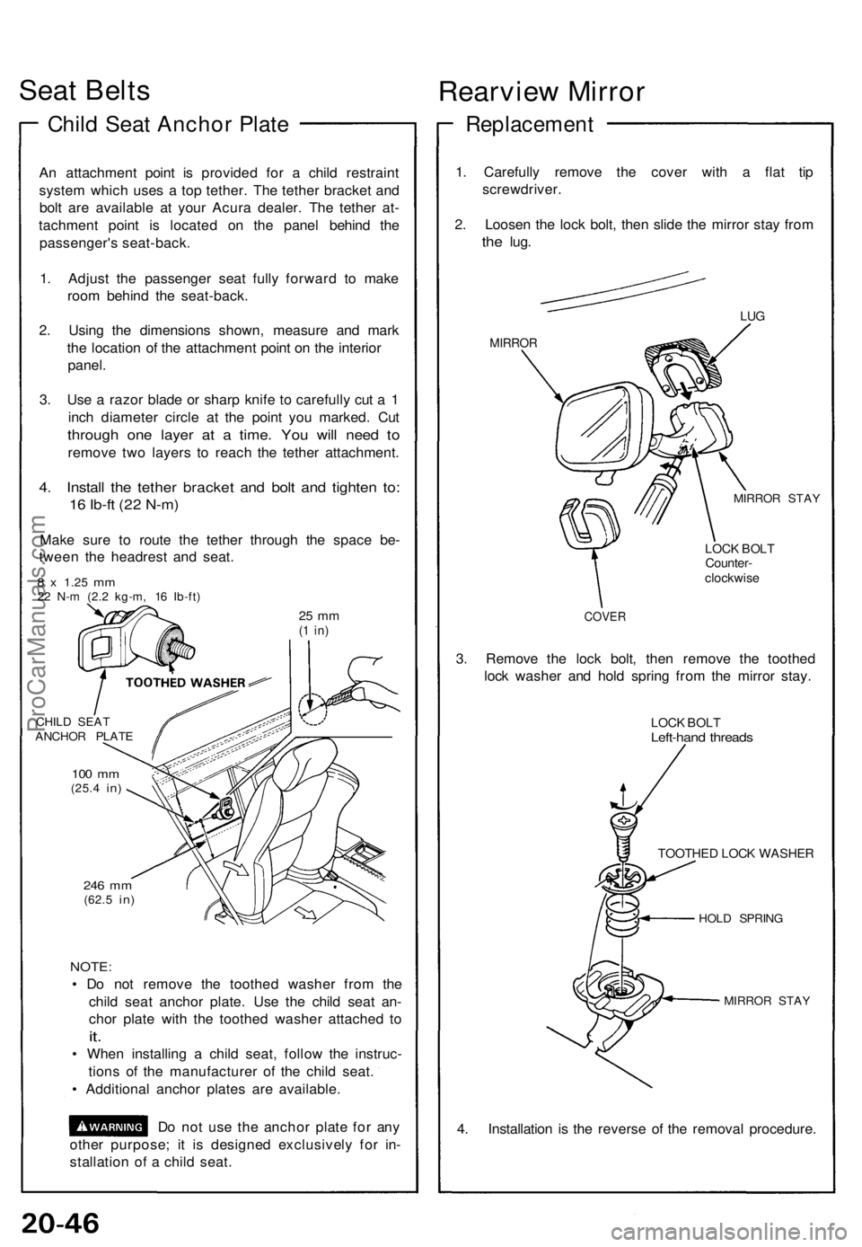
Seat Belt s
Child Sea t Ancho r Plat e
An attachmen t poin t i s provide d fo r a chil d restrain t
syste m whic h use s a to p tether . Th e tethe r bracke t an d
bol t ar e availabl e a t you r Acur a dealer . Th e tethe r at -
tachmen t poin t i s locate d o n th e pane l behin d th e
passenger' s seat-back .
1 . Adjus t th e passenge r sea t full y forwar d t o mak e
roo m behin d th e seat-back .
2 . Usin g th e dimension s shown , measur e an d mar k
th e locatio n o f th e attachmen t poin t o n th e interio r
panel .
3 . Us e a razo r blad e o r shar p knif e t o carefull y cu t a 1
inc h diamete r circl e a t th e poin t yo u marked . Cu t
throug h on e laye r a t a time . Yo u wil l nee d t o
remov e tw o layer s t o reac h th e tethe r attachment .
4. Instal l th e tethe r bracke t an d bol t an d tighte n to :
16 Ib-f t (2 2 N-m )
Make sur e t o rout e th e tethe r throug h th e spac e be -
twee n th e headres t an d seat .
8 x 1.2 5 mm22 N- m (2. 2 kg-m , 1 6 Ib-ft )
25 m m(1 in )
CHIL D SEA T
ANCHO R PLAT E
100 m m(25. 4 in)
246 m m(62. 5 in)
NOTE :
• D o no t remov e th e toothe d washe r fro m th e
chil d sea t ancho r plate . Us e th e chil d sea t an -
cho r plat e wit h th e toothe d washe r attache d t o
it.
• Whe n installin g a chil d seat , follo w th e instruc -
tion s o f th e manufacture r o f th e chil d seat .
• Additiona l ancho r plate s ar e available .
D o no t us e th e ancho r plat e fo r an y
othe r purpose ; i t i s designe d exclusivel y fo r in -
stallatio n o f a chil d seat .
Rearvie w Mirro r
Replacemen t
1. Carefull y remov e th e cove r wit h a fla t ti p
screwdriver .
2 . Loose n th e loc k bolt , the n slid e th e mirro r sta y fro m
the lug .
MIRRO R
LUG
MIRRO R STA Y
LOCK BOL TCounter -
clockwis e
COVER
3. Remov e th e loc k bolt , the n remov e th e toothe d
loc k washe r an d hol d sprin g fro m th e mirro r stay .
LOCK BOL TLeft-han d thread s
TOOTHE D LOC K WASHE R
HOLD SPRIN G
MIRRO R STA Y
4. Installatio n i s th e revers e o f th e remova l procedure .
ProCarManuals.com
Page 607 of 1640
Dashboard
Component Removal/Installation
Clock and center air vent removal:
NOTE: Take care not to scratch the dashboard and
related parts.
1. Remove the clock by pulling it backward from the
center air vent, then disconnect the connector.
2. Remove the center air vent mounting screws.
4. To make a gap between the center air vent and
dashboard, pull the top of the center air vent while
lowering it as shown.
CLOCK
Disconnect the connector.
CENTER AIR
VENT
CENTER AIR VENT
MOUNTING SCREWS
3. Insert a plastic between the center air vent and
center console panel to prevent damaging them.
CENTER AIR VENT
CENTER CONSOLE
PANEL
PLASTIC PLATE
(Thin plate)
NOTE: Make as large a gap as possible.
DASHBOARD
CENTER AIR
VENT
PLASTIC
PLATE
5. Insert a flat tip screwdriver between the center air
vent and dashboard as shown.
NOTE: Use the correct size flat tip screwdriver as
shown.
3.3 mm
(0.13
in)
max.
CENTER AIR
VENT
DASHBOARD
PLASTIC
PLATE
HOOKS
FLAT TIP
SCREWDRIVERProCarManuals.com
Page 608 of 1640
6. After insertting the screwdriver, turn it 90°.
CENTER AIR
VENT
30 mm
(1.2
in)
FLAT TIP
SCREWDRIVER
7. Insert the tip the screwdriver in under the hook by
pivoting it. Detach the hook by prying it.
HOOK
CENTER AIR
VENT
FLAT TIP
SCREWDRIVER
8. Pull the center air vent backward while prying the
hook.
CAUTION: Use a shop towel on the dashboard to
prevent damage.
HOOK
DASHBOARD
CENTER AIR
VENT
SHOP TOWEL
FLAT TIP SCREWDRIVER
9. Detach the other hook in the same manner, then
remove the center air vent.
CENTER AIR
VENT
HOOKS
10. Install the center air vent and clock.
NOTE:
• If there is a minor dent on the dashboard, repair
it by hand as shown.
DASHBOARD
Make sure the connector of the clock is con-
nected properly.
HOOKProCarManuals.com
Page 609 of 1640
Dashboard
Component Removal/Installation (cont'd)
SRS components are located in this area. Review the SRS component locations, precautions, and procedures in the SRS
section (24) before performing repairs or service.
Center console panel removal:
NOTE:
Take cere not to scratch the dashboard, center console panel and related parts.Do not drop the screws inside the dashboard.
Remove the center armrest (see page 20-49('94-'96) ('91-'93)), clock and center air vent (see page 20-50 ('94-'96) ('91-'93)).
Disassemble in numbered sequence.
ASHTRAY
CENTER CONSOLE
PANEL
Disconnect the
connectors.
Lift up the parking
brake lever.
SRS UNIT
Installation is the reverse of the removal procedure. NOTE: Make sure the connectors are connected properly.ProCarManuals.com