Page 1032 of 1640

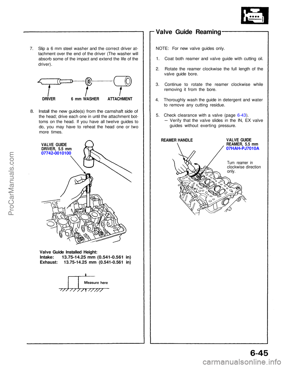
7. Slip a 6 mm steel washer and the correct driver at-
tachment over the end of the driver (The washer willabsorb some of the impact and extend the life of the
driver).
DRIVER 6 mm WASHER ATTACHMENT
8. Install the new guide(s) from the camshaft side of
the head; drive each one in until the attachment bot-
toms on the head. If you have all twelve guides todo, you may have to reheat the head one or twomore times.
VALVE GUIDEDRIVER, 5.5 mm
07742-0010100
Valve Guide Installed Height:
Intake: 13.75-14.25 mm (0.541-0.561 in)
Exhaust: 13.75-14.25 mm (0.541-0.561 in) Valve Guide Reaming
NOTE: For new valve guides only.
1. Coat both reamer and valve guide with cutting oil.
2. Rotate the reamer clockwise the full length of the valve guide bore.
3. Continue to rotate the reamer clockwise while removing it from the bore.
4. Thoroughly wash the guide in detergent and water to remove any cutting residue.
5. Check clearance with a valve (page 6-43).
REAMER HANDLE VALVE GUIDE
REAMER, 5.5 mm
07HAH-PJ7010A
Turn reamer in
clockwise direction
only.
Verify that the valve slides in the IN, EX valve
guides without exerting pressure.ProCarManuals.com
Page 1033 of 1640

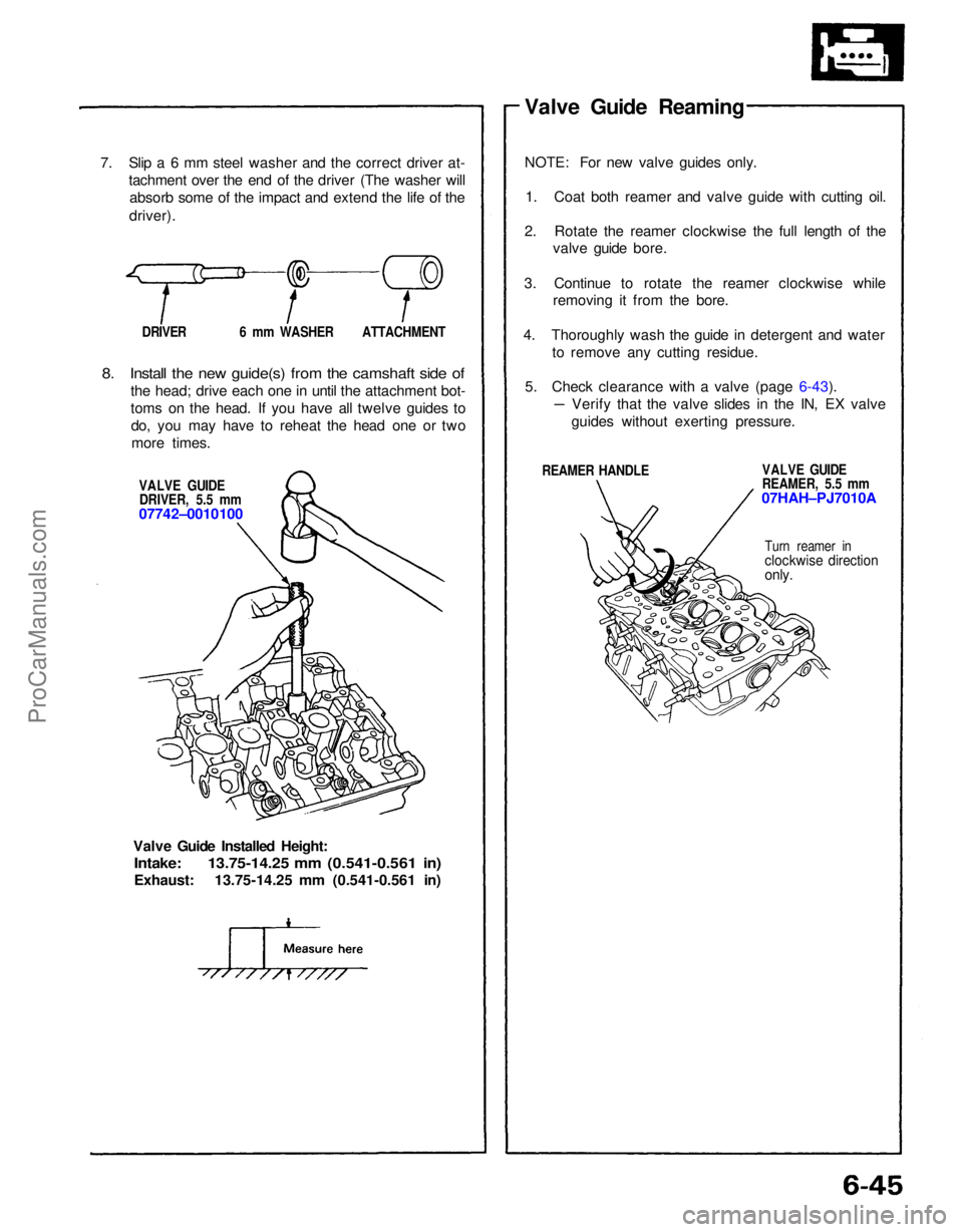
7. Slip a 6 mm steel washer and the correct driver at-
tachment over the end of the driver (The washer willabsorb some of the impact and extend the life of the
driver).
DRIVER 6 mm WASHER ATTACHMENT
8. Install the new guide(s) from the camshaft side of
the head; drive each one in until the attachment bot-
toms on the head. If you have all twelve guides todo, you may have to reheat the head one or twomore times.
VALVE GUIDEDRIVER, 5.5 mm
07742–0010100
Valve Guide Installed Height:
Intake: 13.75-14.25 mm (0.541-0.561 in)
Exhaust: 13.75-14.25 mm (0.541-0.561 in) Valve Guide Reaming
NOTE: For new valve guides only.
1. Coat both reamer and valve guide with cutting oil.
2. Rotate the reamer clockwise the full length of the valve guide bore.
3. Continue to rotate the reamer clockwise while removing it from the bore.
4. Thoroughly wash the guide in detergent and water to remove any cutting residue.
5. Check clearance with a valve (page 6-43).
REAMER HANDLE VALVE GUIDE
REAMER, 5.5 mm
07HAH–PJ7010A
Turn reamer in
clockwise direction
only.
Verify that the valve slides in the IN, EX valve
guides without exerting pressure.ProCarManuals.com
Page 1041 of 1640
Valve Clearance
Adjustment
Valves should be adjusted cold when the cylinder head
temperature is less than 100°F (38°C).
Adjustment is the same for both intake and exhaust
valves.
Adjust valve clearance at TDC of each cylinder.
Do not rotate the engine counterclockwise. The tim-
ing belt could jump a tooth on the camshaft pulleys.
EXHAUST
INTAKE
INTAKE
EXHAUST
TDC MARK (WHITE PAINT)
CRANKSHAFT PULLEY
POINTER ON
THE LOWER
COVER
TDC mark (white paint) on the crank pulley should
align with pointer on the timing lower cover, and
TDC grooves on the camshaft pulleys should align
with timing belt cover plates.
FRONT:
No.1 PISTON at TDC
REAR:
NOTE:
1. Remove the cylinder head covers.
FRONT:
REAR:
2. Rotate crankshaft and set No.1 piston at TDC.ProCarManuals.com
Page 1043 of 1640

Valve Clearance
Adjustment (cont'd)
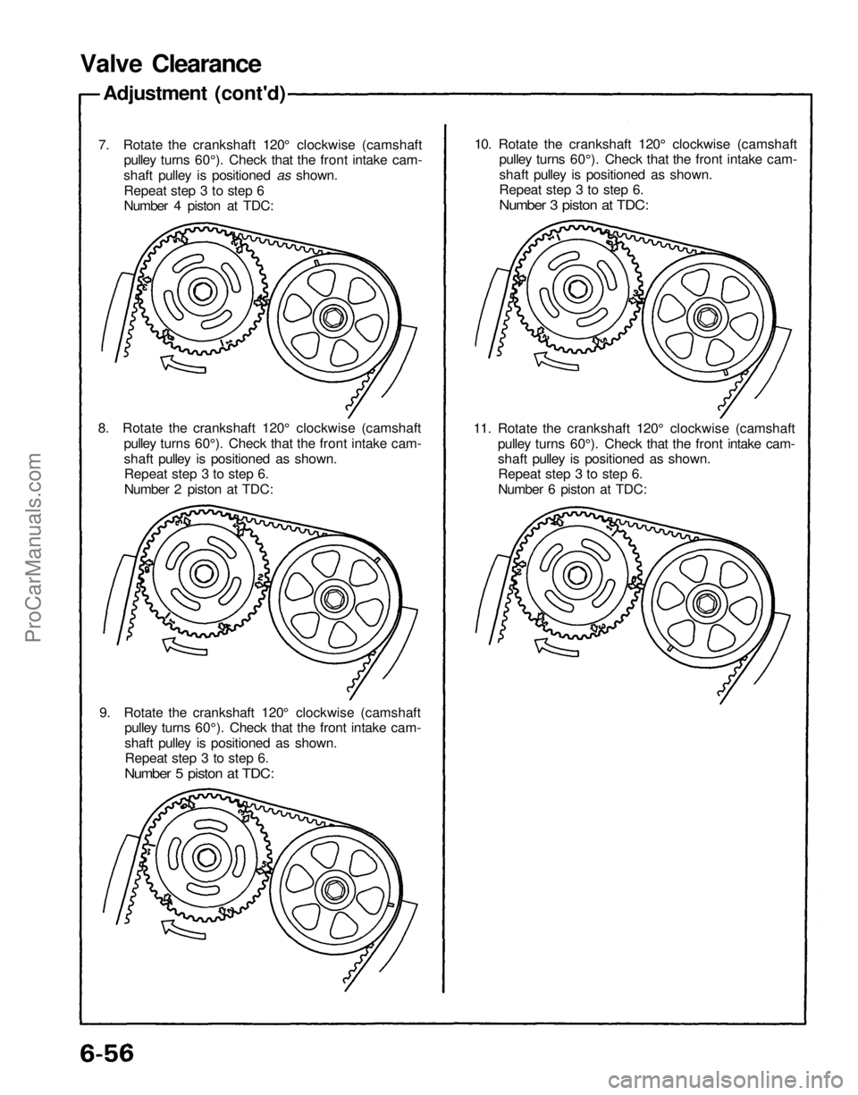
7. Rotate the crankshaft 120° clockwise (camshaft
pulley turns 60°). Check that the front intake cam-
shaft pulley is positioned as shown.
Repeat step 3 to step 6
Number 4 piston at TDC:
8. Rotate the crankshaft 120° clockwise (camshaft
pulley turns 60°). Check that the front intake cam-
shaft pulley is positioned as shown.
Repeat step 3 to step 6.
Number 2 piston at TDC:
9. Rotate the crankshaft 120° clockwise (camshaft
pulley turns 60°). Check that the front intake cam-
shaft pulley is positioned as shown.
Repeat step 3 to step 6.
Number 5 piston at TDC:
11. Rotate the crankshaft 120° clockwise (camshaft
pulley turns 60°). Check that the front intake cam-
shaft pulley is positioned as shown.
Repeat step 3 to step 6.
Number 6 piston at TDC:
10. Rotate the crankshaft 120° clockwise (camshaft
pulley turns 60°). Check that the front intake cam-
shaft pulley is positioned as shown.
Repeat step 3 to step 6.
Number 3 piston at TDC:ProCarManuals.com
Page 1055 of 1640
System Description
Electrical Connections
FUSES
CLOCK (7.5 A)*
ACG
(120 A)**
ACG(S) (20 A)**
IG COIL (30 A)**
No. 2 (15 A)
No. 5 (10 A)
No.
4(15
A)
No. 7
(7.5
A)
In the under-hood
fuse/relay box In the engine
compartment
fuse/relay box
CKP/CYP
SENSOR
TO A/T
GEAR
POSITION
SWITCH
NEUTRAL
SWITCH
(M/T)
AUTO A/C
CONTROL
UNIT
CLUTCH
SWITCH
(M/T)
SERVICE
CHECK
CONNECTOR
A/C
PRESSURE
SWITCH A
A/C
PRESSURE
SWITCH B FUEL PUMP
RESISTORProCarManuals.com
Page 1079 of 1640
II. ENGINE CONTROL MODULE (ECM) Reset Procedure
1. Turn the ignition switch off.
2. Remove the CLOCK (7.5 A) fuse from the under-hood fuse/relay box for 10 seconds to reset ECM.
NOTE: Disconnecting the CLOCK fuse also cancels the radio preset stations and the clock setting. Make note of
the radio presets before removing the fuse so you can reset them.
III. Final Procedure (this procedure must be done after any troubleshooting)
1. Remove the Jumper Wire.
NOTE: If the Service Check Connector is jumped, the MIL will stay on.
2. Do the ECM Reset Procedure.
3. Set the radio preset stations and the clock setting.
(cont'd)
CLOCK
(7.5 A) FUSE
UNDER-HOOD
FUSE/RELAY BOXProCarManuals.com
Page 1106 of 1640

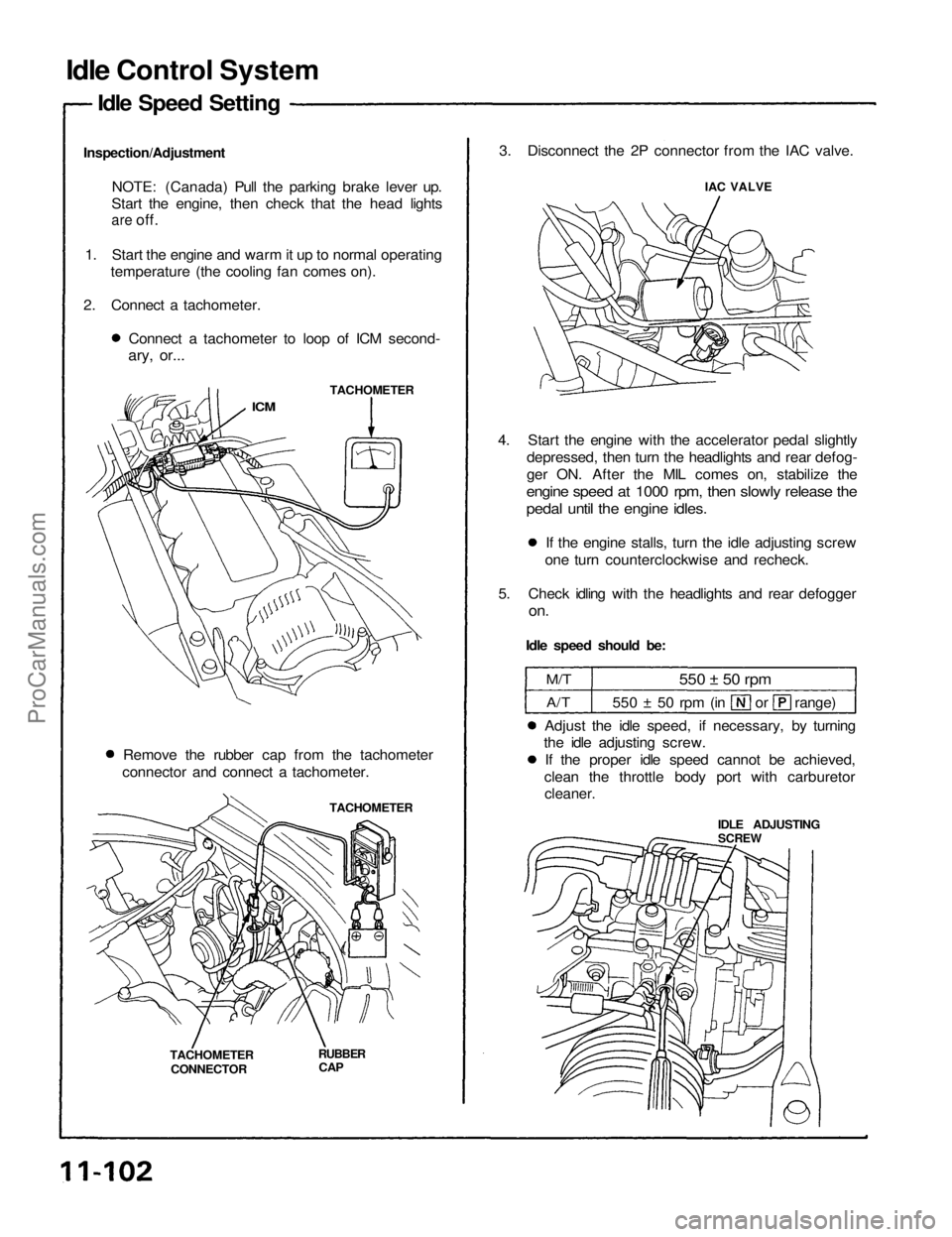
Idle Control System
Idle Speed Setting
Inspection/Adjustment NOTE: (Canada) Pull the parking brake lever up.
Start the engine, then check that the head lights
are
off.
1. Start the engine and warm it up to normal operating temperature (the cooling fan comes on).
2. Connect a tachometer. Connect a tachometer to loop of ICM second-
ary, or...
TACHOMETER
ICM
Remove the rubber cap from the tachometer
connector and connect a tachometer.
TACHOMETER
TACHOMETER CONNECTOR
RUBBER
CAP
3. Disconnect the 2P connector from the IAC valve.
IAC VALVE
4. Start the engine with the accelerator pedal slightly depressed, then turn the headlights and rear defog-
ger ON. After the MIL comes on, stabilize the
engine speed at 1000 rpm, then slowly release the
pedal until the engine idles.
If the engine stalls, turn the idle adjusting screw
one turn counterclockwise and recheck.
5. Check idling with the headlights and rear defogger
on.
Idle speed should be:
M/T
A/T
550 ± 50 rpm
550 ± 50 rpm (in or range)
Adjust the idle speed, if necessary, by turning
the idle adjusting screw.
If the proper idle speed cannot be achieved,
clean the throttle body port with carburetor
cleaner.
IDLE ADJUSTING
SCREWProCarManuals.com
Page 1107 of 1640
6. Turn the ignition switch OFF.
7. Reconnect the 2P connector on the IAC valve, then
remove CLOCK fuse in the under-hood fuse/relay
box for 10 seconds to reset ECM.
8. Restart and idle the engine with no-load conditions
in which the headlights, blower fan, rear defogger,
cooling fan, and air conditioner are not operating
for one minute, then check the idle speed.
Idle speed should be:
M/T
A/T
800
50 rpm
750
50 rpm
(in or range)ProCarManuals.com