1991 ACURA NSX clock
[x] Cancel search: clockPage 270 of 1640
Intake Ai r Syste m
Throttl e Cabl e
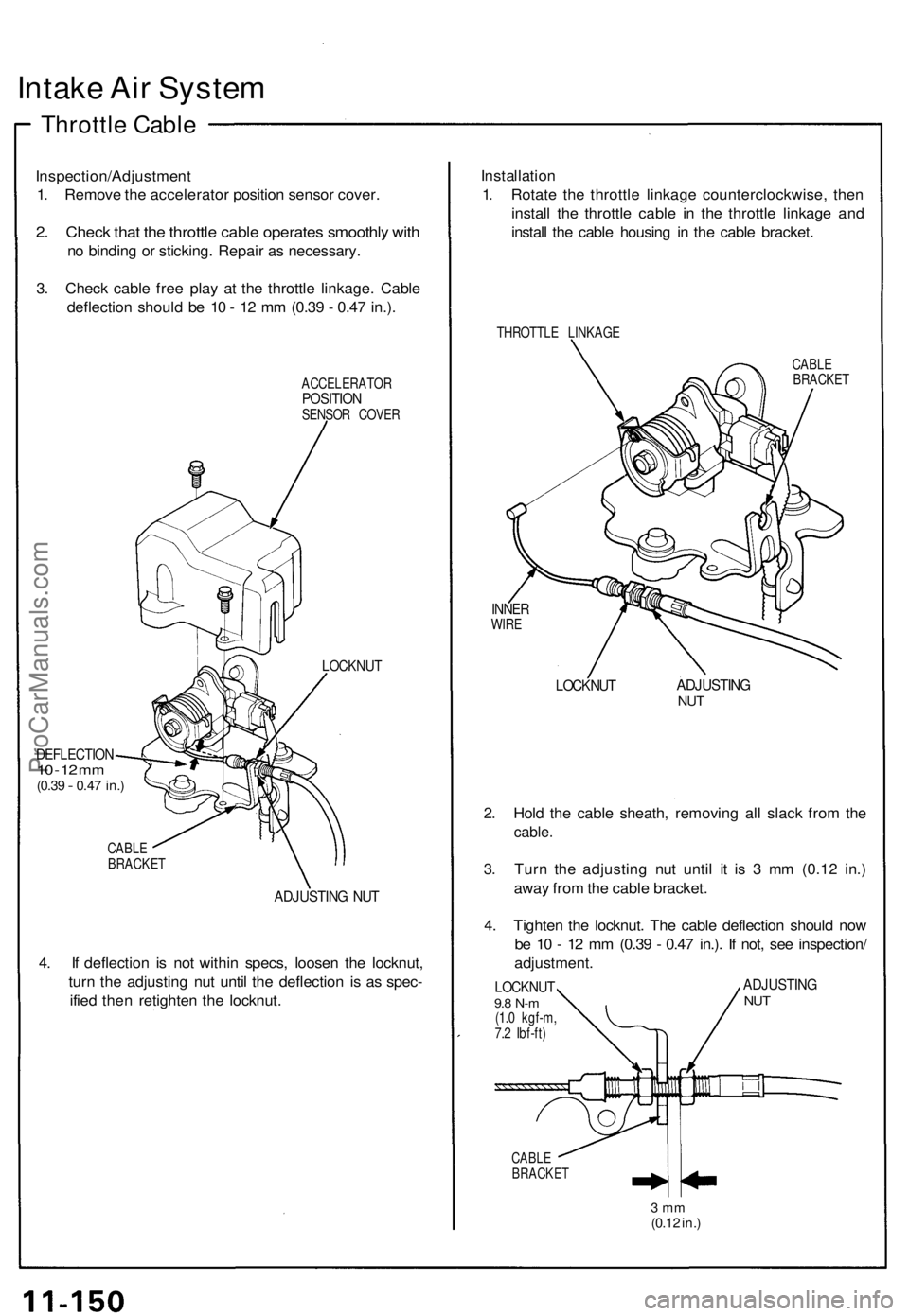
Inspection/Adjustmen t
1 . Remov e th e accelerato r positio n senso r cover .
2. Chec k tha t th e throttl e cabl e operate s smoothl y wit h
no bindin g o r sticking . Repai r a s necessary .
3 . Chec k cabl e fre e pla y a t th e throttl e linkage . Cabl e
deflectio n shoul d b e 1 0 - 1 2 m m (0.3 9 - 0.4 7 in.) .
ACCELERATO RPOSITIONSENSOR COVE R
DEFLECTIO N10 - 1 2 m m(0.3 9 - 0.47 in. )
LOCKNU T
CABLE
BRACKE T
ADJUSTIN G NU T
4. I f deflectio n i s no t withi n specs , loose n th e locknut ,
tur n th e adjustin g nu t unti l th e deflectio n i s a s spec -
ifie d the n retighte n th e locknut . Installatio
n
1 . Rotat e th e throttl e linkag e counterclockwise , the n
instal l th e throttl e cabl e i n th e throttl e linkag e an d
instal l th e cabl e housin g i n th e cabl e bracket .
THROTTL E LINKAG E
CABLE
BRACKE T
INNERWIRE
LOCKNU TADJUSTIN GNUT
2. Hol d th e cabl e sheath , removin g al l slac k fro m th e
cable .
3. Tur n th e adjustin g nu t unti l i t i s 3 m m (0.1 2 in. )
awa y fro m th e cabl e bracket .
4 . Tighte n th e locknut . Th e cabl e deflectio n shoul d no w
b e 1 0 - 1 2 m m (0.3 9 - 0.4 7 in.) . I f not , se e inspection /
adjustment .
LOCKNUT9.8 N- m(1.0 kgf-m ,
7. 2 Ibf-ft )
ADJUSTIN GNUT
CABL EBRACKE T
3 m m(0.1 2 in. )
ProCarManuals.com
Page 346 of 1640
Mainshaft Thrus t Shi m
Adjustmen t
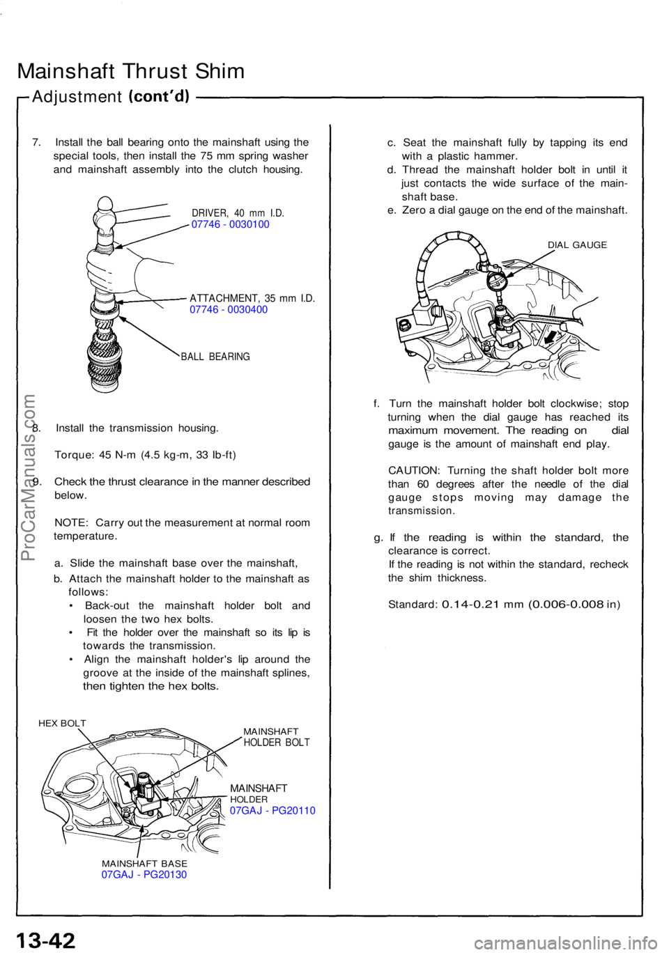
7. Instal l th e bal l bearin g ont o th e mainshaf t usin g th e
specia l tools , the n instal l th e 7 5 m m sprin g washe r
an d mainshaf t assembl y int o th e clutc h housing .
DRIVER, 4 0 m m I.D .07746 - 0030100
ATTACHMENT , 3 5 m m I.D .07746 - 0030400
BAL L BEARIN G
8. Instal l th e transmissio n housing .
Torque : 4 5 N- m (4. 5 kg-m , 3 3 Ib-ft )
9. Chec k th e thrus t clearanc e in th e manne r describe d
below.
NOTE : Carr y ou t th e measuremen t a t norma l roo m
temperature .
a . Slid e th e mainshaf t bas e ove r th e mainshaft ,
b . Attac h th e mainshaf t holde r t o th e mainshaf t a s
follows :
• Back-ou t th e mainshaf t holde r bol t an d
loose n th e tw o he x bolts .
• Fi t th e holde r ove r th e mainshaf t s o it s li p i s
toward s th e transmission .
• Alig n th e mainshaf t holder' s li p aroun d th e
groov e a t th e insid e of the mainshaf t splines ,
then tighte n th e he x bolts .
HEX BOL T
MAINSHAFT
HOLDER BOL T
MAINSHAF THOLDER07GAJ - PG20110
MAINSHAF T BAS E07GAJ - PG20130
c. Sea t th e mainshaf t full y b y tappin g it s en d
wit h a plasti c hammer .
d . Threa d th e mainshaf t holde r bol t i n unti l i t
jus t contact s th e wid e surfac e o f th e main -
shaf t base .
e . Zer o a dia l gaug e o n th e en d o f th e mainshaft .
DIAL GAUG E
f. Tur n th e mainshaf t holde r bol t clockwise ; sto p
turnin g whe n th e dia l gaug e ha s reache d it s
maximu m movement . Th e readin g o n dia l
gauge i s th e amoun t o f mainshaf t en d play .
CAUTION : Turnin g th e shaf t holde r bol t mor e
tha n 6 0 degree s afte r th e needl e o f th e dia l
gaug e stop s movin g ma y damag e th e
transmission .
g. I f th e readin g i s withi n th e standard , th e
clearanc e is correct .
I f th e readin g i s no t withi n th e standard , rechec k
th e shi m thickness .
Standard :
0.14-0.21 mm (0.006-0.00 8 in)
ProCarManuals.com
Page 358 of 1640

Preset Torqu e
Inspectio n
On-Car:
1 . Bloc k th e fron t wheels .
2 . Shif t t o low gear .
3 . Lif t u p rea r wheels , an d plac e th e safet y stan d (Lif t
an d Suppor t Points , se e sectio n 1 ).
4 . Measur e prese t torqu e clockwis e usin g a torqu e
wrenc h a s shown .
Standard: 120-280 N-m (12-28 kg-m,
87-20 3 Ib-ft )
Servic e Limit : 6 0 N- m (6 kg-m , 4 3 Ib-ft )
TORQU E WRENC H
RIGH T REA R WHEE L
SAFETY STAN D
5. I f prese t torqu e is les s tha n th e servic e limit , replac e
th e limite d sli p differentia l clutc h set .
NOTE : Adjus t th e 6 5 m m (differentia l housin g cove r
side ) an d 11 2 m m (differentia l housin g cove r side )
shim s wheneve r th e clutc h se t i s replaced . Assembly
:
Plac e on e specia l too l i n a vise . Plac e th e lef t sid e
o f th e differentia l assembl y o n th e specia l tool , the n
prese t th e differentia l wit h 3- 5 rotations , counter -
clockwise .
DIFFERENTIA L
INSPECTIO N TOOL S
07MAJ-PR90100
2. Measur e prese t torqu e counterclockwis e usin g a tor -
qu e wrenc h a s shown.
Standard :
60-140 N- m (6-1 4 kg-m ,
43-10 1 Ib-ft )
Servic e Limit : 3 0 N- m (3 kg-m , 2 2 Ib-ft )
TORQU E WRENC H
DIFFERENTIA L
INSPECTIO N TOOL S
07MAJ-PR90100
3 . I f prese t torqu e is les s tha n th e servic e limit , replac e
th e limite d sli p differentia l clutc h set .
NOTE : Adjus t th e 6 5 m m an d 11 2 m m shim s
wheneve r th e clutc h se t i s replaced .
ProCarManuals.com
Page 373 of 1640
Preset Torque
Inspection
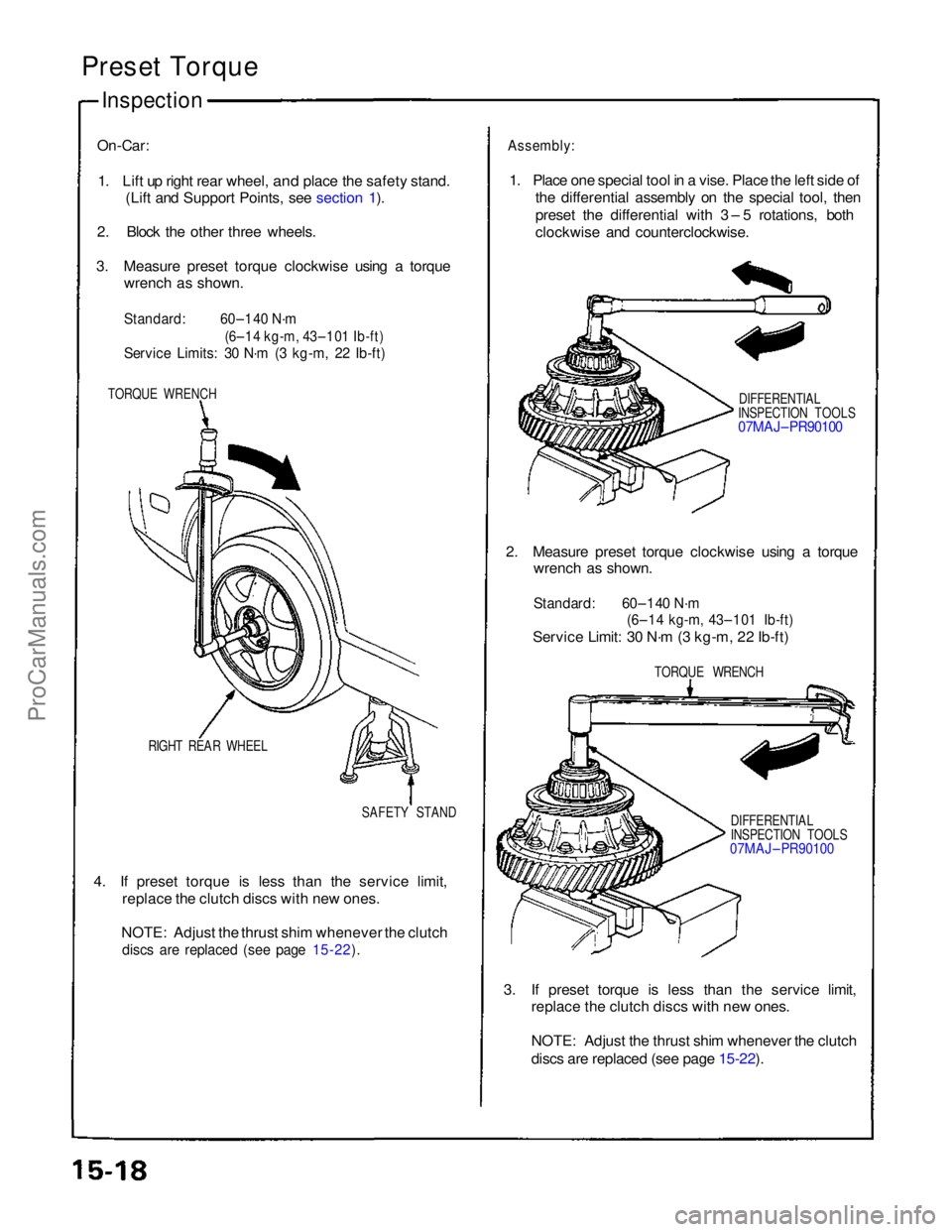
On-Car:
1. Lift up right rear wheel,
and place the safety stand.
(Lift and Support Points, see section 1).
2. Block the other three wheels.
3. Measure preset torque clockwise using a torque wrench as shown.
Standard:
60–140 N·m
(6–14 kg-m, 43–101 Ib-ft)
Service Limits: 30 N·m (3 kg-m, 22 Ib-ft)
TORQUE WRENCH
RIGHT REAR WHEEL SAFETY STAND
4. If preset torque is less than the service limit, replace the clutch discs with new ones.
NOTE: Adjust the thrust shim whenever the clutch
discs are replaced (see page 15-22).
Assembly:
1. Place one special tool in a vise. Place the left side of the differential assembly on the special tool, then
preset the differential with 3 – 5 rotations, both
clockwise and counterclockwise.
DIFFERENTIAL
INSPECTION TOOLS
07MAJ– PR90100
2. Measure preset torque clockwise using a torque wrench as shown.
Standard: 60–140 N·m
(6–14 kg-m, 43–101 Ib-ft)
Service Limit: 30 N·m (3 kg-m, 22 Ib-ft)
TORQUE WRENCH
DIFFERENTIAL
INSPECTION TOOLS
07MAJ – PR90100
3. If preset torque is less than the service limit, replace the clutch discs with new ones.
NOTE: Adjust the thrust shim whenever the clutch
discs are replaced (see page 15-22).
ProCarManuals.com
Page 417 of 1640
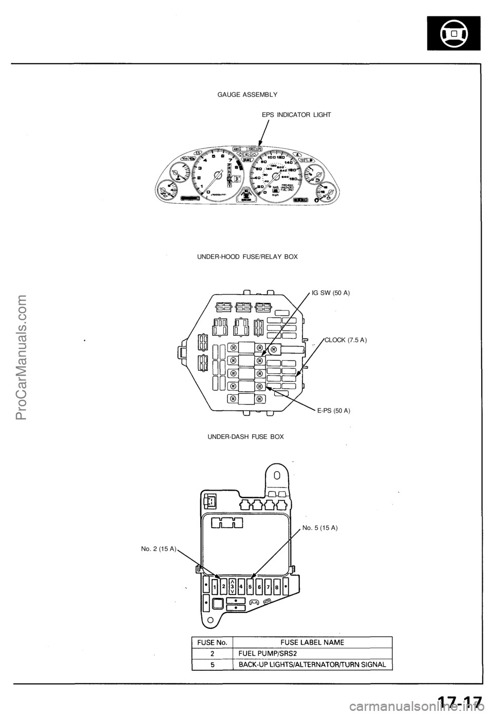
GAUGE ASSEMBLY
EPS INDICATOR LIGHT
UNDER-HOOD FUSE/RELAY BOX
No. 2 (15 A)
IG SW (50 A)
CLOCK (7.5 A)
E-PS
(50 A)
UNDER-DASH FUSE BOX
No. 5 (15 A)ProCarManuals.com
Page 420 of 1640
Troubleshooting Precautions
EPS Indicator Light
Under normal conditions, the EPS indicator light in the gauge assembly comes on when the ignition switch is turned to
the ON (II) position, then goes off after the engine is started. This indicates that the bulb and its circuits are operating cor-
rectly. If there is any trouble in the system, the EPS indicator light turns on during driving, and the power steering assist is
turned off. When the EPS indicator light comes on, the control unit memorizes the DTC. In this case, the control unit does
not activate the EPS system after the engine starts again but it keeps the EPS indicator light on.
Diagnostic Trouble Code (DTC)
• The lowest DTC is indicated first.
• The DTCs continue blinking until the ignition switch is turned off.
• The DTCs are erased from the control unit when the EPS control unit VBU power supply or connector is disconnected.
• The EPS system can be reset and the control unit's memory can be erased by disconnecting the CLOCK (7.5 A) fuse for
more than ten seconds.
Self-diagnosis:
The CPU (central processing unit) controls the following when it detects a problem during self-diagnosis:
1. Turns the EPS indicator light ON to alert the driver.
2. Power assist stops, and normal manual steering operation resumes (except DTC 21 and DTC 33).
3. The EPS control unit memorizes the diagnostic trouble code (DTC).
4. After the DTC is stored in the control unit, the CPU stops self-diagnosis.
Troubleshooting:
• Before starting the troubleshooting, clear the DTC by disconnecting the CLOCK (7.5 A) fuse for ten seconds or more,
and test-drive the car. Check that the symptom of the trouble appears again, and then troubleshoot. If the problem is an
intermittent problem, the system does not become active after the engine starts even though the problem is solved.
• When both EPS indicator light and A/T "D" indicator light come on, perform the A/T troubleshooting first.
• When the customer's reported problem cannot be verified in the car, ask the customer about the conditions when the
EPS indicator light came ON, then test-drive the car under those conditions, if possible. If the EPS indicator light does
not come ON during the test, check for loose connections or poor contacts at the connectors by wiggling the harness,
etc.
• The connector terminal numbers are viewed from the wire side for the female terminals and from the terminal side for
the male terminals.
• After the repair, test-drive the car and check that the EPS indicator light does not come ON again during the test. (Refer
to the Symptom-to-System Chart for diagnostic period.)ProCarManuals.com
Page 422 of 1640
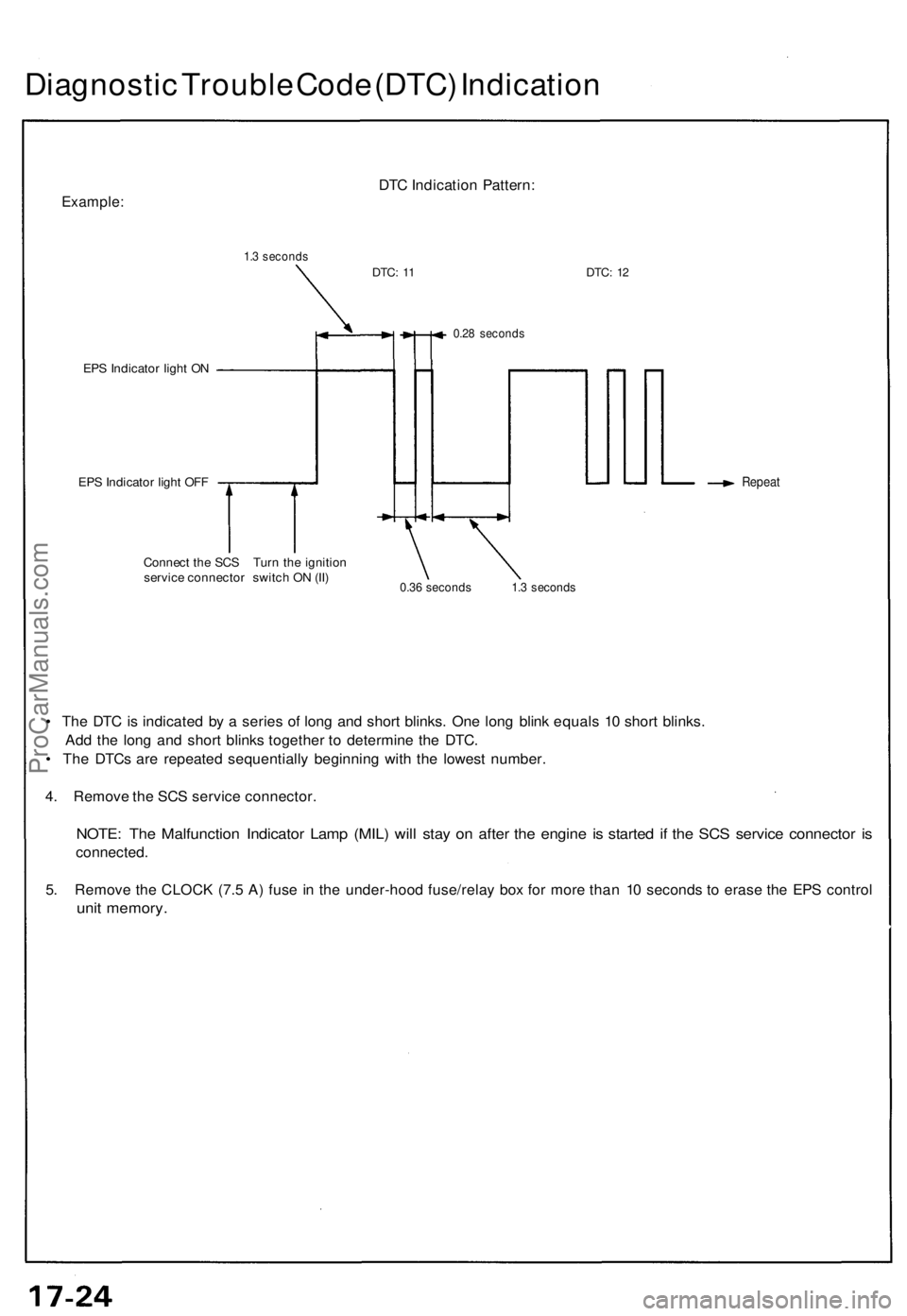
Diagnostic Trouble Code (DTC) Indication
Example:
1.3 seconds
DTC Indication Pattern:
DTC:
11
DTC:
12
EPS Indicator light ON
EPS Indicator light OFF
0.28 seconds
Repeat
Connect the SCS Turn the ignition
service connector switch ON (II)
0.36 seconds 1.3 seconds
• The DTC is indicated by a series of long and short blinks. One long blink equals 10 short blinks.
Add the long and short blinks together to determine the DTC.
• The DTCs are repeated sequentially beginning with the lowest number.
4. Remove the SCS service connector.
NOTE: The Malfunction Indicator Lamp (MIL) will stay on after the engine is started if the SCS service connector is
connected.
5. Remove the CLOCK (7.5 A) fuse in the under-hood fuse/relay box for more than 10 seconds to erase the EPS control
unit memory.ProCarManuals.com
Page 429 of 1640
Installation
NOTE: Before installing the steering wheel, make sure
the front wheels are straight ahead.
CAUTION:
• Be sure to install the harness wires so that they are
not pinched or interfering with other car parts.
• Do not replace the original steering wheel with any
other design, since it will make it impossible to prop-
erly install the airbag. (Use only genuine Honda
replacement parts.)
• After reassembly, confirm that the wheels are still
straight ahead and that steering wheel spoke angle
is correct. If minor spoke angle adjustment is neces-
sary, adjust the tie-rods only. Do not remove and
reposition the steering wheel.
Confirm that the airbag assembly is securely
attached to the steering wheel; otherwise, severe per-
sonal injury could result during later airbag deploy-
ment.
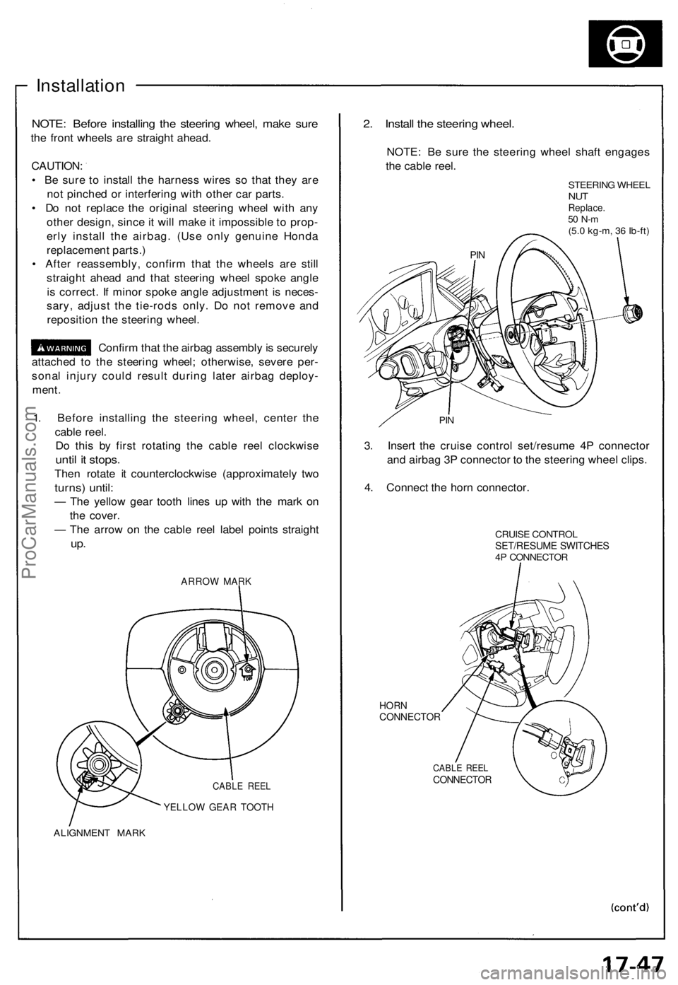
1. Before installing the steering wheel, center the
cable reel.
Do this by first rotating the cable reel clockwise
until it stops.
Then rotate it counterclockwise (approximately two
turns) until:
— The yellow gear tooth lines up with the mark on
the cover.
— The arrow on the cable reel label points straight
up.
ARROW MARK
CABLE REEL
YELLOW GEAR TOOTH
ALIGNMENT MARK
2. Install the steering wheel.
NOTE: Be sure the steering wheel shaft engages
the cable reel.
STEERING WHEEL
NUT
Replace.
50 N-m
(5.0 kg-m, 36 Ib-ft)
PIN
3. Insert the cruise control set/resume 4P connector
and airbag 3P connector to the steering wheel clips.
4. Connect the horn connector.
CRUISE CONTROL
SET/RESUME SWITCHES
4P CONNECTOR
HORN
CONNECTOR
CABLE REEL
CONNECTOR
PINProCarManuals.com