Page 1376 of 1640
Dashboard
Component Removal/Installation (cont'd)
SRS wire harnesses are routed near the dashboard. CAUTION:
LEFT DASH
SENSOR PASSENGER'S
AIRBAG
RIGHT DASH
SENSOR
SRS MAIN
HARNESS
SRS UNIT
Center console panel removal:
NOTE:
Disassemble in numbered sequence.
ASHTRAY
CENTER CONSOLE PANEL
Disconnect the
connectors.
SRS
UNIT
Lift up the parking
brake lever.
Installation is the reverse of the removal procedure. NOTE: Make sure the connectors are connected properly.All SRS wiring harnesses are covered with
yellow outer insulation.
Before disconnecting any part of the SRS wire
harness, install the short connectors (see page
23-328).
Replace the entire affected SRS harness assem-
bly if it has an open circuit or damaged wiring.
Take care not to scratch the dashboard, center console panel and related parts.Do not drop the screws inside the dashboard.
Remove the center armrest (see page 20-49), clock and center air vent (see page 20-50).ProCarManuals.com
Page 1379 of 1640
Replacement
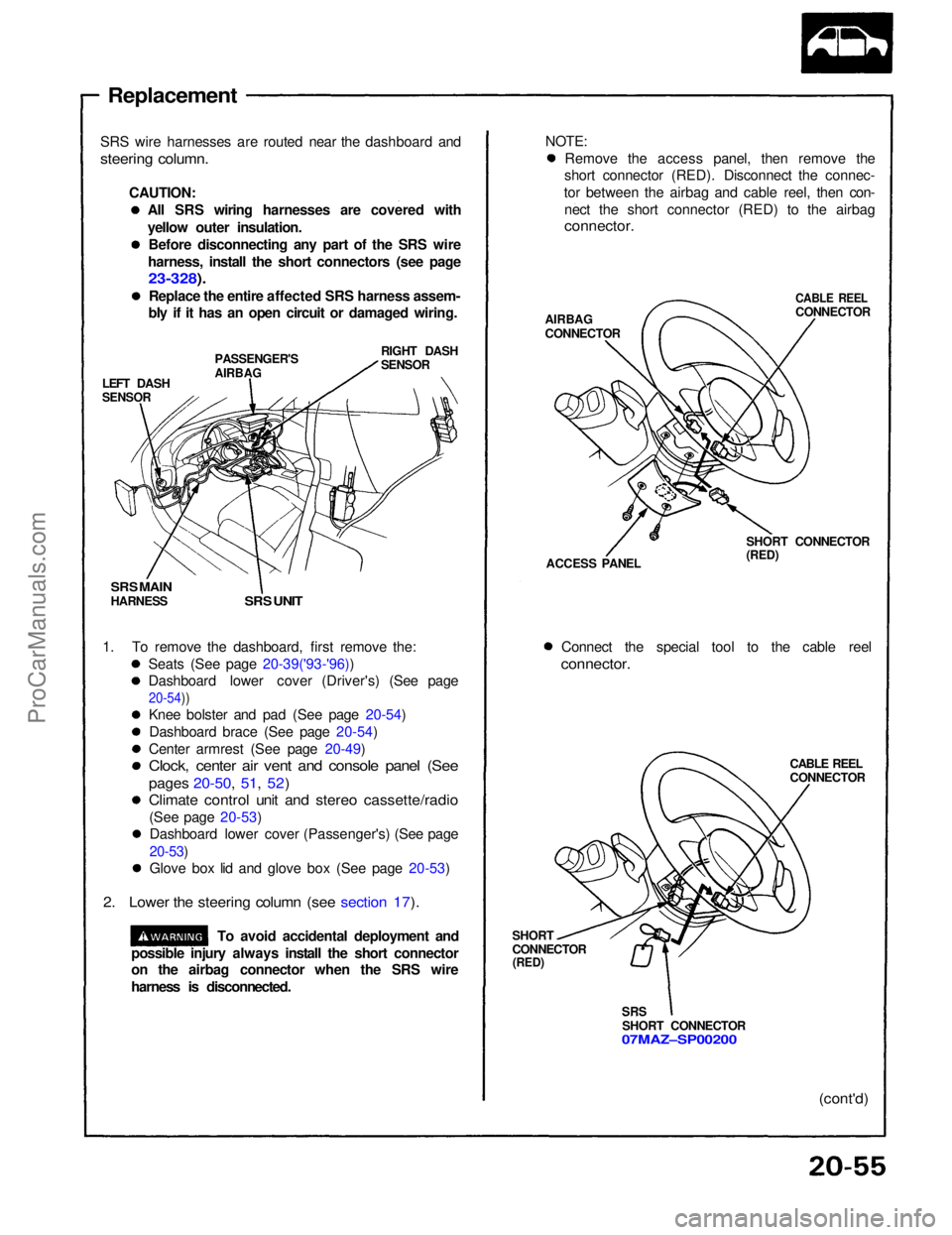
SRS wire harnesses are routed near the dashboard and
steering column.
CAUTION:All SRS wiring harnesses are covered with
yellow outer insulation.Before disconnecting any part of the SRS wire
harness, install the short connectors (see page
23-328).
Replace the entire affected SRS harness assem-
bly if it has an open circuit or damaged wiring.
LEFT DASH
SENSOR
PASSENGER'S
AIRBAG
RIGHT DASH
SENSOR
SRS MAIN
HARNESS
SRS UNIT
1. To remove the dashboard, first remove the: Seats (See page 20-39('93-'96))
Dashboard lower cover (Driver's) (See page
20-54))
Knee bolster and pad (See page 20-54)
Dashboard brace (See page 20-54)
Center armrest (See page 20-49)
Clock, center air vent and console panel (See
pages 20-50, 51, 52)
Climate control unit and stereo cassette/radio
(See page 20-53)Dashboard lower cover (Passenger's) (See page
20-53)
Glove box lid and glove box (See page 20-53)
2. Lower the steering column (see section 17).
To avoid accidental deployment and NOTE:
Remove the access panel, then remove the
short connector (RED). Disconnect the connec-
tor between the airbag and cable reel, then con- nect the short connector (RED) to the airbag
connector.
AIRBAG
CONNECTOR
CABLE REEL
CONNECTOR
ACCESS PANEL SHORT CONNECTOR
(RED)
Connect the special tool to the cable reel
connector.
CABLE REEL
CONNECTOR
SHORT
CONNECTOR
(RED)
SRS
SHORT CONNECTOR
07MAZ–SP00200
(cont'd)
possible injury always install the short connector
on the airbag connector when the SRS wire
harness is disconnected.ProCarManuals.com
Page 1393 of 1640
Ignition Timing Inspection and Setting
1. Start the engine and allow it to warm up (radiator
fan comes on).
2. Pull out the service check connector located under the middle of the dash. Connector the BLU andGRN/WHT terminals with a jumper wire (see sec-
tion 11).
3. Check the idle speed (see page 23-92).
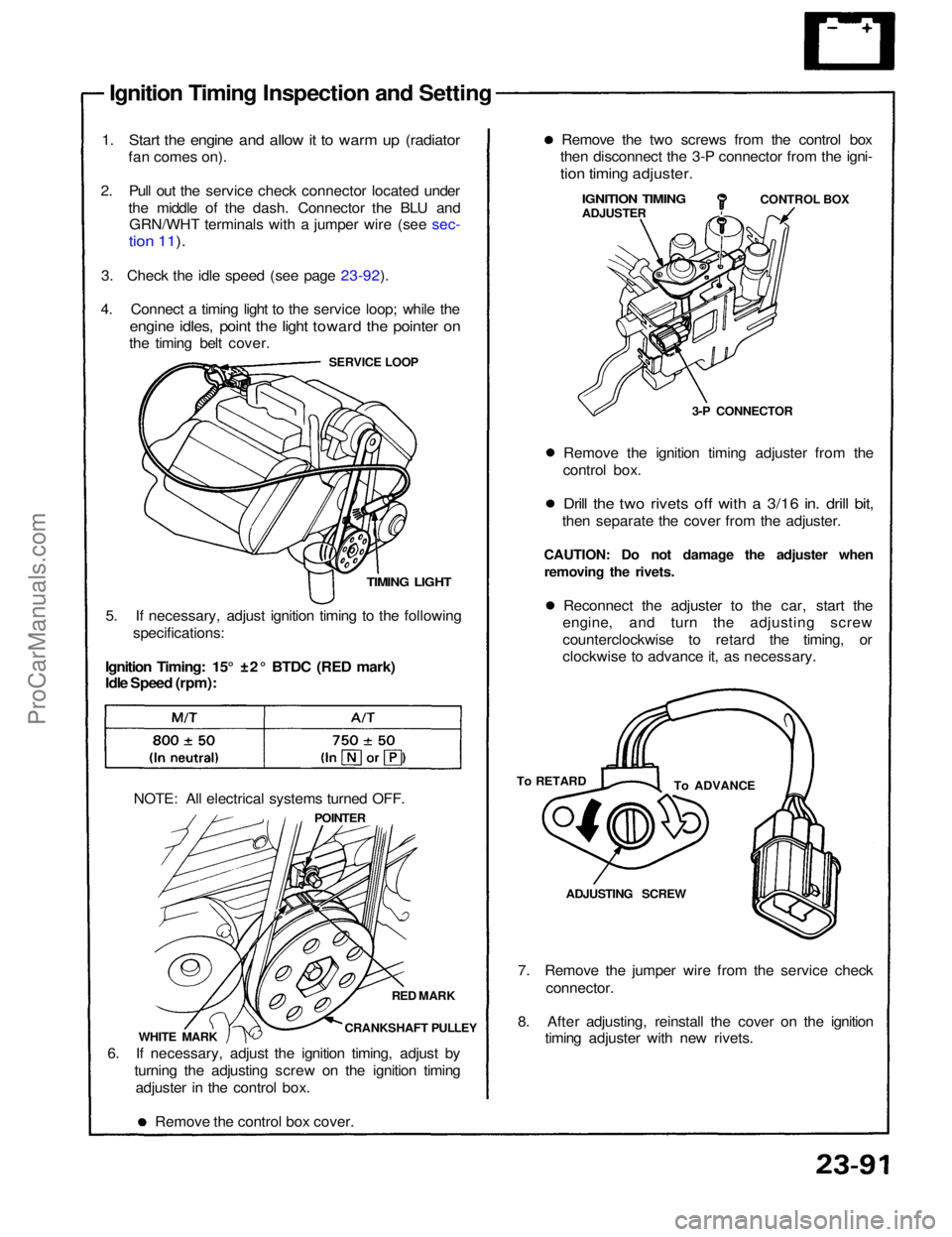
4. Connect a timing light to the service loop; while the
engine idles, point the light toward the pointer on
the timing belt cover.
SERVICE LOOP
TIMING LIGHT
5. If necessary, adjust ignition timing to the following specifications:
Ignition Timing: 15° ±2° BTDC (RED mark)
Idle Speed (rpm):
NOTE: All electrical systems turned OFF. POINTER
RED MARK
CRANKSHAFT PULLEY
WHITE MARK
6. If necessary, adjust the ignition timing, adjust by turning the adjusting screw on the ignition timingadjuster in the control box.
Remove the control box cover. 7. Remove the jumper wire from the service check
connector.
8. After adjusting, reinstall the cover on the ignition timing adjuster with new rivets.ADJUSTING SCREW
To ADVANCE
To RETARD Reconnect the adjuster to the car, start the
engine, and turn the adjusting screw
counterclockwise to retard the timing, or
clockwise to advance it, as necessary.
CAUTION: Do not damage the adjuster when
removing the rivets. Remove the ignition timing adjuster from the
control box.
Drill the two rivets off with a 3/16 in. drill bit,
then separate the cover from the adjuster. 3-P CONNECTORCONTROL BOX
IGNITION TIMING
ADJUSTER
Remove the two screws from the control box
then disconnect the 3-P connector from the igni-
tion timing adjuster.ProCarManuals.com
Page 1440 of 1640
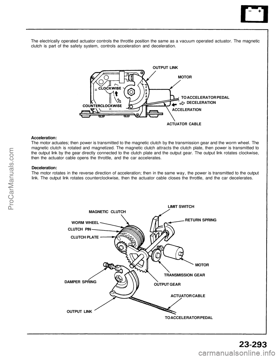
The electrically operated actuator controls the throttle position the same as a vacuum operated actuator. The magnetic
clutch is part of the safety system, controls acceleration and deceleration.
OUTPUT LINK
MOTOR
TO ACCELERATOR PEDAL
DECELERATION
ACCELERATION
ACTUATOR CABLE
Acceleration:
The motor actuates; then power is transmitted to the magnetic clutch by the transmission gear and the worm wheel. The
magnetic clutch is rotated and magnetized. The magnetic clutch attracts the clutch plate, then power is transmitted to
the output link by the gear directly connected to the clutch plate and the output gear. The output link rotates clockwise,
then the actuator cable opens the throttle, and the car accelerates.
Deceleration:
The motor rotates in the reverse direction of acceleration; then in the same way, the power is transmitted to the output
link. The output link rotates counterclockwise, then the actuator cable closes the throttle, and the car decelerates.
LIMIT SWITCH
RETURN SPRING
MOTOR
TRANSMISSION GEAR
OUTPUT GEAR
ACTUATOR CABLE
TO ACCELERATOR PEDAL
OUTPUT LINK
DAMPER SPRING
CLUTCH PLATE
CLUTCH PIN
WORM WHEEL
MAGNETIC CLUTCHProCarManuals.com
Page 1498 of 1640
Idle Control System
Idle Speed Setting
Inspection/Adjustment
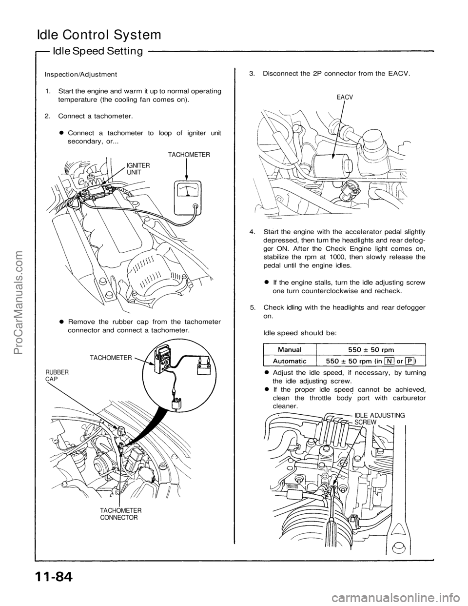
1. Start the engine and warm it up to normal operating temperature (the cooling fan comes on).
2. Connect a tachometer. Connect a tachometer to loop of igniter unit
secondary, or... 3. Disconnect the 2P connector from the EACV.
EACV
TACHOMETER
IGNITER
UNIT
4. Start the engine with the accelerator pedal slightlydepressed, then turn the headlights and rear defog-
ger ON. After the Check Engine light comes on,stabilize the rpm at 1000, then slowly release the
pedal until the engine idles. If the engine stalls, turn the idle adjusting screw
one turn counterclockwise and recheck.
5. Check idling with the headlights and rear defogger
on.
Idle speed should be:
Remove the rubber cap from the tachometer
connector and connect a tachometer.
TACHOMETER
RUBBER
CAP
Adjust the idle speed, if necessary, by turning
the idle adjusting screw. If the proper idle speed cannot be achieved,
clean the throttle body port with carburetor
cleaner.
IDLE ADJUSTING
SCREW
TACHOMETER CONNECTORProCarManuals.com
Page 1499 of 1640
6. Turn the ignition switch OFF.
7. Reconnect the 2P connector on the EACV, then
remove CLOCK fuse in the under-hood fuse/relay
box for 10 seconds to reset ECU.
8. Restart and idle the engine with no-load conditions
in which the headlights, blower fan, rear defogger,
cooling fan, and air conditioner are not operating
for one minute, then check the idle speed.
Idle speed should be:ProCarManuals.com
Page 1580 of 1640
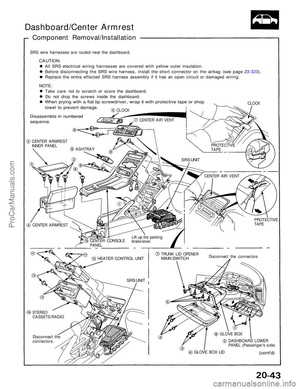
Dashboard/Center Armrest
Component Removal/Installation
SRS wire harnesses are routed near the dashboard.
CAUTION:
All SRS electrical wiring harnesses are covered with yellow outer insulation.Before disconnecting the SRS wire harness, install the short connector on the airbag (see page 23-323). Replace the entire effected SRS harness assembly if it has an open circuit or damaged wiring.
NOTE: Take care not to scratch or score the dashboard.Do not drop the screws inside the dashboard.
When prying with a flat tip screwdriver, wrap it with protective tape or shop
towel to prevent damage.
Disassemble in numbered
sequence.
CLOCK
CLOCK
CENTER AIR VENT
CENTER ARMREST
INNER PANEL
ASHTRAY
SRS UNIT
CENTER ARMREST CENTER CONSOLE
PANEL
Lift up the parking
brake lever.
HEATER CONTROL UNIT
SRS UNIT
STEREO
CASSETE/RADIO
Disconnect the
connectors.
GLOVE BOX LID
(cont'd)
DASHBOARD LOWER
PANEL (Passenger's side)
GLOVE BOX
Disconnect the connectors
TRUNK LID OPENER
MAIN SWITCH
PROTECTIVE
TAPE
CENTER AIR VENT
PROTECTIVE
TAPEProCarManuals.com
Page 1582 of 1640
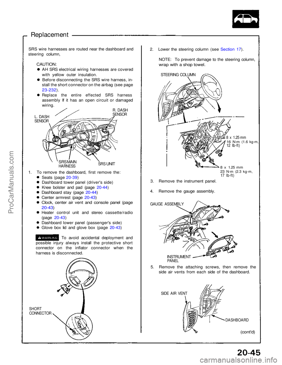
Replacement
SRS wire harnesses are routed near the dashboard and
steering column,
CAUTION:
AH SRS electrical wiring harnesses are covered
with yellow outer insulation.
Before disconnecting the SRS wire harness, in-
stall the short connector on the airbag (see page
23-232).
Replace the entire effected SRS harness
assembly If it has an open circuit or damaged
wiring.
R. DASH
SENSOR
L. DASH
SENSOR
SRS MAIN
HARNESS
SRS
UNIT
1. To remove the dashboard, first remove the: Seats (page 20-39)
Dashboard tower panel (driver's side)
Knee bolster and pad (page 20-44)
Dashboard stay (page 20-44)
Center armrest (page 20-43)
Clock, center air vent and console panel (page
20-43)
Heater control unit and stereo cassette/radio
(page 20-43)
Dashboard lower panel (passenger's side)
Glove box lid and glove box (page 20-43)
To avoid accidental deployment and
possible injury always install the protective short
connector on the inflator connector when the
harness is disconnected.
SHORT
CONNECTOR
(cont'd)
DASHBOARD
SIDE AIR VENT
5. Remove the attaching screws, then remove the
side air vents from each side of the dashboard.
INSTRUMENT
PANEL
GAUGE ASSEMBLY
3. Remove the instrument panel.
4. Remove the gauge assembly.
8 x
1.25
mm
23 N·m
(2.3 kg-m,
17 lb-ft)
8 x 1.25 mm
16 N·m
(1.6 kg-m,
12 Ib-ft)
STEERING COLUMN
2. Lower the steering column (see Section 17).
NOTE: To prevent damage to the steering column,
wrap with a shop towel.ProCarManuals.com