Page 1092 of 2103
AUTOMATIC TRANSAXLE
ENGINE (TURBO) AND On-vehicle Service
Lock nut
SERVO ADJUSTMENT
1. Completely remove all dirt and other materials adhered
around the
servo switch.
2. Remove the snap ring.
3. Remove the
servo switch.
4. To prevent rotation of the piston, engage the
of
the special tool into the notch of the piston, and using
the adapter, secure the piston as shown to the left .
Caution
1Don’t press in the piston with the special tool.
2.When mounting the adapter on the transaxle case,
tighten it by hand. Do not overtighten.
5. Loosen the lock nut to before the V-groove of the adjusting
rod, and tighten the special tool (inner) until it contacts
the lock nut.
TSB Revision
Page 1106 of 2103

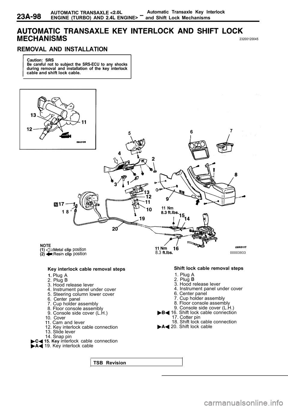
AUTOMATIC TRANSAXLE Automatic Transaxle Key Interlock
ENGINE (TURBO) AND ENGINE> and Shift Lock Mechanisms
23200120045
REMOVAL AND INSTALLATION
Caution:Be careful not to subject the SRS-ECU to any shocksduring removal and installation of the key interlockcable and shift lock cable.
567
I
- -
1 8 ’
NOTE(1) clip
(2) clipposition position
Key interlock cable removal steps
1. Plug A
2. Plug
3. Hood release lever
4. Instrument panel under cover
5. Steering column lower cover
6. Center panel7. Cup holder assembly
8. Floor console assembly9. Console side cover (L.H.)
10. Cover Cam and lever
12. Key interlock cable connection
13. Slide lever
14. Snap pin
15. Key interlock cable connection 19. Key interlock cable
11 Nm
8.30 0 0 0 3 9 3 3
Shift lock cable removal steps 1. Plug A
2. Plug
3. Hood release lever
4. Instrument panel under cover
6. Center panel
7. Cup holder assembly
8. Floor console assembly
9. Console side cover (L.H.)
16. Shift lock cable connection
17. Cotter pin
18. Shift lock cable connection
20. Shift lock cable
TSB Revision
Page 1107 of 2103
AUTOMATIC TRANSAXLE
ENGINE (TURBO) AND ENGINE> Lock
LOCK
I N S T A L L A T I O N
Secure the section between the metals of the
and key interlock cable with the of the steering cover
assembly.
Caution ,
Do not change the routing of shift lock cable to the
lever assembly. .
LOCK CABLE (SELECTOR LEVER SIDE)
INSTALLATION
(1) Place the selector fever in position
(2) Fasten the shift lock cable’ at the position where the end
of the shift lock cable is
above the red marking.
LEVER
I N S T A L L A T I O N
(1) Install the key interlock cable on the lock cam .
(2) Install the spring and washer of the key interl ock cable
as shown.
(3) While lightly pushing the cable coupling portio n of the
cam in-the direction A, tighten the nut to fasten the
key interlock cable. .
Check the cable assemblies for function and for dam
age.
TSB Revision
Page 1113 of 2103
AUTOMATIC TRANSAXLE . .
ENGINE (TURBO) AND ENGINE> Assembly
Front roll
stopper
bracket
ber
DRIVE PLATE
(1)Use a transmisslon jack to the ,,Caution
Support the transaxle
(2) Remove the connection bolts while turning
(3) Press the torque converter into the transaxle f or easier
removal.
(4) Remove the transaxle assembly mounting bolt and lower
the transaxle assembly.
,
SERVICE
TRANSAXLE ASSEMBLY
After securely inserting the torque converter the transaxle
so that the
shown in the becomes the refer-
ence value, install the assembly the engine.
value (A):
m m
12.0
ASSEMBLY
If the dimension shown in the is outside the standard
value when the weight of the engine the body, replace
the front roll stopper bracket assembly.
Standard value (A):
mm
D R I V E S H A F T
Temporarily install the drive shaft so that T.J. case of
the drive shaft is perpendicular to the
Caution
Do not damage the oil by part of the
drive shaft.
Transaxle
TSB Revision
Page 1116 of 2103

.AUTOMATIC TRANSAXLE
ENGINE (TURBO) AND ENGINE> Transaxle Assembly
,
Cord
N i t
TSB Revision
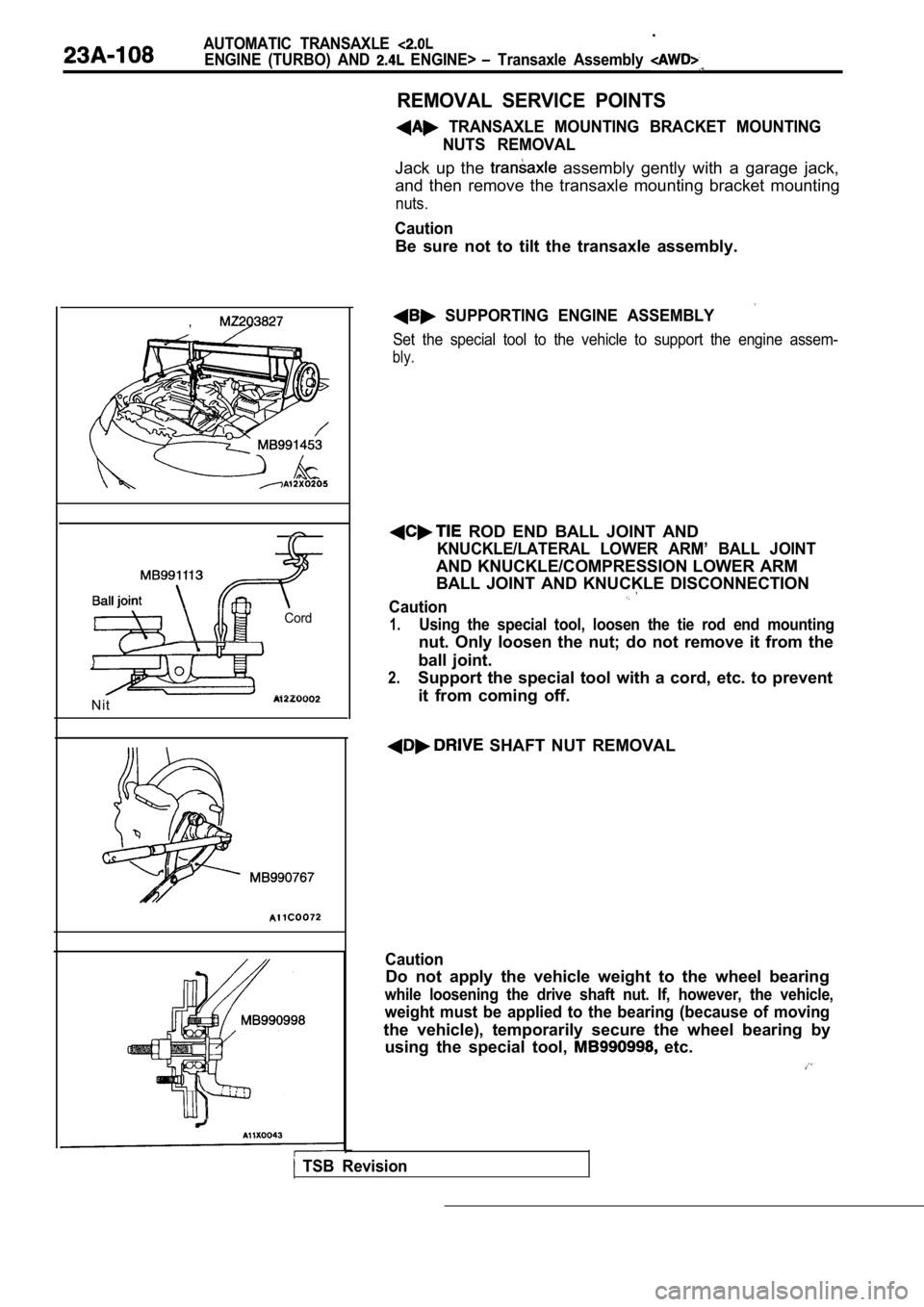
REMOVAL SERVICE POINTS
TRANSAXLE MOUNTING BRACKET MOUNTINGNUTS REMOVAL
Jack up the assembly gently with a garage jack,
and then remove the transaxle mounting bracket moun ting
nuts.
Caution
Be sure not to tilt the transaxle assembly.
SUPPORTING ENGINE ASSEMBLY
Set the special tool to the vehicle to support the engine assem-
bly.
ROD END BALL JOINT AND
KNUCKLE/LATERAL LOWER ARM’ BALL JOINT
AND KNUCKLE/COMPRESSION LOWER ARM
BALL JOINT AND KNUCKLE DISCONNECTION
Caution
1.Using the special tool, loosen the tie rod end moun ting
nut. Only loosen the nut; do not remove it from the
ball joint.
2.Support the special tool with a cord, etc. to preve nt
it from coming off.
SHAFT NUT REMOVAL
Caution
Do not apply the vehicle weight to the wheel bearin g
while loosening the drive shaft nut. If, however, the vehicle,
weight must be applied to the bearing (because of m oving
the vehicle), temporarily secure the wheel bearing by
using the special tool,
etc.
Page 1118 of 2103

AUTOMATIC TRANSAXLE
ENGINE (TURBO) AND ENGINE> Transaxle Assembly
Front roll
I - -
stopper
bracket
Centermember
Washer
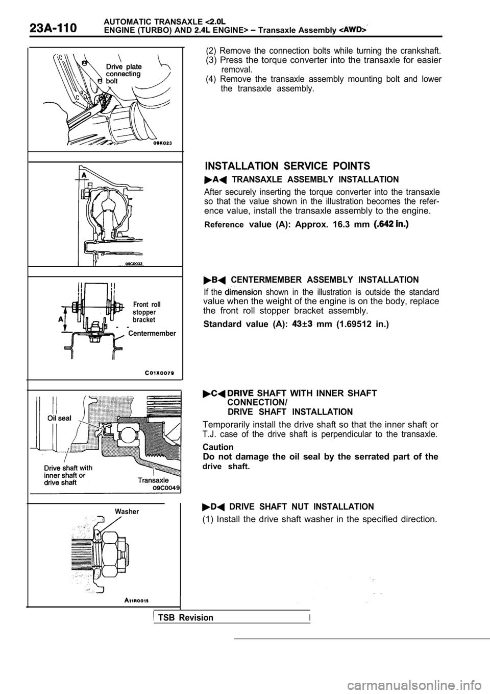
(2) Remove the connection bolts while turning the crankshaft.
(3) Press the torque converter into the transaxle for easier
removal.
(4) Remove the transaxle assembly mounting bolt and lower
the transaxle assembly.
INSTALLATION SERVICE POINTS
TRANSAXLE ASSEMBLY INSTALLATION
After securely inserting the torque converter into the transaxle
so that the value shown in the illustration becomes the refer-
ence value, install the transaxle assembly to the engine.
Reference value (A): Approx. 16.3 mm
CENTERMEMBER ASSEMBLY INSTALLATION
If the shown in the illustration is outside the standard
value when the weight of the engine is on the body, replace
the front roll stopper bracket assembly.
Standard value (A):
mm (1.69512 in.)
SHAFT WITH INNER SHAFT
CONNECTION/ DRIVE SHAFT INSTALLATION
Temporarily install the drive shaft so that the inn er shaft or
T.J. case of the drive shaft is perpendicular to th e transaxle.
Caution
Do not damage the oil seal by the serrated part of the
drive shaft.
DRIVE SHAFT NUT INSTALLATION
(1) Install the drive shaft washer in the specified direction.
TSB RevisionI
Page 1119 of 2103
A U T O M A T I C T R A N S A X L E
ENGINE (TURBO) AND ENGINE> Transaxle Assembly
(2) Use the special to
Caution
Before securely
sure there is no on the
(3) If the position of the cotter’ pin
tighten the nut up to 255
(4) Install the pin in bend
it securely.
TSB Revision
Page 1136 of 2103
AUTOMATIC TRANSAXLE ENGINE (NON -TURBO )> Troubleshooting
Code Diagnostic item
61Inadequate element volume: 2-4
62Inadequate element volume: OD
73Worn out/burnt transmission fluid
74Calculated oil temperature in use
Limp-in
No
No
No
No
R e f e r e n c e
Code Scan toolInternal control module Probable cause
No.11, 13,
General scan tool
TCM malfunction may be present. l
Malfunction of TCM
l Replace TCM
Code Scan tool 12
No.
Battery power was disconnected Probable cause
General scan tool since last power down
Battery disconnected or first installation.
l
Battery disconnected
A battery-backed RAM is used to maintain some learn ed values. When the battery isl(After securely connecting the battery, use the
disconnected, this memory is lost. When the battery is connected, this memory loss scan tool to erase the DTC.)
by the controller. The code is set and the learned values are initialized to known constants.
This results in the
of some parameters.
TSB Revision