1990 MITSUBISHI SPYDER ECU
[x] Cancel search: ECUPage 661 of 2103
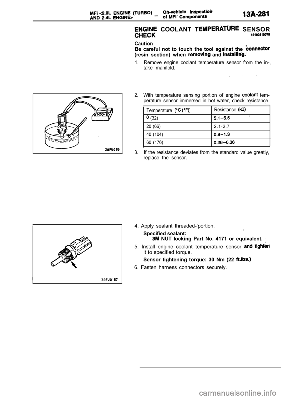
COOLANT SENSOR
Caution
Be careful not to touch the tool against the
(resin section) when and
1.Remove engine coolant temperature sensor from the in-,
take manifold.
2.With temperature sensing portion of engine tem-
perature sensor immersed in hot water, check resist ance.
,
Temperature
(32)
20 (66)
40 (104)
60 (176)
Resistance
2.1-2.7
3.If the resistance deviates from the standard value greatly,
replace the sensor.
4. Apply sealant threaded-‘portion. ,
Specified sealant:
NUT locking Part No. 4171 or equivalent,
5. Install engine coolant temperature sensor
it to specified torque.
Sensor tightening torque: 30 Nm (22
6. Fasten harness connectors securely.
Page 686 of 2103

FUEL SUPPLY Fuel Tank
FUEL GAUGE UNIT AND PUMP ASSEMBLY
REPLACEMENT
(1) Remove the rear seat cushion. (Refer to, GROUP
Seat.)
(2) Remove the protector.
(3) Disconnect the hoses and connectors to remove the fuel
pump assembly or fuel gauge unit.
(4) Align the packing positioning projections with. the
in the fuel pump assembly.
(1) Remove the rear seat cushion. (Refer to GROUP
Seat.)
(2) Remove the protector.
(3) Bleed the residual pressure inside fuel
to prevent the fuel from spraying’
(Refer to GROUP On-vehicle Service.)
(4) Disconnect the hose and connector ‘connections, ’ and
then remove the fuel
and pump assembly
(5)
or the fuel gauge unit and pipe
Check to be surethat the fuel tank packing damaged
or deformed, and then securely install the packing.
NOTE
If the packing is damaged or deformed? replace with new
packing.
(6) Apply soapy water to the inside of the packing, and “then
install the fuel gauge unit and pump assembly the
fuel gauge unit and pipe assembly..
.Caution
Do not tilt the fuel gauge unit pump
or the fuel gauge and pipe assembly when
installing.
TSB Revision
Page 759 of 2103
AND CONTROL
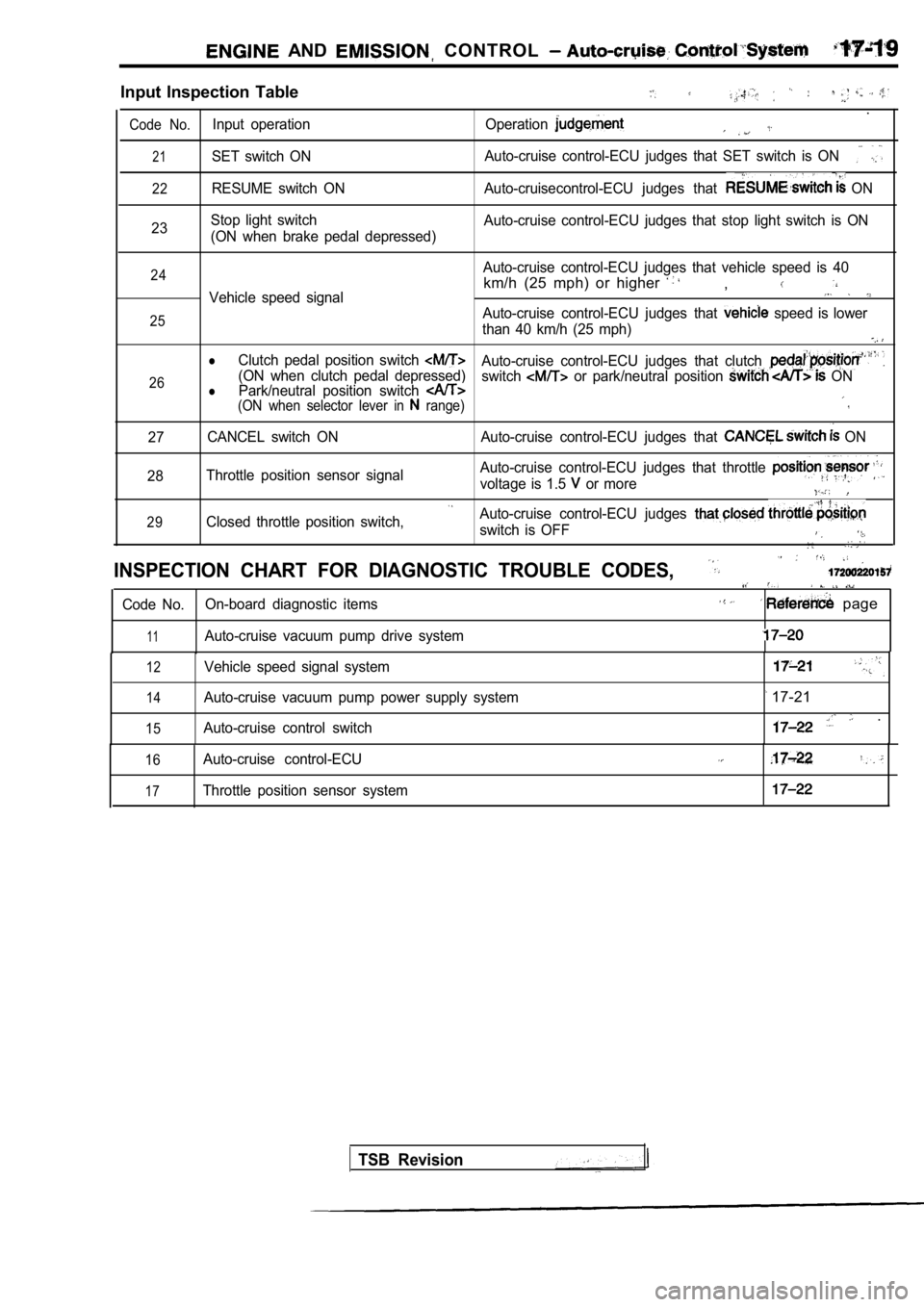
Input Inspection Table
.
Code No.Input operation Operation
21SET switch ONAuto-cruise control-ECU judges that SET switch is O
N
22RESUME switch ON Auto-cruisecontrol-ECU judges that ON
23 Stop light switch
(ON when brake pedal depressed) Auto-cruise control-ECU judges that stop light swit
ch is ON
24
25
26Auto-cruise control-ECU judges that vehicle speed i s 40
km/h (25 mph) or higher ,Vehicle speed signal
Auto-cruise control-ECU judges that speed is lower
than 40 km/h (25 mph)
lClutch pedal position switch Auto-cruise control-ECU judges that clutch (ON when clutch pedal depressed) Park/neutral position switch switch or park/neutral position ONl(ON when selector lever in range)
27 CANCEL switch ON Auto-cruise control-ECU judges that
ON
28 Throttle position sensor signal Auto-cruise control-ECU judges that throttle
voltage is 1.5 or more
29Closed throttle position switch,Auto-cruise control-ECU judges
switch is OFF
INSPECTION CHART FOR DIAGNOSTIC TROUBLE CODES,
Code No.
On-board diagnostic items page
11Auto-cruise vacuum pump drive system
12
14
15
Vehicle speed signal system
Auto-cruise vacuum pump power supply system
Auto-cruise control switch
17-21
.
16
17
Auto-cruise control-ECU
Throttle position sensor system
TSB Revision
Page 760 of 2103
![MITSUBISHI SPYDER 1990 Service Repair Manual E N G I N E A N D E M I S S I O N C O N T R O L Auto-cruise
INSPECTION PROCEDURE: FOR DIAGNOSTIC TROUBLE CODES
Code Auto-cruise vacuum pump drive system
[Comment]
This diagnostic MITSUBISHI SPYDER 1990 Service Repair Manual E N G I N E A N D E M I S S I O N C O N T R O L Auto-cruise
INSPECTION PROCEDURE: FOR DIAGNOSTIC TROUBLE CODES
Code Auto-cruise vacuum pump drive system
[Comment]
This diagnostic](/manual-img/19/57345/w960_57345-759.png)
E N G I N E A N D E M I S S I O N C O N T R O L Auto-cruise
INSPECTION PROCEDURE: FOR DIAGNOSTIC TROUBLE CODES
Code Auto-cruise vacuum pump drive system
[Comment]
This diagnostic trouble code is output if the release valve, control valve and motor drive signals
from the auto-cruise vacuum pump are not input to t he auto-cruise control-ECU.
(Refer to
l Malfunction of the auto-cruise vacuum pump
l Malfunction of the auto-cruise control-ECU
Measure at
control-ECU
connector
lDisconnect the connector and mea-sure at the harness side.
lVoltage between terminal (12) andground (for driving release valve)lVoltage between terminal (13) andground (for driving control valve)
lVoltage between terminal (26) andground (for driving motor)
OK: Battery positive voltage
Measure at auto-cruise vacuum pump
connector Stop light switch check
I
(Refer to l sure at the harness side.
l Voltage between terminal andgroundOK: Battery positive voltage
OK
auto-cruise control main switch and
auto-cruise vacuum pump. Repair, if
N G
and
OK
Check trouble symptom.
following
OK
Check trouble symptom.
NG
Replace the control-ECU.
TSB Revision
C h e c k t h e b e t w e e n t h eauto-cruisev a c u u m p u m p a n d
auto-cruise control-ECU. Repair, if
necessary.
Page 761 of 2103
![MITSUBISHI SPYDER 1990 Service Repair Manual ENGINE AND EMISSION CONTROL Auto-cruise Control’
Code 2 Vehicle speed signal system
[Comment]l Malfunction of the vehicle This diagnostic trouble code is output if the vehic le speed signa MITSUBISHI SPYDER 1990 Service Repair Manual ENGINE AND EMISSION CONTROL Auto-cruise Control’
Code 2 Vehicle speed signal system
[Comment]l Malfunction of the vehicle This diagnostic trouble code is output if the vehic le speed signa](/manual-img/19/57345/w960_57345-760.png)
ENGINE AND EMISSION CONTROL Auto-cruise Control’
Code 2 Vehicle speed signal system
[Comment]l Malfunction of the vehicle This diagnostic trouble code is output if the vehic le speed signals from the vehicle speed sensor l of connectorare not input to the auto-cruise control-ECU when t he vehicle speed is 40 km/h (25 mph) l
Malfunction of the harness
or more. l Malfunction of the auto-cruise
Check the vehicle speed sen(Refer to GROUP 54 CombinationMeter.)
1. NG
Measure at the vehicle speed sensor connector Check the following connector. l Disconnect the connector, and measure at the
harness side.O K
1. Voltage between 1 and ground (Ignition switch: ON)
NG
System voltage
2.Voltage between 3 and ground2. N G(Ignition switch: ON)
OK: 4.6 5.2 3.Continuity between 2 and ground3. N G
OK: Continuity
OK
Check trouble symptom.
N G
Check the harness between the speed sensor
Check the following
OKNG
Check trouble symptom.
NG
Check the harness between the auto-cruise ECU and the vehicle soeed sensor connector.
OKNG
Replace the auto-cruise control-ECU.
and ignition switch connector
OK
Check the ignition switch.
(Refer to GROUP 54 , ,
Check the harness between the vehicle speed sensorand the ground. Repair, if necessary.
Code Autocruise vacuum pump power supply systemProbable cause
[Comment]
This code will be output when the drive signals for the auto-cruise vacuum pump release valve,
control valve and motor are not input to the auto-c ruise control-ECU.l
the stop light l
Malfunction of the connector
l
l of the auto-cruise
at the auto-cruise vacuum
l Disconnect the connector and
l Voltage between terminal (1) and
OKN G Check the harness between the cruise vacuum pump and the cruise control-ECU.
and
Replace the auto-cruise control-ECU.
TSB Revision
Page 762 of 2103
17-22ENGINE AND EMISSION CONTROL Auto-cruise Control System
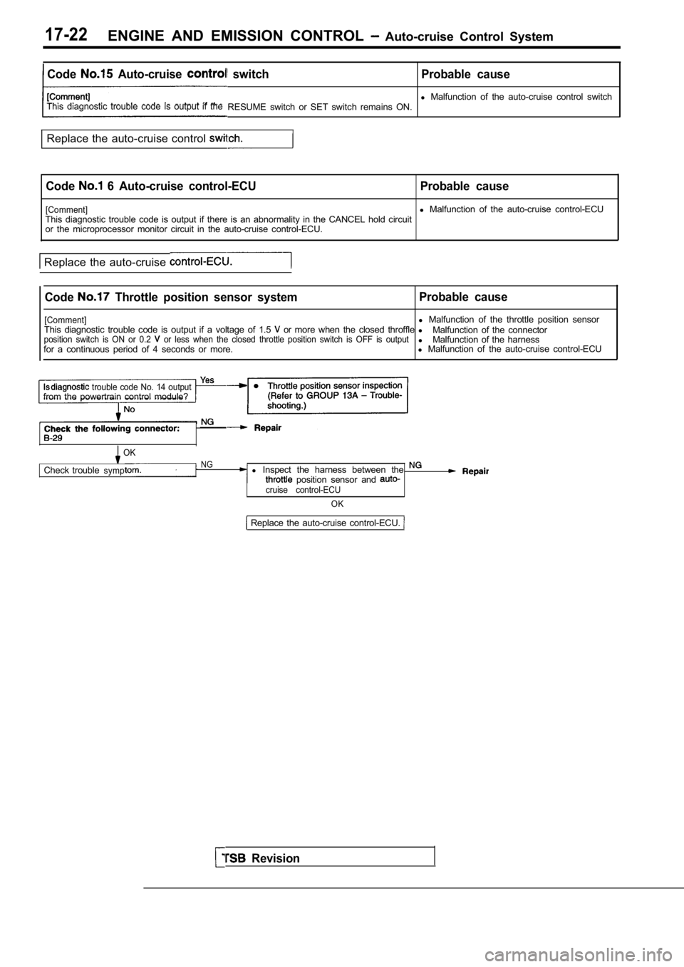
Code Auto-cruise switch Probable cause
l Malfunction of the auto-cruise control switch
This diagnostic trouble code is output if the RESUME switch or SET switch remains ON.
Replace the auto-cruise control
Code 6 Auto-cruise control-ECU Probable cause
[Comment]l Malfunction of the auto-cruise control-ECU
This diagnostic trouble code is output if there is an abnormality in the CANCEL hold circuit
or the microprocessor monitor circuit in the auto-c ruise control-ECU.
Replace the auto-cruise
Code Throttle position sensor system Probable cause
[Comment]l
Malfunction of the throttle position sensor
This diagnostic trouble code is output if a voltage of 1.5 or more when the closed throffle l
Malfunction of the connectorposition switch is ON or 0.2 or less when the closed throttle position switch i s OFF is outputlMalfunction of the harness
for a continuous period of 4 seconds or more. l
Malfunction of the auto-cruise control-ECU
trouble code No. 14 outputfrom the powertrain control module?
OK
Check troubleNGsympl Inspect the harness between the position sensor and cruise control-ECU
OK
Revision
Replace the auto-cruise control-ECU.
Page 763 of 2103
ENGINE AND EMISSION CONTROL Auto-cruise Control
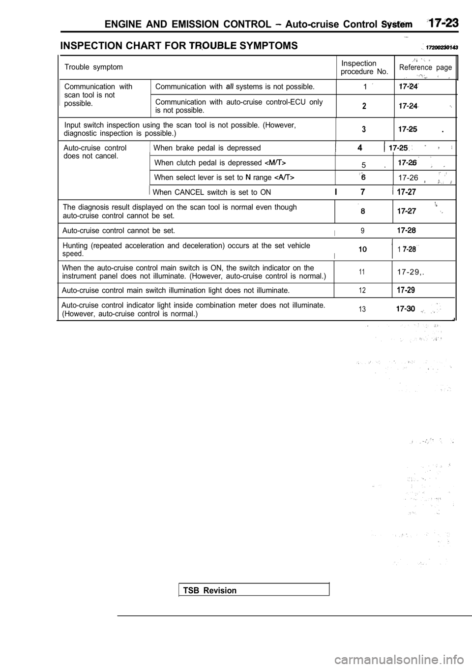
INSPECTION CHART FOR SYMPTOMS
Communication with
scan tool is not
possible. Communication with systems is not possible.
Communication with auto-cruise control-ECU only
is not possible.1
2
Input switch inspection using the scan tool is not possible. (However,
diagnostic inspection is possible.)3 .
Auto-cruise control When brake pedal is depressed 4 does not cancel. When clutch pedal is depressed
When select lever is set to range
When CANCEL switch is set to ON
5
17-26
I 7 17-27
Trouble symptomInspection
procedure No.Reference page
The diagnosis result displayed on the scan tool is normal even though
auto-cruise control cannot be set.
Auto-cruise control cannot be set.I9
Hunting (repeated acceleration and deceleration) oc curs at the set vehicle
speed.I1
When the auto-cruise control main switch is ON, the switch indicator on the
instrument panel does not illuminate. (However, aut o-cruise control is normal.)
Auto-cruise control main switch illumination light does not illuminate.111 7 - 2 9 , .
1217-29
Auto-cruise control indicator light inside combinat ion meter does not illuminate.
(However, auto-cruise control is normal.)13
TSB Revision
Page 764 of 2103
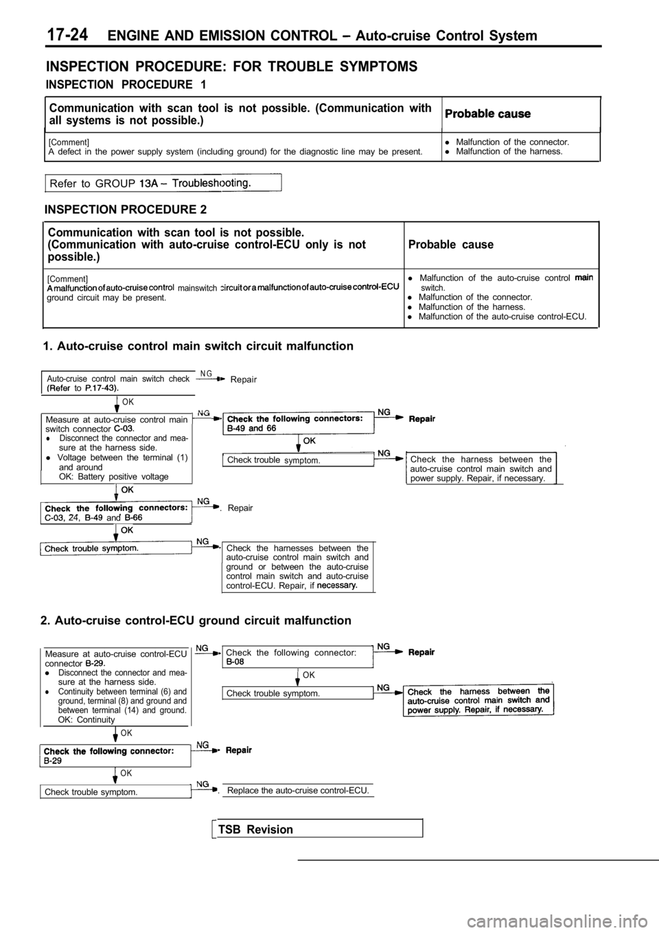
17-24ENGINE AND EMISSION CONTROL Auto-cruise Control System
INSPECTION PROCEDURE: FOR TROUBLE SYMPTOMS
INSPECTION PROCEDURE 1
Communication with scan tool is not possible. (Comm unication with
all systems is not possible.)
[Comment]A defect in the power supply system (including grou nd) for the diagnostic line may be present.
Refer to GROUP
INSPECTION PROCEDURE 2 l
Malfunction of the connector.
l Malfunction of the harness.
Communication with scan tool is not possible.
(Communication with auto-cruise control-ECU only is not
possible.) Probable cause
[Comment]l
Malfunction of the auto-cruise control mainswitch switch.ground circuit may be present. l
Malfunction of the connector.
l Malfunction of the harness.
l Malfunction of the auto-cruise control-ECU.
1. Auto-cruise control main switch circuit malfunct ion
Auto-cruise control main switch checkN G Repair to
OK
N G Measure at auto-cruise control main switch connector lDisconnect the connector and mea-sure at the harness side.
l Voltage between the terminal (1)
and around
OK: Battery positive voltage
Check troublesymptom.
. Repair 24, and
Check the harnesses between the auto-cruise control main switch and
ground or between the auto-cruise
control main switch and auto-cruise
control-ECU. Repair, if
2. Auto-cruise control-ECU ground circuit malfuncti on
Measure at auto-cruise control-ECU
connector
lDisconnect the connector and mea-sure at the harness side.lContinuity between terminal (6) and
ground, terminal (8) and ground and
between terminal (14) and ground.
OK: Continuity
OK
Check the harness between the
auto-cruise control main switch and power supply. Repair, if necessary.
Check the following connector:
OK
Check trouble symptom.
OK
Check trouble symptom. . Replace the auto-cruise control-ECU.
TSB Revision