Page 1154 of 2103

AUTOMATIC TRANSAXLE
ENGINE (NON-TURBO)> Troubleshooting
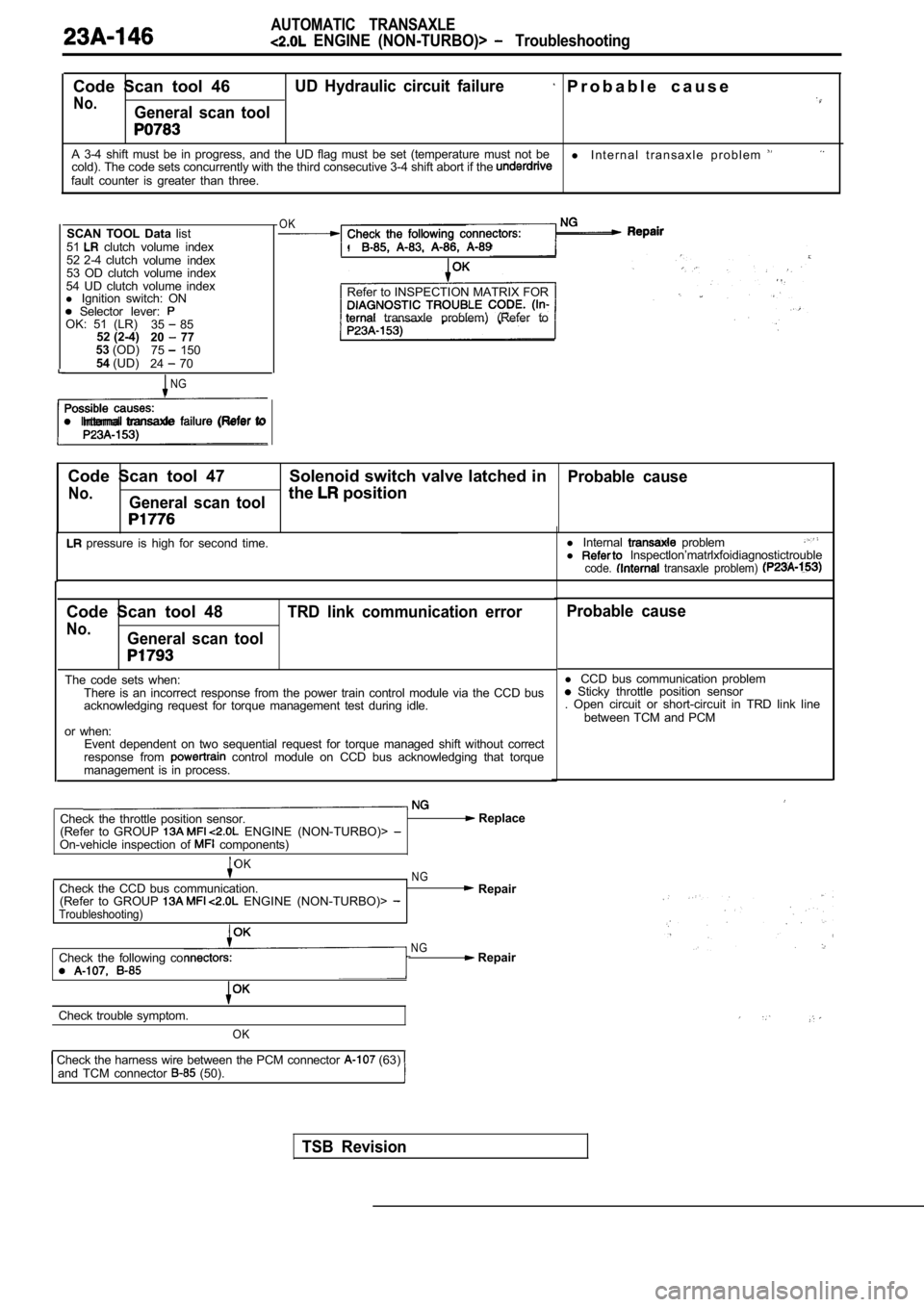
Code Scan tool 46UD Hydraulic circuit failure P r o b a b l e c a u s e
No.General scan tool
A 3-4 shift must be in progress, and the UD flag must be set (temperature must not be
l I n t e r n a l t r a n s a x l e p r o b l e m cold). The code sets concurrently with the third co nsecutive 3-4 shift abort if the fault counter is greater than three.
SCAN TOOL Data list
51
clutch volume index
52 2-4 clutch volume index
53 OD clutch volume index
54 UD clutch volume index
l Ignition switch: ON
Selector lever: OK: 51 (LR)
35 85
52 (2-4) 20 77
53 (OD)
75 150
54 (UD)
24 70
NG
l Internal transaxle (Refer to
OK
.
Refer to INSPECTION MATRIX FOR
transaxle problem) (Refer to
Code Scan tool 47 Solenoid switch valve latched in
Probable cause
No.General scan toolthe position
pressure is high for second time. l
Internal probleml lnspectlon’matrlxfoidiagnostictroublecode. transaxle problem)
Code Scan tool 48
No.General scan tool TRD link communication error
The code sets when:
There is an incorrect response from the power train control module via the CCD bus
acknowledging request for torque management test du ring idle.
or when: Event dependent on two sequential request for torqu e managed shift without correct
response from
control module on CCD bus acknowledging that torqu e
management is in process.
Check the throttle position sensor.
(Refer to GROUP ENGINE (NON-TURBO)> On-vehicle inspection of components)
Replace
OKNGCheck the CCD bus communication. Repair
(Refer to GROUP ENGINE (NON-TURBO)> Troubleshooting)
Check the following coNG Repair
Check trouble symptom.
OK
Check the harness wire between the PCM connector (63) and TCM connector (50).
Probable cause
l CCD bus communication problem Sticky throttle position sensor
. Open circuit or short-circuit in TRD link line
between TCM and PCM
TSB Revision
Page 1160 of 2103
AUTOMATIC TRANSAXLE
ENGINE (NON-TURBO)> Troubleshooting
Code Scan tool 74Calculated oil temperature in use Probable cause
No.General scan tool
This code will set when the Transaxle Thermistor Voltage is below volts or abovel Malfunction of oil temperature sensor
4.9412 volts for 15 seconds, for 3 consecutive engi ne starts.l or connector between transaxle rangesensor and TCM open or short-circuited
l Malfunction of TCM
Oil temperature sensor check. (Refer to
NG Replace
N G
Measure at the transaxle range sensor Check
connector A-l 08 .
l Disconnect the connector and
measure at the harness side.OK
NG Repair
1. Voltage between (4) and ground.
l . 2 value between (3) and
transaxle range sensor and the TCM
Replace the TCM
Check the following connector: .NG Repair
OK
Check trouble symptom.
NGCheck the harness wire between the Repair
transaxle range sensor and the TCM
TSB Revision
Page 1198 of 2103

AUTOMATIC TRANSAXLE
E N G I N E ( N O N - T U R B O ) >Automatic
Transaxle KeyInterlock and Shift LockMechanisms
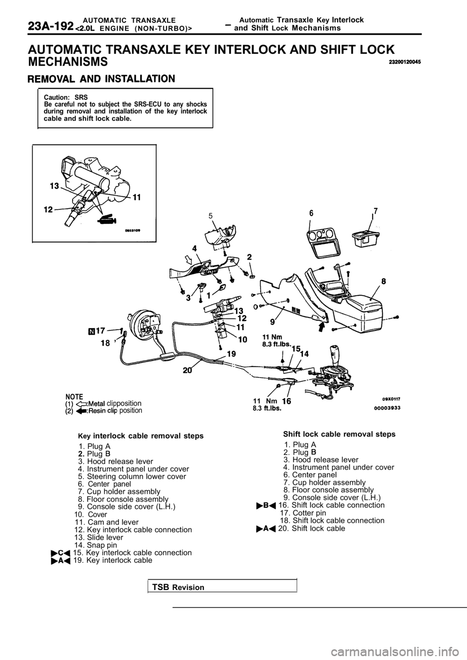
AUTOMATIC TRANSAXLE KEY INTERLOCK AND SHIFT LOCK
MECHANISMS
Caution: SRSBe careful not to subject the SRS-ECU to any shocksduring removal and installation of the key interloc kcable and shift lock cable.
NOTE
567I
8 ’
clipposition position
Key
interlock cable removal steps
1. Plug A
2. Plug
3. Hood release lever
4. Instrument panel under cover
5. Steering column lower cover
6. Center panel7. Cup holder assembly
8. Floor console assembly
9. Console side cover (L.H.)
10. Cover11. Cam and lever
12. Key interlock cable connection
13. Slide lever
14. Snap pin
15. Key interlock cable connection 19. Key interlock cable 11 Nm
8.3
Shift lock cable removal steps
1. Plug A
2. Plug
3. Hood release lever
4. Instrument panel under cover 6. Center panel
7. Cup holder assembly
8. Floor console assembly
9. Console side cover (L.H.)
16. Shift lock cable connection
17. Cotter pin
18. Shift lock cable connection
20. Shift lock cable
TSB Revision
Page 1199 of 2103
AUTOMATIC TRANSAXLE Key Interlock
E N G I N E a n d
SHIFT LOCK CABLE/
I N S T A L L A T I O N
Securethesection between the the
and key interlock cable the
assembly.
Caution
Do not change the of lock
lever assembly.’
L O C K C A B L E L EVER
INSTALLATION . .
(1) Place the
lever in
(2) Fasten the shift lock cable at the end
of the shift lock is-positioned the
KEY INTERLOCK CABLE (SELECTOR LEVER
(1) Install the key interlock cable cam.
(2) Install the spring and washer of
interlock cable
(3)
pushing the cable coupling portion of the
lock cam in the direction A, tighten the nut to fas ten the
key interlock cable.
INSPECTION
Check the cable assemblies for function and for dam age.
Page 1234 of 2103
AUTOMATIC TRANSAXLEOVERHAUL Transaxle
(3) Insert the transfer shaft in the case.
(4) Mount the special tool on the transaxle to
the transfer shaft.
(5) Install thethickest spacer in.)].
(8) Install the transfer driven gear on the shaft.
,
(7) Remove the tool and secure transfer shaft
in position.
TSB Revision
Page 1237 of 2103
OVERHAUL.
the
shaft plate.
and the lock plate should closed iri the
will prevent idler ‘shaft then tighten the
lock plate bolt to the
T i g h t e n i n g t o r q u e :
. , ,
, . .
t h e b e a r i n g
. . . .
the screw to specified torque.
Caution,
The screw not
Tightening torque;
.
. . . . , , __
the screw head in place using a chisel.
petrolatum jelly to thrust bearing and secure
the bearing on the planetary carrier.
the planetary carrier on the case.
TSB Revision
Page 1241 of 2103
A U T O M A T I C T R A N S A X L E
OVERHAUL Transaxle
the return spring.
--
petrolatum jelly the wave spring and attach the
wave spring to the center ,
the two new O-rings on the hydraulic pressure
holes of the center suppdrt.
Apply automatic transmission fluid to the O-rings;
the special tool to the center support. ‘Install the
center support slowly in
transaxle case, the
special tool.
Caution
1.During installation, take’ the wave
spring drop
was Step (30).
2. Install the two
the oil
holes
En. the
the special tool from the
the snap ring to secure the center support.
snap ring ends not interfere with the pulse genera-
tor mounting hole.
TSB Revision.I
Page 1250 of 2103
AUTOMATIC TRANSAXLE
OVERHAUL
I
the by, the following procedure:
(a) Fit the claw of the tool in the notch
piston to prevent, the piston from use
adapter to secure it as
left. . .
Caution
1. Do not push in the the
2.When the the
case, do apply but tight-
en by .
(b) Loosen the lock nut until it is reach the
V-groove in the adjusting special
tool (inner) until it the
(c) Fit the special (outer) to the lock the
outer cylinder counterclockwise and the inner cylin der
clockwise to lock lock nut and the special tool
(inner). ,. . ,
.
(d) Flit torque wrench to the to tighten
it to a torque of 10 Nm (7.2 and loosen. Repeat
this sequence two times before tightening the speci al
tool (inner) to 5 Nm (3.6
Then back off the special tool to
turns.
TSB Revision ,